Looking to expand the device capability I stumbled across a really interesting little project that is still in the early stages of development but, is functional and worth trying out.
The TC²-BBS Meshtastic Version is a simple BBS system that runs on a RaspberryPi, Linux PC or virtual machine (VM) and can connect to a Meshtastic device via either serial, USB or TCP/IP. Having my M0AWS-1 Meshtastic node at home connected to Wifi I decided to use a TCP/IP connection to the device from a Linux VM running the Python based TC²-BBS Meshtastic BBS.
Following the instructions on how to deploy the BBS is pretty straight forward and it was up and running in no time at all. With a little editing of the code I soon had the Python based BBS software M0AWS branded and connected to my Meshtastic node-1.
M0AWS Meshtastic BBS Main Menu accessible on M0AWS-1 node.
The BBS system is very reminiscent of the old packet BBS systems of a bygone era but, it is ideal for the Meshtastic world as the simple menus and user interface are easily transmitted in seconds via the Mesh using minimal bandwidth.
The BBS is accessible by opening a Direct Message session with the M0AWS-1 node. Sending the letter H to the node will get you the initial help screen showing the menu above and then from there onwards it’s just a matter of selecting the menu item and following the BBS prompts to use the BBS.
The BBS also works across MQTT. I tested it with Dave, G4PPN and it worked perfectly via the Meshtastic MQTT server.
This simple but, effective BBS for the Meshtastic network will add a new message store/forward capability to the Mesh and could prove to be very important to the development of the Meshtastic mesh in the UK and the rest of the world.
Following on from my article about my QO-100 Satellite Ground Station Complete Build, this article goes into some detail on the Node-RED section of the build and how I put together my QO-100 Satellite Ground Station Dashboard web app.
The Node-RED project has grown organically as I used the QO-100 satellite over time. Initially this started out as a simple project to synchronise the transmit and receive VFO’s so that the SDR receiver always tracked the IC-705 transmitter.
Over time I added more and more functionality until the QO-100 Ground Station Dashboard became the beast it is today.
M0AWS QO-100 Ground Station Control Dashboard built using Node-RED.
Looking at the dashboard web app it looks relatively simple in that it reflects a lot of the functionality that the two radio devices already have in their own rights however, bringing this together is actually more complicated than it first appears.
Starting at the beginning I use FLRig to connect to the IC-705. The connection can be via USB or LAN/Wifi, it makes no difference. Node-RED gains CAT control of the IC-705 via XMLRPC on port 12345 to FLRig.
To control the SDR receiver I use GQRX SDR software and connect to it using RIGCTL on GQRX port 7356 from Node-RED. These two methods of connectivity work well and enables full control of the two radios.
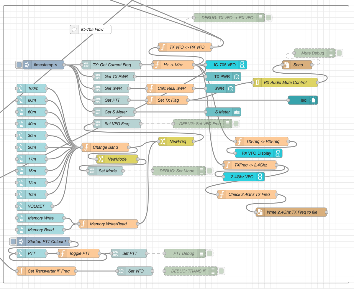
M0AWS Node-RED QO-100 Ground Station Dashboard Flow as of 12/06/24
The complete flow above looks rather daunting initially however, breaking it down into its constituent parts makes it much easier to understand.
There are two sections to the flow, the GQRX control which is the more complex of the two flows and the comparatively simple IC-705 section of the flow. These two flows could be broken down further into smaller flows and spread across multiple projects using inter-flow links however, I found it much easier from a debug point of view to have the entire flow in one Node-RED project.
Breaking down the flow further the GQRX startup section (shown below) establishes communication with the GQRX SDR software via TCP/IP and gets the initial mode and filter settings from the SDR software. This information is then used to populate the dashboard web app.
M0AWS Node-RED QO-100 Ground Station Dashboard – GQRX Startup Flow
The startup triggers fire just once at initial startup of Node-RED so it’s important that the SDR device is plugged into the PC at boot time.
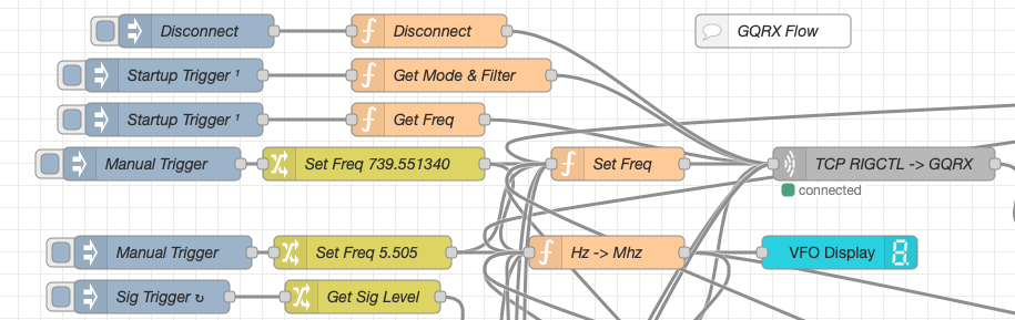
All the startup triggers feed information into the RIGCTL section of the GQRX flow. This section of the flow (shown below) passes all the commands onto the GQRX SDR software to control the SDR receiver.
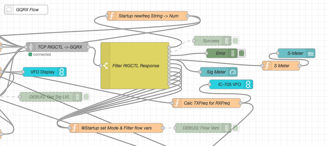
M0AWS Node-RED QO-100 Ground Station Dashboard – GQRX RIGCTL Flow
The TCP RIGCTL -> GQRX node is a standard TCP Request node that is configured to talk to the GQRX software on the defined IP Address and Port as configured in the GQRX setup. The output from this node then goes into the Filter RIGCTL Response node that processes the corresponding reply from GQRX for each message sent to it. Errors are trapped in the green Debug node and can be used for debugging.
The receive S Meter is also driven from the the output of the Filter RIGCTL Response node and passed onto the S Meter function for formatting before being passed through to the actual gauge on the dashboard.
Continuing down the left hand side of the flow we move into the section where all the GQRX controls are defined.
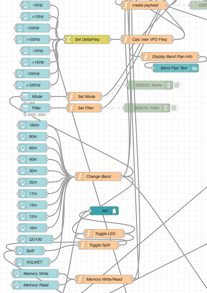
M0AWS Node-RED QO-100 Ground Station Dashboard – GQRX Controls Flow
In this section we have the VFO step buttons that move the VFO up/down in steps of 10Hz to 10Khz. Each button press generates a value that is passed onto the Set DeltaFreq change node and then on to the Calc new VFO Freq function. From here the new VFO frequency is stored and passed onto the communications channel to send the new VFO frequency to the GQRX software.
The Mode and Filter nodes are simple drop down menus with predefined values that are used to change the mode and receive filter width of the SDR receiver.
Below are the HAM band selector buttons, each of these will use a similar process as detailed above to change the VFO frequency to a preset value on each of the HAM HF Bands.
The QO-100 button puts the transmit and receive VFO’s into synchro-mode so that the receive VFO follows the transmit VFO. It also sets the correct frequency in the 739Mhz band for the downlink from the LNB in GQRX SDR software and sets the IC-705 to the correct frequency in the 2m VHF HAM band to drive the 2.4Ghz up-converter.
The Split button allows the receive VFO to be moved away from the transmit VFO for split operation when in QO-100 mode. This allows for the receive VFO to be moved away so that you can RIT into slightly off frequency stations or to work split when working DXpedition stations.
The bottom two Memory buttons allow you to store the current receive frequency into a memory for later recall.
At the top right of this section of the flow there is a Display Band Plan Info function, this displays the band plan information for the QO-100 satellite in a small display field on the Dashboard as you tune across the transponder. Currently it only displays information for the satellite, at some point in the future I will add the necessary code to display band plan information for the HF bands too.
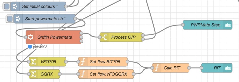
The final section of the GQRX flow (shown below) sets the initial button colours and starts the Powermate USB VFO knob flow. I’ve already written a detailed article on how this works here but, for completeness it is triggered a few seconds after startup (to allow the USB device to be found) and then starts the BASH script that is used to communicate with the USB device. The output of this is processed and passed back into the VFO control part of the flow so that the receive VFO can be manually altered when in split mode or in non-QO-100 mode.
M0AWS Node-RED QO-100 Ground Station Dashboard – Powermate VFO Flow
The bottom flows in the image above set some flow variables that are used throughout the flow and then calculates and sets the RIT value on the dashboard display.
The final section of the flow is the IC-705 control flow. This is a relatively simple flow that is used to both send and receive data to/from the IC-705, process it and pass it on to the other parts of the flow as required.
M0AWS Node-RED QO-100 Ground Station Dashboard – IC-705 Control Flow
The IC-705 flow is started via the timestamp trigger at the top left. This node is nothing more than a trigger that fires every 0.5 seconds so that the dashboard display is updated in near realtime. The flow is pretty self explanatory, in that it collects the current frequency, transmit power, SWR reading, PTT on/off status and S Meter reading each time it is triggered. This information is then processed and used to keep the dashboard display up to date and to provide VFO tracking information to the GQRX receive flow.
On the left are the buttons to change band on the IC-705 along with a button to tune to the VOLEMT on the 60m band. Once again there two memory buttons to save and recall the IC-705 VFO frequency.
The Startup PTT Colour trigger node sets the PTT button to green on startup. The PTT button changes to red during transmit and is controlled via the Toggle PTT function.
At the very bottom of the flow is the set transverter IF Freq function, this sets the IC-705 to a preselected frequency in the 2m HAM band when the dashboard is switched into QO-100 mode by pressing the QO-100 button.
On the right of the flow there is a standard file write node that writes the 2.4Ghz QO-100 uplink frequency each time it changes into a file that is used by my own logging software to add the uplink frequency into my log entries automatically. (Yes I wrote my own logging software!)
The RX Audio Mute Control filter node is used to reduce the receive volume during transmit when in QO-100 full duplex mode otherwise, the operator can get tongue tied hearing their own voice 250ms after they’ve spoken coming back from the satellite. This uses the pulse audio system found on the Linux platform. The audio is reduced to a level whereby it makes it much easier to talk but, you can still hear enough of your audio to ensure that you have a good, clean signal on the satellite.
As I said at the beginning of this article, this flow has grown organically over the last 12 months and has been a fun project to put together. I’ve had many people ask me how I have created the dashboard and whether they could do the same for their ground station. The simple answer is yes, you can use this flow with any kind of radio as long as it has the ability to be controlled via CAT/USB or TCP/IP using XMLRPC or RIGCTL.
To this end I include below an export of the complete flow that can be imported into your own Node-RED flow editor. You may need to make changes to it for it to work with your radio/SDR but, it shouldn’t take too much to complete. If like me you are using an IC-705 and any kind of SDR controlled by GQRX SDR software then it’s ready to go without any changes at all.
A couple of years ago I built a Matrix Synapse server and connected it to the decentralised global Matrix chat network that is federated world wide by enthusiasts who host their own Matrix servers. Due to the enthusiasm for a decentralised network the Matrix has grown exponentially and is now an established force in the world of Opensource global communication services.
When I built my server and configured it online my aim was to bring together an enthusiastic group of Radio Amateurs (Radio HAMs) who could build a friendly, welcoming community where people could share, learn and have fun with other liked minded individuals without all the nonsense you see on commercial social media platforms.
Overtime we’ve increased the number of rooms available in the HAM Radio space and the number of subjects covered. This has grown organically as our community has grown and we’ve ventured together into new areas of the hobby.
Global Matrix Ham Radio Space hosted on the M0AWS Matrix Server
From the community a number of projects have spawned including the Opensource.radio Wiki that Mike, DK1MI is sponsoring that aims to detail all the Opensource HAM Radio software, Hardware and projects in one centralised site on the internet. This is a great project and one I am very happy to contribute to.
Thanks to Mike, DK1MI we now also have our own Matrix AllStarLink node available. This is a great resource for the community as it is often not possible for all of us to communicate via the radio waves due to geo-location, time zones, local planning regulations etc. Having this 24/7 internet based resource makes it a lot easier for the community to chat at any time even when propagation on the HF bands isn’t in our favour.
We also have a very active satellite room with regular nets on the QO-100 satellite. With such a great range of rooms and subjects there’s plenty to read and talk about with the community.
If you fancy being part of this growing, enthusiastic group of Radio Amateurs and Short Wave Listeners (SWLs) then click on the link below and come and say hello, a warm welcome awaits!
I get quite a few emails from readers of my blog asking how my QO-100 satellite station is put together and so, I thought perhaps now is a good time to put together an article detailing the complete build.
My QO-100 satellite ground station is built around my little Icom IC-705 QRP transceiver, it’s a great little rig and is ideal for the purpose of driving a 2.4Ghz transverter/up-converter.
Of course all the software used for the project is Opensource and freely available on the internet.
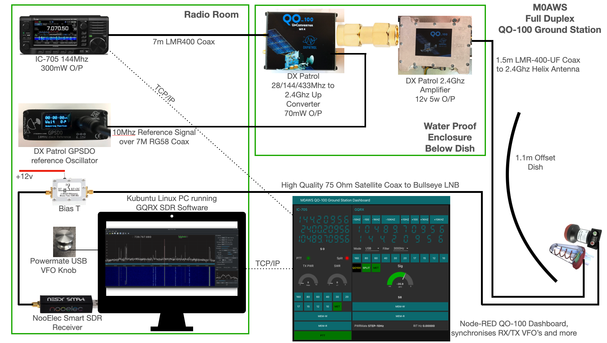
M0AWS QO-100 Ground Station Build Visual (Click to Enlarge)
The station comprises of the following building blocks:
QO-100 Ground Station Dashboard developed using Node-RED
LMR400-UF/RG58 Coax Cable
M0AWS QO-100 1.1m (110cm) off-set Dish with IceCone Helix antenna and Bullseye LNB.
To get a good clear view of the QO-100 satellite I have the dish mount 3.2m above the ground. This keeps it well clear of anyone walking past in the garden and beams the signal up at an angle of 26.2 degrees keeping well clear of neighbouring gardens.
The waterproof enclosure below the dish houses all the 2.4Ghz equipment so that the distance between the feed point and the amplifier are kept to a minimum.
The DXPatrol amplifier is spec’d to run at 28v/12w or 12v/5w, I found that running it at 28v produced too much output for the satellite and would cause the LEILA alarm on the satellite to trip constantly. Running the amp at 12v with a maximum of 5w output (average 2.5-3.5w) is more than enough for me to have a 5/9+10 signal on the transponder.
The large 1.1m dish gives me quite an advantage on receive enabling me to hear the very weak stations with ease compared to other stations.
2.4Ghz ground station enclosure ready for testing
The photo above shows the 2.4Ghz equipment mounted in the waterproof enclosure below the dish. This photo was taken during the initial build phase before I rewired it so, the amplifier is shown connected to the 28v feed. To rewire the amp to 12v was just a matter of removing the 28v converter and connecting the amp directly to the 12v feed instead. This reduced the output from a maximum of 12w down to a maximum of 5w giving a much better (considerate) level on the satellite.
It’s important to keep all interconnects as short as possible as at 2.4Ghz it is very easy to build up a lot of loss between devices.
For the connection from the IC-705 to the 2.4Ghz Up-Converter I used a 7m run of LMR-400 coax cable. The IC-705 is set to put out just 300mW on 144Mhz up to the 2.4Ghz converter and so it’s important to use a good quality coax cable.
Once again the output from the 2.4Ghz amplifier uses 1.5m of LMR-400-UF coax cable to feed up to the 2.2 turn Icecone Helix Antenna mounted on the dish. This keeps loss to a minimum and is well worth the investment.
Bullseye 10Khz High Stability Unversal Single LNB for 10.489-12.750Ghz
The receive path starts with a Bullseye LNB, this is a high gain LNB that is probably one of the best you could use for QO-100 operations. It’s fairly stable frequency wise but, does drift a little in the summer months with the high temperature changes but, overall it really is a very good LNB.
The 12v feed to the LNB is via the coax and is injected by the Bias-T device that is in the radio shack. This 12v feed powers the LNA and associated electronics in the LNB to provide a gain of 50-60dB.
Bias-T to inject 12v feed into the coax for the Bullseye LNB
From the Bias-T the coax comes down to the NooElec SmartSDR receiver. This is a really cheap SDR device (<£35 on Amazon) based on the RTL-SDR device but, it works incredibly well. I originally used a Funcube Dongle Pro+ for the receive side however, it really didn’t handle large signals very well and there was a lot of signal ghosting so, I swapped it out for the NooElec SDR and haven’t looked back since.
The NooElec SmartSDR is controlled via the excellent Opensource software GQRX SDR. I’ve been using GQRX SDR for some years now and it’s proven itself to be extremely stable and reliable with support for a good number of SDR devices.
To enhance the operation of the SDR device I have added a Griffin Powermate VFO knob to the build. This is an old USB device that I originally purchased to control my Flex3000 transceiver but, since I sold that many moons ago I decided to use it as a VFO knob in my QO-100 ground station. Details on how I got it working with the station are detailed in this blog article.
Having the need for full duplex operation on the satellite this complicates things when it comes to VFO tracking and general control of the two radios involved in the solution and so I set about creating a QO-100 Dashboard using the great Node-RED graphical programming environment to create a web app that simplifies the management of the entire setup.
M0AWS QO-100 ground Station Control Dashboard built using Node-RED.
The QO-100 Dashboard synchronises the transmit and receive VFO’s, enables split operation so that you can transmit and receive on different frequencies at the same time and a whole host of other things using very little code. Most of the functionality is created using standard Node-RED nodes. More info on Node-RED can be found on the Opensource.radio Wiki or from the menu’s above.
I’ll be publishing an article all about the QO-100 Dashboard in the very near future along with a downloadable flow file.
I’m extremely pleased with how well the ground station works and have had well in excess of 500 QSO’s on the QO-100 satellite over the last last year.
With the recent explosion of artificial intelligence (AI) art generators that are making the news of late for all the wrong reasons, I decided to see if I could put it to good use and design some futuristic QSL cards.
Having recently been contacted by the Special Callsigns QSL Manager and being advised that there were 18 QSL cards waiting for me, I decided it was time to create some QSL cards of my own for future use.
Having never used any form of online AI and not having any artistic abilities I was amazed how easy it was to create images using nothing more than a paragraph or so of text to describe what it was I wanted to create.
Since all the QSL cards I received were for contacts on the QO-100 satellite, I set out to create a visually futuristic QSL card that was based around a radio HAM operator and satellite communications.
M0AWS – 1st attempt at creating a futuristic QSL card image using AI Art
To my surprise the results of my first image generation were surprisingly good. The AI generated an image that resembled the simple text that I entered, although I never requested a one legged HAM operator!
Pleased with my very first attempt I gradually improved the description of what I was looking for, adding more and more detail to the text and including things that I wanted to see in the image. Over a fairly short period of time this approach started to generate some very interesting images.
M0AWS – AI Art QSL Image attempt 2M0AWS – AI Art QSL Image attempt 3M0AWS – AI Art QSL Image attempt 4
With each iteration I gradually got closer to what I was trying to achieve but, never quite got exactly what I wanted so, I decided to rewrite the descriptive text adding even more information than before. The text was now a full blown paragraph with quite specific things described including the angle at which the scene was being viewed from.
The other option I wanted to try out was the theme functionality that the AI offered. This allows you to set a theme for the image from things like steampunk, cartoon, manga, real world and many more. The results were quite impressive and added yet another angle to the image generation.
M0AWS – AI Art QSL Theme 1M0AWS – AI Art QSL Theme 3M0AWS – AI Art QSL Theme 2
I disappeared down the theme AI Art generation rabbit hole for quite some time and generated some very interesting and fun results. The best by far though was the Thunderbirds themed image, this did put a smile on my face!
M0AWS – AI Art QSL Thunderbirds Themed
At the other end of the spectrum I tried the Salvador Dalli theme, it produced an image that was very like the work of the famous artist but, wasn’t quite what I was looking for.
M0AWS – AI Art QSL Salvador Dalli Themed
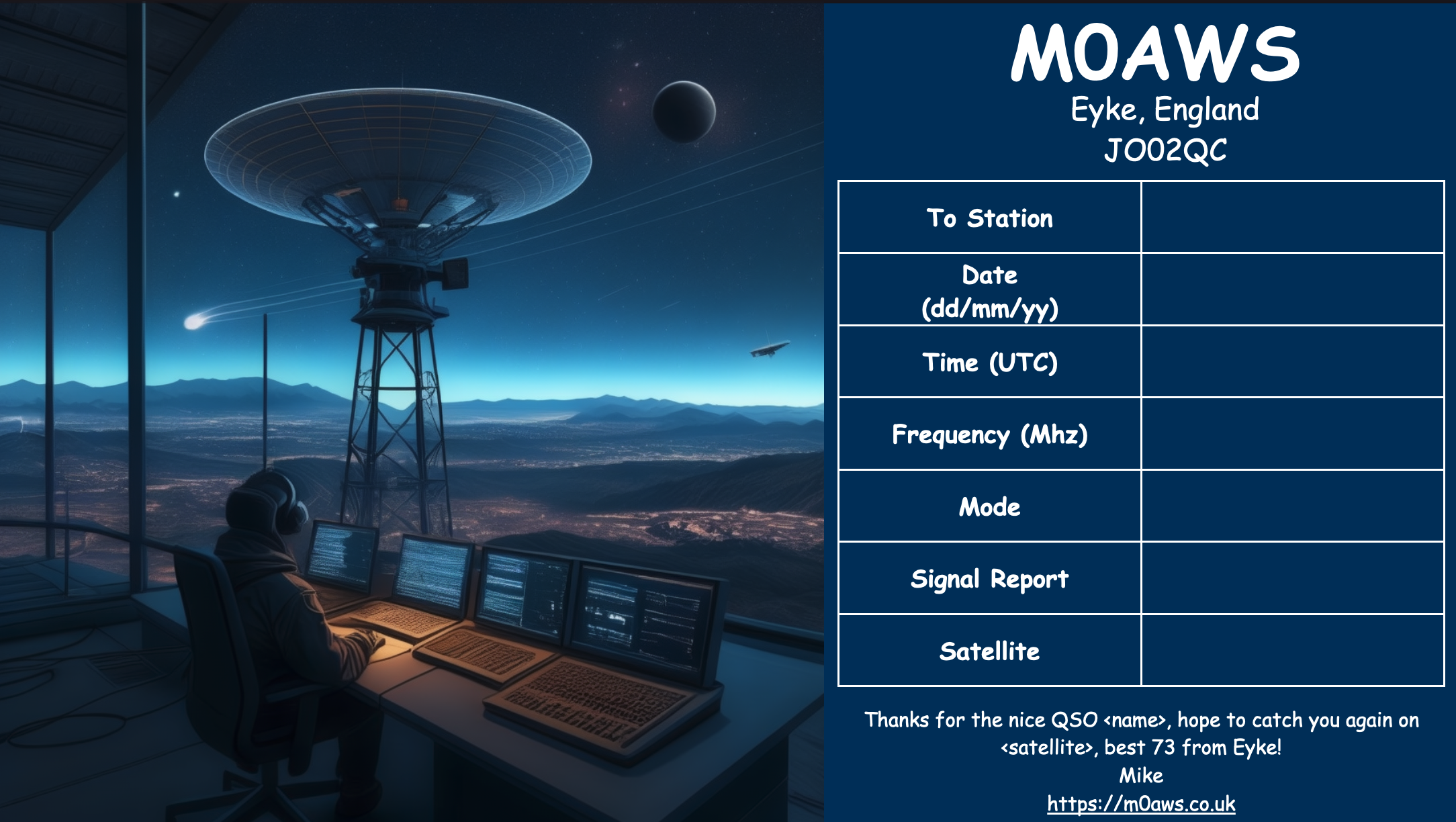
After much fun I eventually settled on the image I was after, a futuristic scene of a radio HAM with a satellite ground station over looking a mountain range and city below.
M0AWS Satellite QSL Card generated using online AI
I’m really pleased with the results from my ventures into AI generated art. The next challenge is to create a QSL card for HF bands Contacts.
ok i got fired up and started typing and wrote a bunch so sorry, but #offmychest… I wasn’t a big fan of the 1984ing on the stream bc i wanna hear out and debate the hot takes. During the stream I was typing that whole time with @QROdaddy (W4IPC) because he got quieted and I wanted to hear the discord (haha pun). I really don’t like echo chambers, and I really don’t like stuff that doesn’t take holistic perspectives from all points of view, so I think we, the radiosport2.0 community need to take some better care hearing it out. Whether it’s from current youth, young and old, seasoned or noob contesters, non-contesters, or QRZ lol. With that being said, here’s my dissertation on the whole radiosport thing that’s been bouncing in my head since 2011 (https://www.arrl.org/news/youth-hamradio-fun-what-is-radiosport-and-why-do-we-do-it) and opined since 2016 (https://n0ssc.com/posts/320-contest-modernization also rip cqcontest.net but today’s is https://contestonlinescore.com) I think we want the same thing – we contesters all want to contest, and for there to be people to contest with well into the future. I think the ideas we’re tossing around formulates an inviting, fertile ground for new contesters just coming into ham radio and contesting for the first time. Out of this, I hope we discover and create novel in-roads for normies to get into the next level. Current young contesters may think it’s great right now, because it is, but you are a lucky few who had some kind of magical unmatched personal dedication, brilliant elmering, ham family, or just ADHD hyperfocus (it me) to get hooked for life. And i’m v proud of that. But without pushing for some kind of modern, mainstream aligned ideas, environments, activities, overlays, categories, and just straight up new stuff, radiosport will stagnate as the VAST BULK of contesters pass away, out leaving behind a fraction of today’s young contesters for tomorrow. That’s facts based on statistical projections based on numerous demographic surveys and data, and you can see it plainly in Craig’s K9CT interview. So as content creators, visionaries, and rabblerousers, we’re gonna go in hot and heavy, get complainy, and poke at the hornet’s nest to bring this to the light throughout the ham community to find people interested in making it a thing, only to see if it’s a thing. Might want to work on the delivery, but the point stands.
I also think we are miscommunicating the intent of radiosport2.0 becasuse of all the “reeeeee your killing my contests get off my lawnnnn nothing is wrong why do this nooo reeee” type comments . and I don’t disagree there might be some misinformation, or really just ignorance and misremembering on our (my lol) part. There’s also the weirdness of the K9CT folks, ARRL/CAC people, and log developers keeping their radio sport 2.0 plans close to their chest (compared to us who are baring it all and at least showing somebody is out there thinking “it would be cool if…”in hopes we can garner some grassroots perturbations in the community and do something cool for the sake of the fun of it, and maybe for the sake of the hobby). But imagine things like saving the contest committee 100 hours out of their thousands to check logs by, i dunno, posting every log submission and qsordr capture carte blanche to an academic database and letting the database wizards poke at it to see how close their solutions come to the traditional methods? Or giving those connected to the internet an opt-in option to cryptographically sign their QSOs that get posted to a blockchain ledger as a smart contract for realtime, verifiable adjudication (and figure it’s vulnerabilities to nefarious players? Or let there be a new button in their log’s score reporting menu that says “send to realtime ledger” or “report [entire QSO/band-mode/freq/rotator] data to blahblahblah db/server” for beta testers and early adopters to futz with while also not ruining or even remotely changing their experience as a contester doing a contest – they’ll still be valid (depending on what they’re opting in to send they might need to change to a different category e.g. CQWW Explorer), they’ll still submit a cabrillo, they’ll get a real score in whenever time, meanwhile 99% of people probably won’t notice that button until HRCC hosts a livestream of a radiosport tournament battle royale with your hosts Kyle AA0Z and Sterling N0SSC, backed up by your experts in the field N0AX and N6MJ – all enabled by that button, only just now realizing they too can get in on that action ALL THE WHILE on the air it just sounds like regular contesters contesting; just with more of them doing this goofy livestreamed tournament thing.
And I’m not a “*real*” contester. I don’t put up high scores on 3830 because I cannot do a 24/36/48 hr contest. I go to N0AX/W0ECC/W0EEE, sit down for 2 hours, do my 200-300Q/hr rate, let the pile die, and give up for a while with a beer and a chat with the other’s on the bench, and come back at 4am when the grey line is approaching to listen to the world turn from 160m and 10m because that shit is cool. I don’t even have HF at home, and I don’t have the time to set up remote stations and be a basement dweller for a whole weekend. And I have gone a loooong time since I had my butt in a chair for more than a few hours that wasn’t at my day job. But I’ve worked at least 2 or 3 big contests every year since I was 15 years old, I’ve won plaques and paper as a sad teenage G5RV owner in nowhere Missouri, i’ve played in sweeps every year except one (not under my own callsign typically – usually under N0AX, W0ECC, and W0EEE), I drop in at random field day sites and fire through 100 QSOs in half an hour and disappear, and I had elmers like N0AX, Ed K0KL (SK), K0ZT (SK) K0ZH and the WA0FYA Zerobeaters ARC, W0EEE alumni, and K3LR and the Contest University crew who let me in free for like 3 years straight because I was the only one without gray hair. I really love contesting – it’s my favorite part of ham radio. And now as a 32 year old geezer, I do want something I can do in my tidbits of free time, that is just a bit different than a CWT or WWSAC, that isn’t just a 2 hour stint on a major contest – i want to be competitive and be ranked and scored with a pool of other contesters. I want team deathmatch, CTF, in-game perks/power-ups/items, and matchmaking lobbies. I think there’s an untapped reserve of potential new hams that would also be into that kind of radiosport. I don’t want the existing contests or methodologies to die or change, but as they stand now – as they have forever ago and forever on — are excellent grounds for trying out these new ideas unbeknownst to guys like VP5M with barely enough bandwidth for the cluster [thanks connor], the off-grid pacific islanders, africans, antarctic researchers, nordic polar bears all who make CQWW/WPX & IARUHF so much fun, or folks who just don’t do the internet and log with paper. Coexistance is a requirement, and so is the longevity of our hobby.
Tldr I want to play ham radio when I’m retired (25-30 years from now lol) so I have some ideas.
***
a few edits were made for profanity, clarification, correction to K0ZH’s call.
thanks W4IPC and KG5XR for inspo and AA0Z for sticking his neck out to get these ideas on the cutting room floor
It’s been a busy few months, and the folx who I interact with on Mastodon already know that I’ve got lots of irons in lots of fires. I figured it’s probably time for me to do a quick ‘state of the shack’ post to give a quick highlight on where all my various projects and activities stand, in case anyone has been wondering about the status of any particular item.
The quick summary here, is that my Motorola GR1225 died, so I currently have a machine on the air using a pair of Kenwood TK840 radios, the duplexer from the Motorola, and a new USB interface from Repeater-Builder to connect it to the computer that runs the Allstar software. After some very positive feedback on the post I wrote as I was trying to get the machine running again, I decided to start a fund-raiser to support some upgrades to the repeater, and to also help repair and get some additional repeaters on the air, which brings us to the next project…
r4e is an acronym for Repeaters 4 Everybody.
As a way to support upgrades on my repeater and some additional repeaters that are operated with a purposeful mission of openness and acceptance, and to help bulk up the RF side of the Pride Radio Network, I’ve started the r4e project which some of you may have stumbled across already in the header of my site. If you’re willing to help support some repeaters financially, or with donations of equipment, or to just connect an existing repeater to the pride network, those gifts and actions can go a long way towards our roadmap!
This project is an offshoot of the r4e project, and is a way to raise additional funds for those projects by selling radio merch that (I hope) is unlike most of the stuff already out there. Buy some cool stuff to support the project!
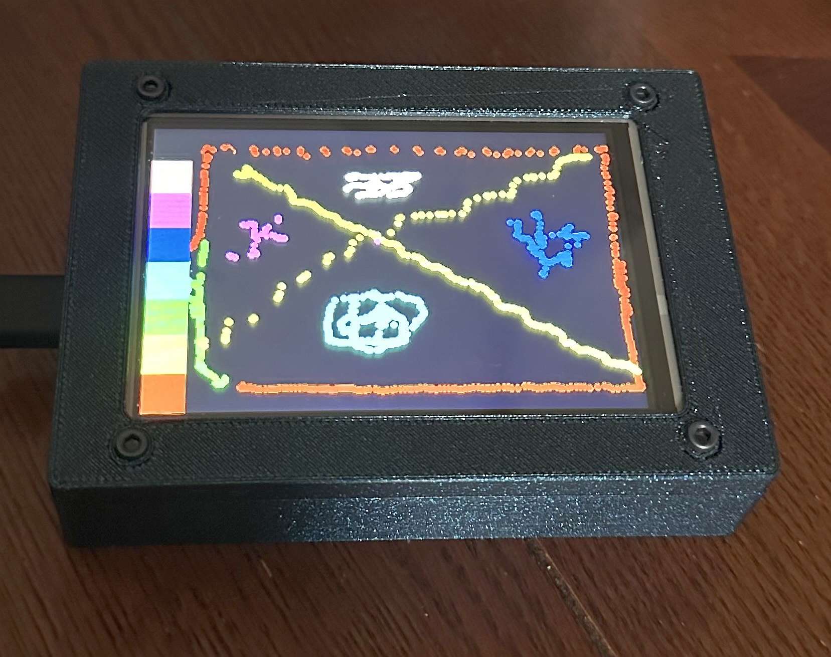
Version 3 of the rocket (Ponzu) had some body tube damage during its first flight, which is now repaired, and it’s ready to fly again. I also built a new ground station that is an all-in one unit with the single board computer, LoRa receiver, an RTL-SDR dongle for receiving APRS packets, touchscreen for launch control and data display, etc. Motors are ordered for the next launch, which will be on June 13th or 14th, as weather permits.
A while back I joined the Narwhal Amateur Radio Society (NR7WL) - they’re a relatively new club, but have values that I dig. We had kicked around the idea of a club ‘network’ to be able to connect via digital modes, and potentially a club net. That idea sat for a little bit, but bubbled back up recently, so I took the initiative to set up an Allstar node for the club (61672) which will serve as our hub, and the location for our first club net, for which I’ll be serving as net control!
Net details as follows:
Narwhal Amateur Radio Society Club Net
Time: 1st Tuesday of Every Month at 7pm Pacific, 10pm Eastern
Location: Hosted on the NR7WL Allstar Node (61672) and the Pride Radio Network. The Pride Radio network has bridges that will allow you to connect via DMR, IRLP, System Fusion, M-17, NXDN, P-25, D-Star, Echolink, Hamps Over IP, Hamshack Hotline, plus others!
I haven’t made any major updates to the shack recently, but I have moved a few things around. In the utility space behind the operating position I added a DIY rack made from lumber to move the various computer and network bits and bobs into. My next project in the shack is related to re-doing some of the audio routing - I have designs drawn up in KiCad for an interface device that will sit beside my mixer and convert all the audio to the OHIS standard. The basic reasoning behind this for me, is that by converting the audio to OHIS, I can leverage an existing standard to run a single shielded cat6 cable to each radio and device, instead of the 3 or 4 audio and PTT cables that run to each radio now. I currently have some bursting-at the seams cable management, and doing this should reduce the mess in there quite a bit. The plan is also to eventually replace my aging mixer, and build a new rack mount arrangement to the left of my operating position to house the mixer, interface, and some other related shack equipment.
Diversity is something important to our hobby. If you disagree, or think this statement is somehow political, you’re part of the problem in the hobby, and I won’t engage with you on the subject. If you do feel the same way I do however, the ARIP is one of my projects that is essentially a tool that clubs, individuals, or other organizations can use as a way to show their commitment to inclusion in the hobby. The most recent update on this effort is some changes to the website and methodology to make it more of a self-serve tool. There is more information about that available on the ARIP Website
Currently, the Radio League of America (RLA) is little more than an idea. That idea being that the amateur radio community is too large and diverse for everyone to have their voices heard by a single national organization. There are many amateurs who have voiced a desire for something different to be available, and the RLA is just one of many potential avenues as that movement takes life. I have committed to at some point in the near future getting together an initial presentation of what that might look like, and setting up a recurring (probably quarterly) series of meetings for people who are interested to see if it is something worth fleshing out in more detail and organizing around.
This solution has worked incredibly well from the outset and over time I’ve added extra functionality that I’ve found to be useful to enhance the overall setup.
The latest addition to the ground station solution is a Sennheiser Headset that I picked up for just £56 on Amazon (Much cheaper than the Heil equivalents at the HAM stores!) and have found it to be excellent. The audio quality from both the mic and the headphones is extremely good whilst being light and comfortable to wear for extended periods.
M0AWS – Sennheiser SC 165 Headset
To incorporate this into the ground station the headset is connected to my Kubuntu PC and the audio chain to the IC-705 is sent wirelessly using the latest version of WFView. This works extremely well. The receive audio comes directly from the GQRX SDR software to the headphones so that I have a full duplex headset combination.
Audio routing is done via pulse audio on the Kubuntu PC and is very easy to setup.
Since I no longer have a mic connected to the IC-705 directly I found that I needed a way to operate the PTT wirelessly and this is where the latest addition to my NodeRed QO-100 Dashboard comes in.
Adding a little functionality to the NodeRed flow I was able to create a button that toggles the IC-705 PTT state on and off giving me the ability to easily switch between receive and transmit using a simple XMLRPC node without the need for a physical PTT button.
M0AWS – Additional NodeRed PTT Flow
The PTT state and PTT button colour change is handled by the Toggle PTT function node shown in the above flow. The code to do this is relatively simple as shown below.
M0AWS – NodeRed Toggle PTT Function to change button colour
The entire QO-100 Dashboard flow has grown somewhat from it’s initial conception but, it provides all the functionality that I require to operate a full duplex station on the QO-100 satellite.
M0AWS – NodeRed QO-100 Dashboard complete flow
This simple but, effective PTT solution works great and leaves me hands free whilst talking on the satellite or the HF bands when using the IC-705. This also means that when using my IC-705 it only requires the coax to be connected, everything else is done via Wifi keeping things nice and tidy in the radio shack.
M0AWS – Updated NodeRed QO-100 Dashboard with PTT button
The image above shows the QO-100 ground station in receive cycle with the RX/TX VFO’s in split mode as the DX station was slightly off frequency to me. The PTT button goes red when in TX mode just like the split button shown above for visual reference.
As you can probably tell, I’m a huge fan of NodeRed and have put together quite a few projects using it, including my HF Bands Live Monitoring web page.
Back in December, Becky Schoenfeld W1BXY, Editorial Director for ARRL’s On the Air magazine, asked me if I would be interested in writing a detailed set of step-by-step instructions for my Drive-on Portable Antenna Support. Naturally, I said I would.
I submitted my manuscript, along with an all-new set of pictures. The article was published in the current issue (May/June 2024) of On the Air (pages 20-22).
If you’re interested, have a look. ARRL members have access On the Air as part of their membership.
I’ve been dabbling with AREDN the last several weeks. I’m not really an emcom guy, but I did want to dabble with the mesh stuff, and in my particular use case, it seemed like it might be a fun way to send my Radio Rocket’s data ‘back home’ instead of using a cellular hot spot and paying for data. I figure AREDN is a way I can do my dabbling, but maybe be of some use to the emcom folx by at least filling in a bit of a coverage hole if they need it, since there are no nodes around me, and I do have some limited emergency power at my disposal if needed.
Even though the mesh stuff is mostly line of site, I think I should still be in good shape, because of our 4 primary launch sites, one definitely has a line of site shot back home, one of them probably should, and one of them might. The 4th is probably a no-go for direct line of site, but I do have access to a TV tower on a family member’s property to add a relay node if needed…
Anyway, I haven’t done anything terribly exciting yet to really share, other then just getting my first 2 nodes set up. My only advice is to maybe avoid the TP-Link CPE210 devices. It may have been user error, but I fought with one until I gave up :-). For the 2 nodes that I got running, the GL.iNet AR300M16-ext device I got to be the mobile node was wild easy to set up, and the Mikrotik Basebox that I set up for my home node went pretty much according to directions, after being extremely careful about making sure I had the most recent nightly build of the firmware, and followed the directions exactly. (Imagine that!)
I may share more stuff on the project in the future, but for now I threw up a new static page with info on my nodes that folx can check out if they’re curious.
Before I purchased my Hustler 4BTV vertical antenna I was using a 45 foot End-fed antenna. I have kept the End-fed antenna coiled up and ready to go along with the coax still attached. The Hustler vertical only gives me 40, 20, 15 and 10m which is grea...
Meshtastic is an open-source project enabling long-range, off-grid communication using inexpensive LoRa radios. It offers encrypted, decentralized messaging with excellent battery life and optional GPS. Utilizing LoRa, it supports up to 100 devices concurrently and provides resilience, privacy, and community building. Meshtastic empowers communication beyond traditional boundaries, ideal for adventurers and those seeking reliable off-grid connectivity.
In my quest to improve my Meshtastic signal range using home-brew antennas I’ve finally put together a neat little ground plane vertical antenna for the 868Mhz ISM band.
The design follows the normal ground plane simplicity using 4 radials and a vertical radiating element albeit on a tiny scale. The radiating element is 82mm long and the radials are each 92mm long.
M0AWS 868Mhz Ground Plane Vertical Antenna
Initially I modelled the antenna at a height of 3m above the ground with the radials tilted downwards at 45 degrees. I took this approach as this is how I have built ground plane verticals for the 70cm band in the past and so I thought I’d try the same approach on the 868Mhz ISM band. (I later found this to be detrimental to tuning!)
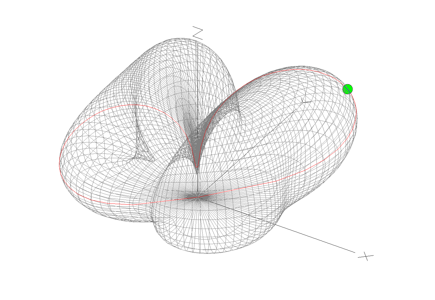
The 3D far field plot for the antenna shows it has a very nice, relatively high gain lobe at just 2 degrees elevation with a number of lower gain lobes higher up.
M0AWS 868Mhz Ground Plane Vertical Antenna 3D Far Field Plot
Looking at the 2D far field plot you can get a better understanding of the radiation pattern and gain figures at various angles. At 2 degrees there is 6.7dBi gain with the next major lobe being at 8 degrees with 4.36dBi gain, far more than I imagined I’d see for such a simple antenna.
M0AWS 868Mhz Ground Plane Vertical Antenna 2D Far Field Plot
Putting the antenna together was easy enough with particular attention being paid to the measurements of both the radials and radiating element. I soldered some lugs to the ends of the 2.5mm diameter solid core wire radials to enable easy attachment to the N Type chassis socket that I decided to use as the base for the antenna. This worked out well and provided a good solid mechanical and electrical connection for the 4 radials.
For the radiating element I used an N Type plug with the vertical 2.5mm solid core wire element soldered to the inner centre pin of the male connector. I also slid a small piece of insulation down the wire to stop it from shorting against the metal outer of the plug and then pushed in a tight rubber plug to stop water ingress.
M0AWS 868Mhz Ground Plane Antenna Close Up
Connecting my VNA I found the antenna was mostly resonant at 790Mhz with an SWR of 2.5:1. I knew this would be the case and that the wires would need a little trimming.
Trimming the wires a couple of times in 1mm nibbles I got the point of resonance up to 868Mhz but, the antenna was still exhibiting a lot of reactance that was keeping the SWR above 2:1. Trimming the radials reduced this slightly but, I could not get an SWR much lower than 1.95:1.
Scratching my head I decided to try moving the radials back up so that they were horizontal rather than at 45 degrees downwards, this had the immediate effect of the SWR dropping to 1.1:1.
M0AWS A rather fuzzy photo of the 868Mhz SWR curve for the GP Antenna
The SWR stays below 1.2:1 from 868Mhz to 871Mhz which is plenty wide enough for the Meshtastic devices. Why there is so much reactance when the radials are bent down at 45 degrees I am not sure, but it was easy enough to resolve.
M0AWS 868Mhz Ground Plane Antenna
The finished antenna is tiny but, seems to work well. Signals from my other nodes are up by 6-9dB according to the SNR reports in the Meshtastic app. I now need to make a couple more of these for my other nodes and then hope to hear some other nodes locally once they appear on air.
Remodelling the antenna in EzNEC with the radials as shown above the gain at 2 degrees is now 5.5dBi, down 1.2dBi but, the overall radiation pattern is identical to the original.
Total cost of the build is about £1 and an hour of my time tinkering with it, bargain!
The off-grid ham shack is fully energy self-sufficient, utilizing solar, wind, and other power sources, with a focus on low current devices for sustainable communication.
Way back in January 2018, I had a goal to “3D print an electronics project case”. I had enrolled in a SolidWorks class at my local community college to learn 3D modeling. Sadly I didn’t complete it, and it remained a goal of mine for several years until I decided to move on to something I might actually finish.
There were a couple of reasons for not completing the goal. The first was a life-threatening illness that left me pretty weak and unable to complete the class I was taking. The second was that the 3D printer I had was more of a toy than a tool, and it was rarely able to print anything successfully.
Even though I didn’t list it as a goal for 2024, I had a growing itch, and decided to replace my original toy printer with a FLASHFORGE Adventurer 5M Pro. The big steps up were a heated platform and full enclosure that allows for better thermal management. In addition, it is blazingly fast, by about a factor of 16, compared to what consumer printers were capable of back in 2018. No longer a toy, this is a tool for a maker.
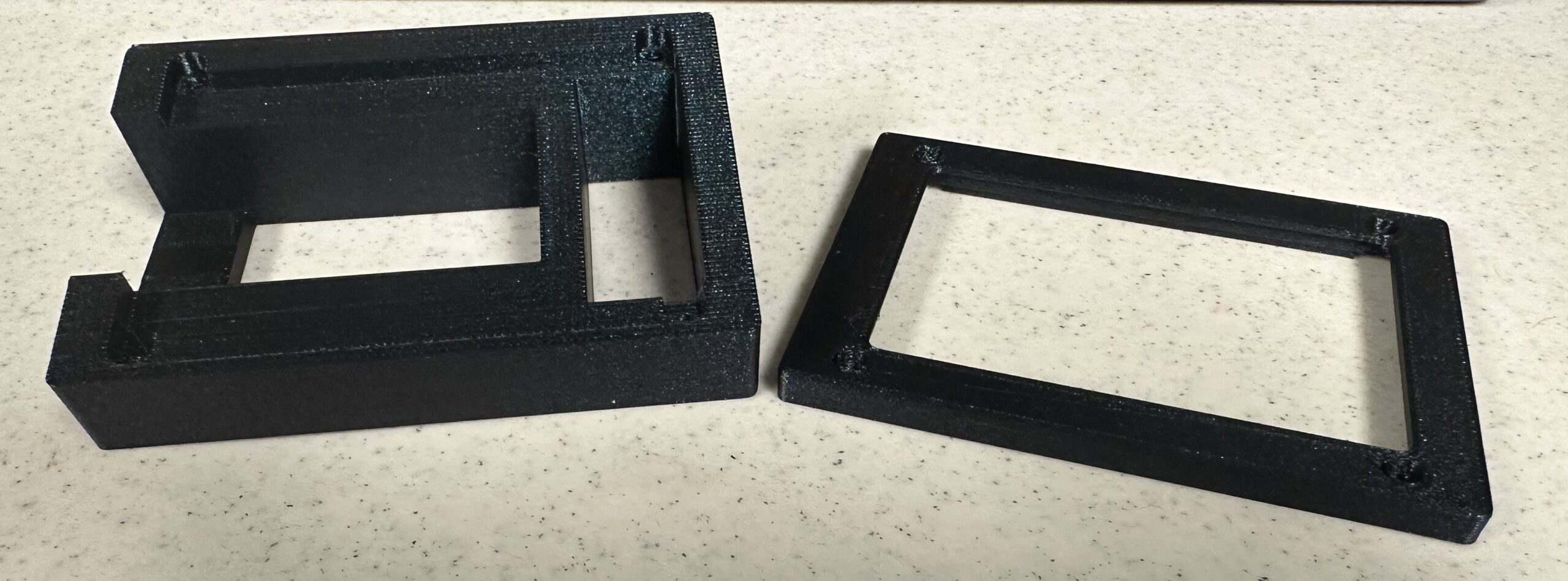
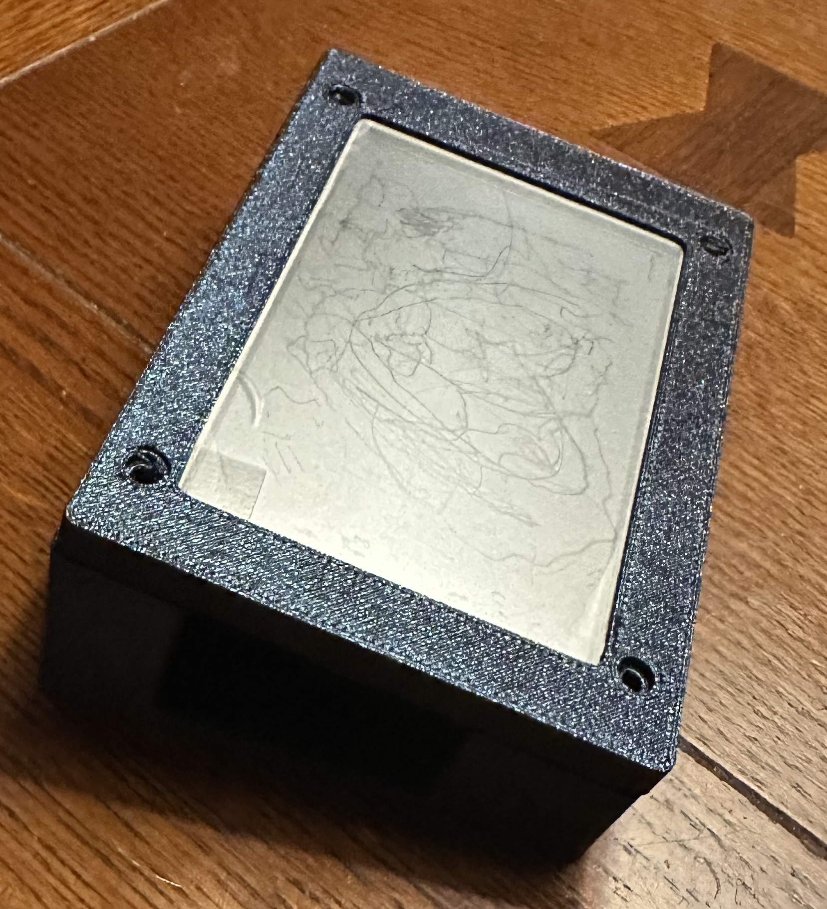
I’m happy to report that after six years, I have finally completed the goal, 3D printing two parts to make an enclosure for a 3.5″ LCD display and an ESP32 processor. I guess I will count this as a “wildcard” replacing any project I don’t complete in 2024.
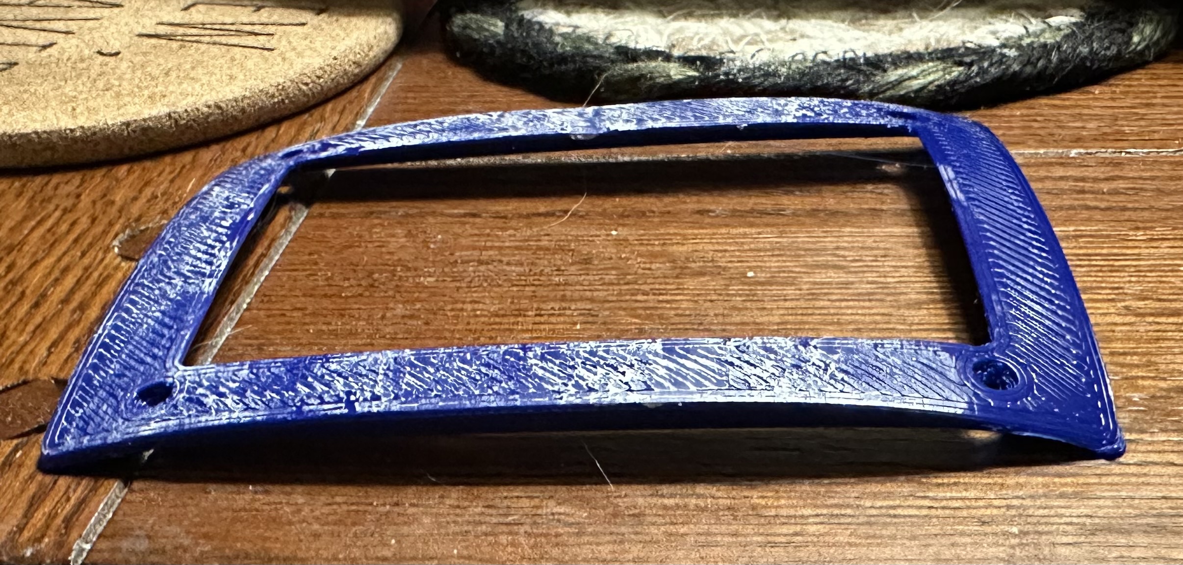
The two parts of the enclosure: The bottom is on the left, and the top on the right.
The enclosure with the LCD visible on the top (4″L x 3″W x 1.5″T)
Winter always brings a desire to do projects of some sort. In fact, throughout the rest of the year, I tend to acquire parts for small projects with the hopes of finishing them during the cold, dark, snowy New England nights. (Perhaps I haven’t been successful for a few years due to climate change – winter in New England is no longer horrible and coma inducing).
I found myself soldering a few 0.1″ connectors onto an Adafruit Feather board a couple of days ago. It was likely the first time I’ve used a soldering iron in a couple of years. While my age has brought on hand tremors, I did manage to get things properly soldered by using sandbags to support my wrist and hands. It took about 15 times longer than it would have a decade ago, but I got it done.
One thing leads to another, and with the Feather board working, it now required something to put it in. I had purchased a low-end 3D printer about six years ago, a da Vinci mini W. It was enough to wet my interest in 3D modeling, and enabled me to take a class in SolidWorks at my local community college (hint – college students get a free license to SolidWorks that is good for 4 years, and the class fee is MUCH lower than what a one year license costs). Anyway, I fired up the printer to attempt to print a case. It was a disaster from start to end, but sort of a fun way to spend a cold afternoon.
The printer hadn’t been used in 5 years, and the same PLA filament sat in the machine all that time, becoming brittle with age and full of moisture. With cleaning and some fiddling, it did spit out some string, and were it not for the cold conditions of the basement where it resides, it might have worked.
What did happen, when I tried printing the cover, was badly warped, as the material pulled off the Kapton tape, and even managed to pull the tape off the platform.
I’ve been wanting to tidy up the cabling to the 12v DC PSU for some time in the radio shack as like many HAMs I have a number of radios/devices that all need a 12v feed but, only two connectors on the front of the PSU. The net result was a birds nest of wires all connected to the PSU making it impossible to disconnect one device without others getting disconnected at the same time.
Looking online I found that many of the HAM outlets stores sell nice little 12v DC distribution boxes that would be ideal however, they’re all priced somewhat high for what they are so, I decided to purchase the parts and make one myself.
Searching on Amazon I found all the necessary parts for less than a quarter of the cost of commercially made units. A couple of days later the parts arrived and sat on my desk in the shack for a few weeks. Yesterday I finally found the time to make a start on the project.
M0AWS home-brew 12v DC Distribution Box
After much drilling and filing I had the necessary holes/slots cut in the plastic box for the 4mm connectors and fuse holders and started wiring them up. Part way through my 30 year old soldering iron decided to die and so I had to stop and wait for a replacement to arrive.
M0AWS completed 12v DC Distribution Box
With the new soldering iron in hand it only took 30mins or so to complete all the joints and I soon had the box together ready to test with my multimeter to ensure I didn’t have any shorts or crossed wires.
With testing complete and fuses in place I connected it up to the PSU and then connected all the devices one by one checking for voltage drops as I went.
M0AWS 12v DC Distribution Box
I now have my CG3000 remote auto ATU, GPSDO, QO-100 ground station and IC-705 all nicely connected in a much tidier fashion than before, all for considerably less than the commercially available alternatives.
Since I put together my Inverted-L antenna and Pi-Network ATU I’ve been having a lot of fun on the low bands.
Getting back onto 160m has been most enjoyable and I’ve now had over 100 ‘Top Band’ contacts with distances covered as far as 3453 Miles into Sosnovoborsk Asiatic Russia.
I must admit I am amazed at the distances achieved on the 160m band as the antenna isn’t very high above ground level when compared to a single wave length on 160m.
M0AWS Inverted-L Antenna View
The Inverted-L antenna at the M0AWS QTH was designed purely around the size of the back garden. Using a couple of 10m Spiderpoles the vertical section of the antenna is 10m tall and the horizontal section is 28m long. Naturally the antenna resonates around 2.53Mhz but, can be tuned to resonate anywhere on any band using the Pi-Network ATU I built that is situated at the base of the vertical section of the antenna.
Looking at the far field plots for the antenna on each band we see that as we move higher in frequency the radiation pattern becomes more complex and the radiation angle gets lower, exactly what we would expect from such an antenna. The antenna runs pretty much North/South in the garden ( X axis on the diagram above) and so we would expect the antenna to radiate East/West (Y axis on the diagram above) however, this isn’t always the case.
M0AWS Inverted-L Antenna 160m 3D Far Field PlotM0AWS Inverted-L Antenna 160m 2D Far Field Plot
(Click Far Field Plots for full screen view)
On 160m the antenna favours the South (-X Axis) and presents some usable high angle gain although, from using the antenna you would never know this to be the case as it seems to have pretty good all round coverage. With the best distance of 3453 Miles being covered to the East into Asiatic Russia the antenna performs well even though the far field plot is slightly biased to the South.
M0AWS Inverted-L Antenna 80m 3D Far Field PlotM0AWS Inverted-L Antenna 80m 2D Far Field Plot
On the 80m band the Inverted-L antenna becomes a cloud warmer and exhibits very high angle radiation. On 80m the antenna is ideal for NVIS Inter-G propagation and is great for rag chewing with other UK/Near EU stations.
M0AWS Inverted-L Antenna 60m 3D Far Field PlotM0AWS Inverted-L Antenna 60m 2D Far Field Plot
Looking at the far field plots for the 60m band once again the antenna provides lots of high angle gain however, there is also some very useable lower angle gain that has proven to be excellent for working long hauls into North America and east into Central Asia. On the 60m band during the day the antenna is excellent for Inter-G chatting, using just 20w-40w I can very easily chat with other UK HAMs even when the band is noisy.
M0AWS Inverted-L Antenna 40m 3D Far Field PlotM0AWS Inverted-L Antenna 40m 2D Far Field Plot
Moving on up to the 40m band we find the far field plot starts to get a little more complex. Looking at the 3D plot you’d think that the antenna favoured the South (-X Axis) however, in reality it favours the NorthWest with both some high and low angle gain. This antenna has proven to be excellent for DXing into North America on 40m but, has also been great for DXing into South America getting great signal reports from stations in Panama at a distance of 5415 Miles. During the day NVIS propagation is excellent and I find I can chat with other UK and near EU stations with ease using just 25w.
M0AWS Inverted-L Antenna 60m/40m Global Coverage
Above is a screen shot from PSKReporter showing stations that have heard me on the 40m and 60m bands. As you can see, global coverage is excellent with stations as far as Australia and New Zealand hearing me on the 40m band and stations on the West Coast USA hearing me on the 60m band. I was also pleased to see I was heard in Africa on both bands, a region of the world I would like to get more contacts from.
M0AWS Inverted-L Antenna 30m 3D Far Field PlotM0AWS Inverted-L Antenna 30m 2D Far Field Plot
On the 30m band the Inverted-L antenna starts to exhibit two lobes with gain to the NorthEast and NorthWest. This makes the antenna ideal for working into the USA and Australia/New Zealand over the North Pole. Working US stations is a breeze with relatively low power and I almost got a contact with New Zealand during the evening greyline but, unfortunately the DX station dropped out before I managed to get my signal report back to him. As time goes on I’m sure the antenna will more than prove itself on the 30m band.
So far I’ve not ventured above the 30m band with the Inverted-L antenna as I’ve really been enjoying access to Inter-G chats on 80m, 40m and 60m and chasing DX on 160m, 60m, 40m and 30m. I need to venture up onto the higher bands before the long winter nights settle in and the higher HF bands close for the winter season.
Looking at the far field plots on the higher HF bands the antenna has huge potential as it provides some nice low angle radiation in useful directions.
M0AWS Inverted-L Antenna 20m 3D Far Field PlotM0AWS Inverted-L Antenna 20m 2D Far Field Plot
On the 20m band the far field plot starts to get much more complex with lobes at many different angles. The main gain lobe is to the NorthEast towards the USA and is at a fairly low angle and so this antenna should be great for working stateside on the 20m band. There are also lobes to the NorthEast and so hopefully working VK/ZL over the pole should also be possible. As I said above I’ve not yet used the antenna above the 30m band and so at this time cannot confirm performance but, it looks promising.
M0AWS Inverted-L Antenna 17m 3D Far Field PlotM0AWS Inverted-L Antenna 17m 2D Far Field Plot
The 17m band also looks promising with a similar far field plot as the 20m band but, with lower angle of maximum radiation and more gain. It will be very interesting to test this antenna on 17m especially since the noise level is below S0 and I can very easily hear the weakest of stations on this band.
M0AWS Inverted-L Antenna 15m 3D Far Field PlotM0AWS Inverted-L Antenna 15m 2D Far Field Plot
Once again the 15m band looks very similar to the 17m band, low angle radiation but, with a slightly more complex far field plot.
M0AWS Inverted-L Antenna 12m 3D Far Field PlotM0AWS Inverted-L Antenna 12m 2D Far Field Plot
The 12m band far field plots continue the theme with the angle of maximum radiation slightly lower than on the 15m band and slightly more gain. This antenna should be great for chasing the DX on the very quiet 12m band.
M0AWS Inverted-L Antenna 10m 3D Far Field PlotM0AWS Inverted-L Antenna 10m 2D Far Field Plot
Finally the 10m band is very similar to the 12m band in that the far field plots show low angle gain albeit with an even more complex radiation pattern.
I originally put this antenna up so that I could work Inter-G on the low bands but, it has proven to be a much more worthy antenna than I originally thought it would be. I need to spend more time with this antenna on the bands above 30m to really see how it performs on the higher HF bands but, so far I’m really pleased with it’s overall performance on all the bands tested to date.
I can highly recommend using FT8 to test new antennas. With PSKReporter and my own NodeRed World Map WSJT-X interface I can see realtime the antenna performance on each band. FT8 is an extremely useful tool when it comes to testing antennas to see if they perform as per the modelling and can often provide some performance surprises!