In my quest to improve my Meshtastic signal range using home-brew antennas I’ve finally put together a neat little ground plane vertical antenna for the 868Mhz ISM band.
The design follows the normal ground plane simplicity using 4 radials and a vertical radiating element albeit on a tiny scale. The radiating element is 82mm long and the radials are each 92mm long.
M0AWS 868Mhz Ground Plane Vertical Antenna
Initially I modelled the antenna at a height of 3m above the ground with the radials tilted downwards at 45 degrees. I took this approach as this is how I have built ground plane verticals for the 70cm band in the past and so I thought I’d try the same approach on the 868Mhz ISM band. (I later found this to be detrimental to tuning!)
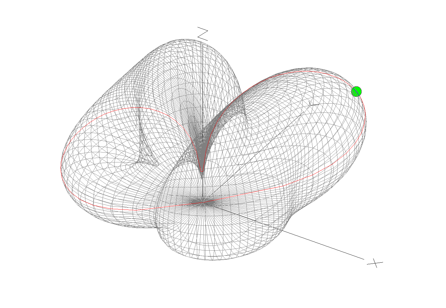
The 3D far field plot for the antenna shows it has a very nice, relatively high gain lobe at just 2 degrees elevation with a number of lower gain lobes higher up.
M0AWS 868Mhz Ground Plane Vertical Antenna 3D Far Field Plot
Looking at the 2D far field plot you can get a better understanding of the radiation pattern and gain figures at various angles. At 2 degrees there is 6.7dBi gain with the next major lobe being at 8 degrees with 4.36dBi gain, far more than I imagined I’d see for such a simple antenna.
M0AWS 868Mhz Ground Plane Vertical Antenna 2D Far Field Plot
Putting the antenna together was easy enough with particular attention being paid to the measurements of both the radials and radiating element. I soldered some lugs to the ends of the 2.5mm diameter solid core wire radials to enable easy attachment to the N Type chassis socket that I decided to use as the base for the antenna. This worked out well and provided a good solid mechanical and electrical connection for the 4 radials.
For the radiating element I used an N Type plug with the vertical 2.5mm solid core wire element soldered to the inner centre pin of the male connector. I also slid a small piece of insulation down the wire to stop it from shorting against the metal outer of the plug and then pushed in a tight rubber plug to stop water ingress.
M0AWS 868Mhz Ground Plane Antenna Close Up
Connecting my VNA I found the antenna was mostly resonant at 790Mhz with an SWR of 2.5:1. I knew this would be the case and that the wires would need a little trimming.
Trimming the wires a couple of times in 1mm nibbles I got the point of resonance up to 868Mhz but, the antenna was still exhibiting a lot of reactance that was keeping the SWR above 2:1. Trimming the radials reduced this slightly but, I could not get an SWR much lower than 1.95:1.
Scratching my head I decided to try moving the radials back up so that they were horizontal rather than at 45 degrees downwards, this had the immediate effect of the SWR dropping to 1.1:1.
M0AWS A rather fuzzy photo of the 868Mhz SWR curve for the GP Antenna
The SWR stays below 1.2:1 from 868Mhz to 871Mhz which is plenty wide enough for the Meshtastic devices. Why there is so much reactance when the radials are bent down at 45 degrees I am not sure, but it was easy enough to resolve.
M0AWS 868Mhz Ground Plane Antenna
The finished antenna is tiny but, seems to work well. Signals from my other nodes are up by 6-9dB according to the SNR reports in the Meshtastic app. I now need to make a couple more of these for my other nodes and then hope to hear some other nodes locally once they appear on air.
Remodelling the antenna in EzNEC with the radials as shown above the gain at 2 degrees is now 5.5dBi, down 1.2dBi but, the overall radiation pattern is identical to the original.
Total cost of the build is about £1 and an hour of my time tinkering with it, bargain!
Since I put together my Inverted-L antenna and Pi-Network ATU I’ve been having a lot of fun on the low bands.
Getting back onto 160m has been most enjoyable and I’ve now had over 100 ‘Top Band’ contacts with distances covered as far as 3453 Miles into Sosnovoborsk Asiatic Russia.
I must admit I am amazed at the distances achieved on the 160m band as the antenna isn’t very high above ground level when compared to a single wave length on 160m.
M0AWS Inverted-L Antenna View
The Inverted-L antenna at the M0AWS QTH was designed purely around the size of the back garden. Using a couple of 10m Spiderpoles the vertical section of the antenna is 10m tall and the horizontal section is 28m long. Naturally the antenna resonates around 2.53Mhz but, can be tuned to resonate anywhere on any band using the Pi-Network ATU I built that is situated at the base of the vertical section of the antenna.
Looking at the far field plots for the antenna on each band we see that as we move higher in frequency the radiation pattern becomes more complex and the radiation angle gets lower, exactly what we would expect from such an antenna. The antenna runs pretty much North/South in the garden ( X axis on the diagram above) and so we would expect the antenna to radiate East/West (Y axis on the diagram above) however, this isn’t always the case.
M0AWS Inverted-L Antenna 160m 3D Far Field PlotM0AWS Inverted-L Antenna 160m 2D Far Field Plot
(Click Far Field Plots for full screen view)
On 160m the antenna favours the South (-X Axis) and presents some usable high angle gain although, from using the antenna you would never know this to be the case as it seems to have pretty good all round coverage. With the best distance of 3453 Miles being covered to the East into Asiatic Russia the antenna performs well even though the far field plot is slightly biased to the South.
M0AWS Inverted-L Antenna 80m 3D Far Field PlotM0AWS Inverted-L Antenna 80m 2D Far Field Plot
On the 80m band the Inverted-L antenna becomes a cloud warmer and exhibits very high angle radiation. On 80m the antenna is ideal for NVIS Inter-G propagation and is great for rag chewing with other UK/Near EU stations.
M0AWS Inverted-L Antenna 60m 3D Far Field PlotM0AWS Inverted-L Antenna 60m 2D Far Field Plot
Looking at the far field plots for the 60m band once again the antenna provides lots of high angle gain however, there is also some very useable lower angle gain that has proven to be excellent for working long hauls into North America and east into Central Asia. On the 60m band during the day the antenna is excellent for Inter-G chatting, using just 20w-40w I can very easily chat with other UK HAMs even when the band is noisy.
M0AWS Inverted-L Antenna 40m 3D Far Field PlotM0AWS Inverted-L Antenna 40m 2D Far Field Plot
Moving on up to the 40m band we find the far field plot starts to get a little more complex. Looking at the 3D plot you’d think that the antenna favoured the South (-X Axis) however, in reality it favours the NorthWest with both some high and low angle gain. This antenna has proven to be excellent for DXing into North America on 40m but, has also been great for DXing into South America getting great signal reports from stations in Panama at a distance of 5415 Miles. During the day NVIS propagation is excellent and I find I can chat with other UK and near EU stations with ease using just 25w.
M0AWS Inverted-L Antenna 60m/40m Global Coverage
Above is a screen shot from PSKReporter showing stations that have heard me on the 40m and 60m bands. As you can see, global coverage is excellent with stations as far as Australia and New Zealand hearing me on the 40m band and stations on the West Coast USA hearing me on the 60m band. I was also pleased to see I was heard in Africa on both bands, a region of the world I would like to get more contacts from.
M0AWS Inverted-L Antenna 30m 3D Far Field PlotM0AWS Inverted-L Antenna 30m 2D Far Field Plot
On the 30m band the Inverted-L antenna starts to exhibit two lobes with gain to the NorthEast and NorthWest. This makes the antenna ideal for working into the USA and Australia/New Zealand over the North Pole. Working US stations is a breeze with relatively low power and I almost got a contact with New Zealand during the evening greyline but, unfortunately the DX station dropped out before I managed to get my signal report back to him. As time goes on I’m sure the antenna will more than prove itself on the 30m band.
So far I’ve not ventured above the 30m band with the Inverted-L antenna as I’ve really been enjoying access to Inter-G chats on 80m, 40m and 60m and chasing DX on 160m, 60m, 40m and 30m. I need to venture up onto the higher bands before the long winter nights settle in and the higher HF bands close for the winter season.
Looking at the far field plots on the higher HF bands the antenna has huge potential as it provides some nice low angle radiation in useful directions.
M0AWS Inverted-L Antenna 20m 3D Far Field PlotM0AWS Inverted-L Antenna 20m 2D Far Field Plot
On the 20m band the far field plot starts to get much more complex with lobes at many different angles. The main gain lobe is to the NorthEast towards the USA and is at a fairly low angle and so this antenna should be great for working stateside on the 20m band. There are also lobes to the NorthEast and so hopefully working VK/ZL over the pole should also be possible. As I said above I’ve not yet used the antenna above the 30m band and so at this time cannot confirm performance but, it looks promising.
M0AWS Inverted-L Antenna 17m 3D Far Field PlotM0AWS Inverted-L Antenna 17m 2D Far Field Plot
The 17m band also looks promising with a similar far field plot as the 20m band but, with lower angle of maximum radiation and more gain. It will be very interesting to test this antenna on 17m especially since the noise level is below S0 and I can very easily hear the weakest of stations on this band.
M0AWS Inverted-L Antenna 15m 3D Far Field PlotM0AWS Inverted-L Antenna 15m 2D Far Field Plot
Once again the 15m band looks very similar to the 17m band, low angle radiation but, with a slightly more complex far field plot.
M0AWS Inverted-L Antenna 12m 3D Far Field PlotM0AWS Inverted-L Antenna 12m 2D Far Field Plot
The 12m band far field plots continue the theme with the angle of maximum radiation slightly lower than on the 15m band and slightly more gain. This antenna should be great for chasing the DX on the very quiet 12m band.
M0AWS Inverted-L Antenna 10m 3D Far Field PlotM0AWS Inverted-L Antenna 10m 2D Far Field Plot
Finally the 10m band is very similar to the 12m band in that the far field plots show low angle gain albeit with an even more complex radiation pattern.
I originally put this antenna up so that I could work Inter-G on the low bands but, it has proven to be a much more worthy antenna than I originally thought it would be. I need to spend more time with this antenna on the bands above 30m to really see how it performs on the higher HF bands but, so far I’m really pleased with it’s overall performance on all the bands tested to date.
I can highly recommend using FT8 to test new antennas. With PSKReporter and my own NodeRed World Map WSJT-X interface I can see realtime the antenna performance on each band. FT8 is an extremely useful tool when it comes to testing antennas to see if they perform as per the modelling and can often provide some performance surprises!
I’ve had this antenna model for ages now but, never got round to putting it onto the website until Alex, GM5ALX was talking about making one the other day whilst chatting on the QO-100 satellite.
The 20m band delta loop follows exactly the same design principles as all the other delta loop designs I’ve already put on the website. They are designed such that they present a 50 ohm impedance at the feed point and thus have no requirement for complex impedance matching circuits/transformers.
M0AWS 20m Band Delta Loop Antenna – Antenna View
The dimensions for the antenna are as follows:
Wire 1 – Horizontal exactly 1m above the ground for its entire 10.2m length. Wires 2 & 3 are exactly 6.18m long each with the top being 4.5m above the ground.
M0AWS 20m Band Delta Loop Antenna – 3D Far Field Plot
The 3D far field plot shows a typical delta loop radiation pattern with the maximum radiation through the loop and a deep null in the centre.
M0AWS 20m Band Delta Loop Antenna – 2D Far Field Plot
The 2D elevation plot shows that the antenna will give a maximum gain of -0.79dBi at 30 degrees when used over average/poor soil types. If like me you use your Delta Loop antennas on the beach then the antenna will present considerably more gain as it will benefit from the salt water reflection.
If you want to lower the angle of maximum radiation and increase the gain over average ground just raise the antenna up so that the top is around 7m above ground. This will give a much lower angle of radiation and improve the gain figure by 2-3dBi. Don’t forget that if you raise the antenna the point of resonance will also rise in frequency and so you may need to shorten the wires a little to get the point of resonance back to where you want it.
The SWR plot shows that the antenna will have a fairly wide bandwidth and match to 50 ohm coax extremely well. The antenna is designed to be fed in one of the lower corners via a 1:1 balun for best results.
M0AWS 20m Band Delta Loop Antenna – SWR Curve
Summary:
Total Wire Length: 16.38m Horizontal Wire Length: 10.2m @ 1m above ground Diagonal Wire Lengths: 6.18m Wire Dia: 2.5mm Height at Centre: 4.5m Feed Type: 1:1 Balun in bottom corner (Can use coax if necessary) Impedance: 50 Ohm SWR: <1.5:1 at resonance