After initially finding that I couldn’t tune the 868Mhz ground plane antenna with the radials bent down at 45 degrees I decided to experiment to find out why.
Initially I had the radials connected to the 4 corners of the base of the chassis mount N Type socket. This works great if you have the radials completely horizontal and gives an SWR of 1.1:1 but, with the radials bent down at 45 degrees the best SWR is around 2:1.
M0AWS 868Mhz Ground Plane Antenna Close Up
Removing the radials from the base of the N Type chassis socket and soldering them to the outer of the N Type plug at the same level as the feed point for the radiating element I found that an almost perfect SWR can be achieved very easily.
M0AWS 868Mhz Antenna with radials soldered to the N Type Plug
It seemed weird to me that such a small change could have such a big effect on the obtainable SWR for the antenna but, as can be seen in the image below with the radials soldered to the N Type plug and bent downwards I immediately got an SWR of 1.07:1 and a much wider SWR curve.
M0AWS 868Mhz Antenna SWR curve with radials soldered to N Type plug.
By making my own antennas I’m learning a lot about antenna design for the 800-900Mhz frequency range. Minor changes seem to have a much bigger impact than they do at much lower frequencies.
In my quest to improve my Meshtastic signal range using home-brew antennas I’ve finally put together a neat little ground plane vertical antenna for the 868Mhz ISM band.
The design follows the normal ground plane simplicity using 4 radials and a vertical radiating element albeit on a tiny scale. The radiating element is 82mm long and the radials are each 92mm long.
M0AWS 868Mhz Ground Plane Vertical Antenna
Initially I modelled the antenna at a height of 3m above the ground with the radials tilted downwards at 45 degrees. I took this approach as this is how I have built ground plane verticals for the 70cm band in the past and so I thought I’d try the same approach on the 868Mhz ISM band. (I later found this to be detrimental to tuning!)
The 3D far field plot for the antenna shows it has a very nice, relatively high gain lobe at just 2 degrees elevation with a number of lower gain lobes higher up.
M0AWS 868Mhz Ground Plane Vertical Antenna 3D Far Field Plot
Looking at the 2D far field plot you can get a better understanding of the radiation pattern and gain figures at various angles. At 2 degrees there is 6.7dBi gain with the next major lobe being at 8 degrees with 4.36dBi gain, far more than I imagined I’d see for such a simple antenna.
M0AWS 868Mhz Ground Plane Vertical Antenna 2D Far Field Plot
Putting the antenna together was easy enough with particular attention being paid to the measurements of both the radials and radiating element. I soldered some lugs to the ends of the 2.5mm diameter solid core wire radials to enable easy attachment to the N Type chassis socket that I decided to use as the base for the antenna. This worked out well and provided a good solid mechanical and electrical connection for the 4 radials.
For the radiating element I used an N Type plug with the vertical 2.5mm solid core wire element soldered to the inner centre pin of the male connector. I also slid a small piece of insulation down the wire to stop it from shorting against the metal outer of the plug and then pushed in a tight rubber plug to stop water ingress.
M0AWS 868Mhz Ground Plane Antenna Close Up
Connecting my VNA I found the antenna was mostly resonant at 790Mhz with an SWR of 2.5:1. I knew this would be the case and that the wires would need a little trimming.
Trimming the wires a couple of times in 1mm nibbles I got the point of resonance up to 868Mhz but, the antenna was still exhibiting a lot of reactance that was keeping the SWR above 2:1. Trimming the radials reduced this slightly but, I could not get an SWR much lower than 1.95:1.
Scratching my head I decided to try moving the radials back up so that they were horizontal rather than at 45 degrees downwards, this had the immediate effect of the SWR dropping to 1.1:1.
M0AWS A rather fuzzy photo of the 868Mhz SWR curve for the GP Antenna
The SWR stays below 1.2:1 from 868Mhz to 871Mhz which is plenty wide enough for the Meshtastic devices. Why there is so much reactance when the radials are bent down at 45 degrees I am not sure, but it was easy enough to resolve.
M0AWS 868Mhz Ground Plane Antenna
The finished antenna is tiny but, seems to work well. Signals from my other nodes are up by 6-9dB according to the SNR reports in the Meshtastic app. I now need to make a couple more of these for my other nodes and then hope to hear some other nodes locally once they appear on air.
Remodelling the antenna in EzNEC with the radials as shown above the gain at 2 degrees is now 5.5dBi, down 1.2dBi but, the overall radiation pattern is identical to the original.
Total cost of the build is about £1 and an hour of my time tinkering with it, bargain!
The Heltec ESP32 v3 LORA devices have a coil type Bluetooth/Wifi antenna on the PCB from the factory. This antenna doesn’t work particularly well and has very limited range so, I decided to do something about it.
Getting out the calculator a quarter wave at 2400Mhz is 29.7mm. Looking at the coil antenna on the PCB I decided the best way to connect the new antenna would be to solder it to the coil of the existing antenna. This would short out the coil completely whilst creating a solid mount point for the new antenna.
After a little measuring I decided to use a 31mm long piece of 1.5mm hard core mains cable for the new antenna. I stripped back the insulation from one end of the wire so that the exposed copper wire was exactly the length to short across all the windings of the coil antenna on the PCB.
Attaching replacement Bluetooth Antenna to the Heltec ESP32 v3 Device
Attaching the the wire to the coil was easy enough to do but, it’s worth pointing out that you need to be quick so that the heat doesn’t transfer down onto the PCB desoldering the coil antenna from the device.
Whilst tinkering with the Bluetooth antenna I decided I would also make a neat little quarter wave 868Mhz vertical antenna for this device whilst I had it all apart. This is my Meshtastic node-2 and it’s sole purpose is to allow me to use my iPad to send/receive messages via bluetooth which are then forwarded on to my base node-1 in the house. Node-1 is connected to the house wifi and the Meshtastic MQTT server. This combination allows me to message people on the mesh even though there are no local nodes within RF range.
Running the numbers for the 868Mhz antenna the vertical will need to be around 82.1mm long with a radial of similar length. I had to hand a very nice SMA to N Type chassis mount socket that would be ideal to mount the antenna to the case. I drilled out the holes in the case, measured out the wires and attached it all to the case. Connecting the antenna to the N Type socket I connected my VNA and set about tuning the antenna to resonance.
M0AWS Hidden Radial for the 868Mhz Heltec Antenna
Squeezing the radial and SMA connector into the case I realised I really could do with a 90 degree SMA connector so, I quickly ordered one from Amazon which will be delivered tomorrow. Connecting up my VNA, I had to trim the antenna down to get it to resonance. The SWR ended up at 1.2:1 which is ideal. I ended up cutting off more wire than I thought I would to get the antenna to resonance but, this is due to the extra capacitance caused by the insulation on the wire. If I had used bare copper wire then I wouldn’t of had to cut so much off. I eventually ended up with around 72.9mm of wire for both the antenna and radial.
M0AWS Heltec ESP32 v3 Device with replacement Bluetooth and 868Mhz Antennas
Putting the device back into the case and connecting the USB battery the device fired up and immediately connected to my node in the house. Checking the signal strength of node-1 in the house I could see a 7dB increase in signal strength compared to the little wire antenna that comes with the device. This is a significant improvement for such a simple antenna and well worth the effort.
Next I had to drill a hole in the front of the Heltec case so that the Bluetooth antenna could poke out the front and be bent up vertically. This worked out really well and improved the Bluetooth range massively.
M0AWS Completed alterations to the Heltec ESP32 v3 antennas
Putting the node back in the house and taking my iPad down to the end of the garden some 30m away I could instantly connect to the device via Bluetooth from my iPad, something I’d not been able to do prior to adding the new antennas. I can now use the Heltec device via Bluetooth from anywhere in the house or garden making it much more accessible.
It’s amazing the difference an hour and two little pieces of wire can make to these devices and is well worth the effort.
I recently put up a 38m Inverted-L antenna (10m vertical/28m horizontal) and tuned it on the 160m band using a home-brew Pi-Network ATU. It’s working great on top band and I’m really pleased with performance so far.
I decided today that it would be good to try the inverted-L out on some of the other low bands too. Since my other HF antenna is a large vertical that’s great for DXing but, terrible for Inter-G I thought perhaps the Inverted-L would fill the inter-G gap.
M0AWS Pi-Network ATU using my JNCRadio VNA to find the ATU setting for each band
Having recently purchased a JNCRadio VNA from Martin Lynch and Sons it made tuning the ATU for each band really easy. When it comes to antenna resonance I like my antennas to have an SWR of less than 1.2:1. With the VNA connected it is really easy to tune the antenna for a 1:1 SWR on a particular frequency, make a note of the tune information and then move to the next frequency and start again.
M0AWS Pi-Network ATU Inductor with turns countM0AWS Pi-Network ATU Capacitor 1 and 2 settings
I marked up each turn on the large copper inductor so I could record the position of the input wire onto the inductor. I then added some markings on the two capacitors of the Pi-Network ATU for the resonance points on each band/frequency I wanted to resonate the antenna on.
M0AWS Pi-Network ATU settings noted for each band
After about 40mins I had all the settings recorded on a pad ready for testing from the shack end of the coax run. Connecting my Yaesu FTDX10 to the coax I ran through each band setting checking the SWR as I went. All bands tuned up perfectly 160m through 30m and receiving of Inter-G on the bands that were active was excellent.
Wanting to test the antenna on 40m for the first time I found Nick, M7NHC calling CQ and gave him a call using just 5w output. He came straight back to me and we had a quick chat.
Nick was using an Icom IC-7300 using just 10w into an end-fed long wire from Eastbourne down on the south coast so, we were both QRP. Nick was a 5/7 with QSB and he gave me a 5/8 with QSB, not bad at all consider how much power we were using.
I’m hoping to have a chat with some of the guys from the Matrix this evening on 60m SSB so, it will be interesting to see how the antenna performs on 5Mhz.
Since setting up the new HAM station here in the UK the one band I’ve not yet got back onto is 160m, one of my most favourite bands in the HF spectrum and one that I was addicted to when I live in France (F5VKM).
Having such a small garden here in the UK there is no way I can get any type of guyed vertical for 160m erected and so I needed to come up with some sort of compromise antenna for the band.
Only being interested in the FT4/8 and CW sections of the 160m band I calculated that I could get an inverted-L antenna up that would be reasonably close to resonant. It would require some additional inductance to get the electrical length required and some impedance matching to provide a 50 Ohm impedance to the transceiver.
Measuring the garden I found I could get a 28m horizontal section in place and a 10m vertical section using one of my 10m spiderpoles. This would give me a total of 38m of wire that would get me fairly close to the quarter wave length.
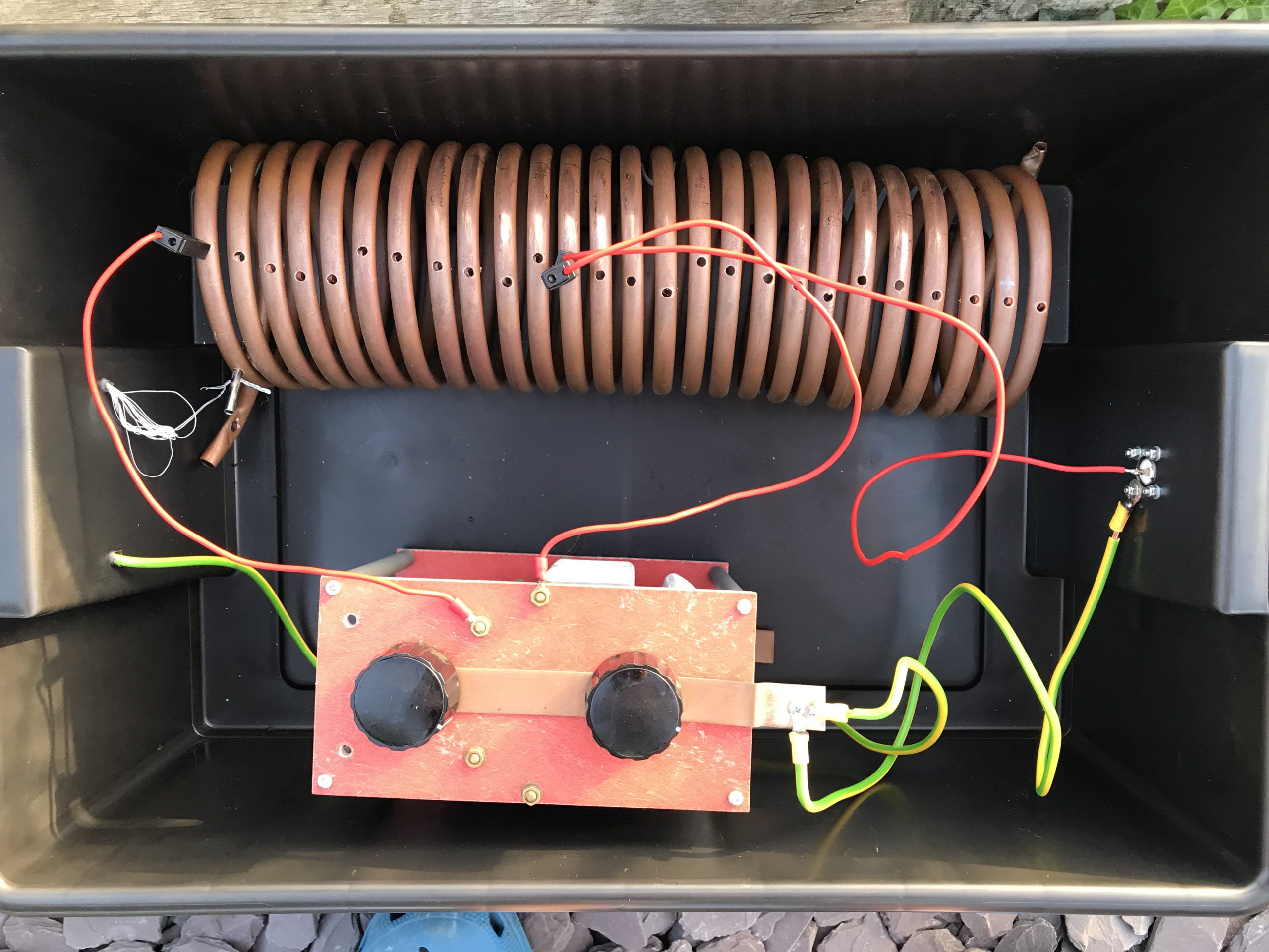
For impedance matching I decided to make a Pi-Network ATU. I’ve made these in the past and found them to be excellent at matching a very wide range of impedances to 50 Ohm.
M0AWS Homebrew Pi-Network ATU
Since I still had the components of the Pi-Network ATU that I built when I lived in France I decided to reuse them as it saved a lot of work. The inductor was made from some copper tubing I had left over after doing all the plumbing in the house in France and so it got repurposed and formed into a very large inductor. The 2 x capacitors I also built many years ago and fortunately I’d kept locked away as they are very expensive to purchase today and a lot of work to make.
Getting the Inverted-L antenna up was easy enough and I soon had it connected to the Pi-Network ATU. I ran a few radials out around the garden to give it something to tune against and wound a 1:1 choke balun at the end of the coax run to stop any common mode currents that may have appeared on the coax braid.
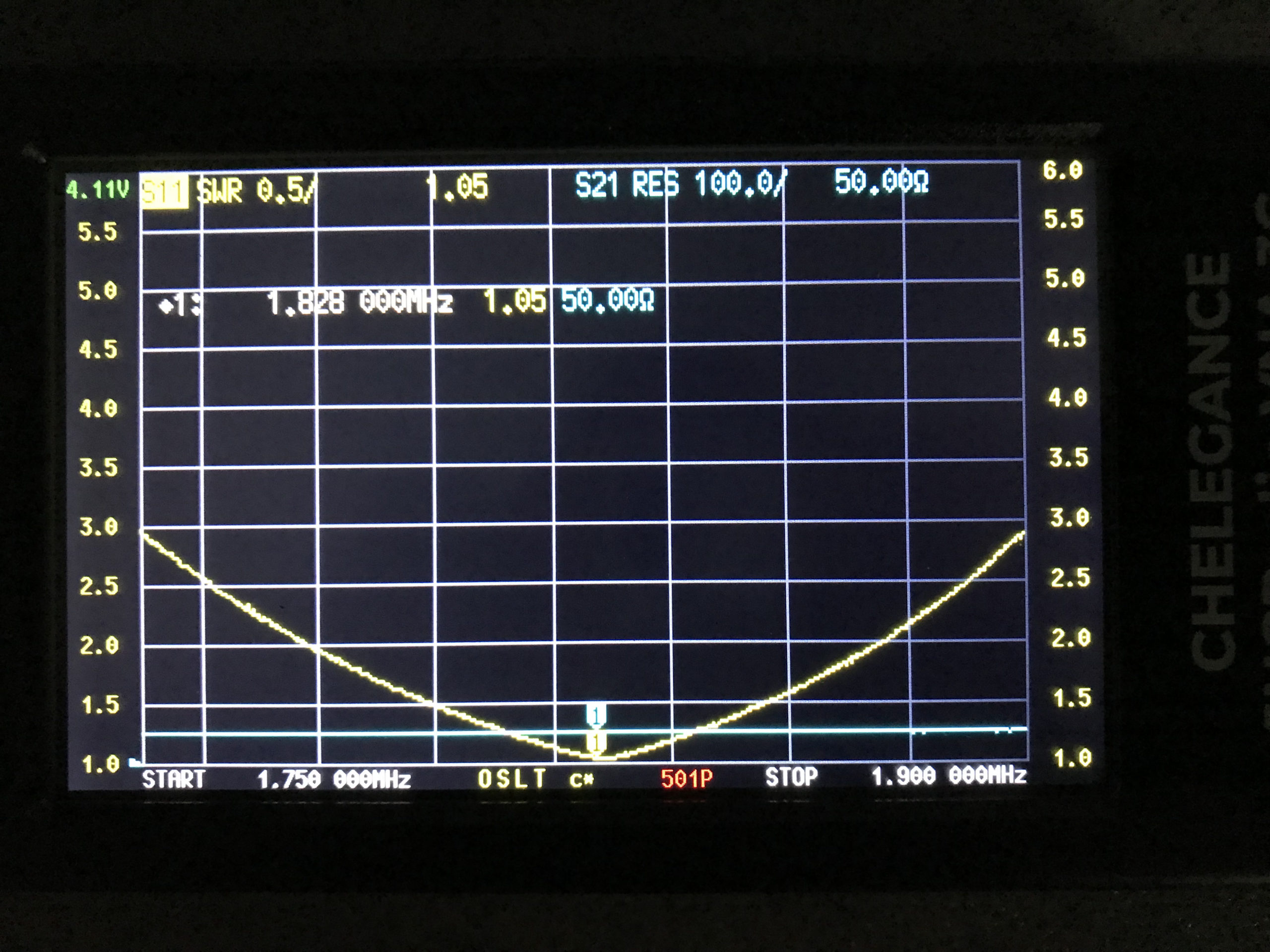
Connecting my JNCRadio VNA I found that the Inverted-L was naturally resonant at 2.53Mhz, not too far off the 1.84Mhz that I needed. Adding a little extra inductance and capacitance via the ATU I soon had the antenna resonant where I wanted it at the bottom of the 160m band.
M0AWS 160m Inverted L Antenna SWR Curve
With the SWR being <1.5:1 across the CW and FT8 section of the band I was ready to get on 160m for the first time in a long.
Since it’s still summer in the UK I wasn’t expecting to find the band in very good shape but, was pleasantly surprised. Switching the radio on before full sunset I was hearing stations all around Europe with ease. In no time at all I was working stations and getting good reports using just 22w of FT8. FT8 is such a good mode for testing new antennas.
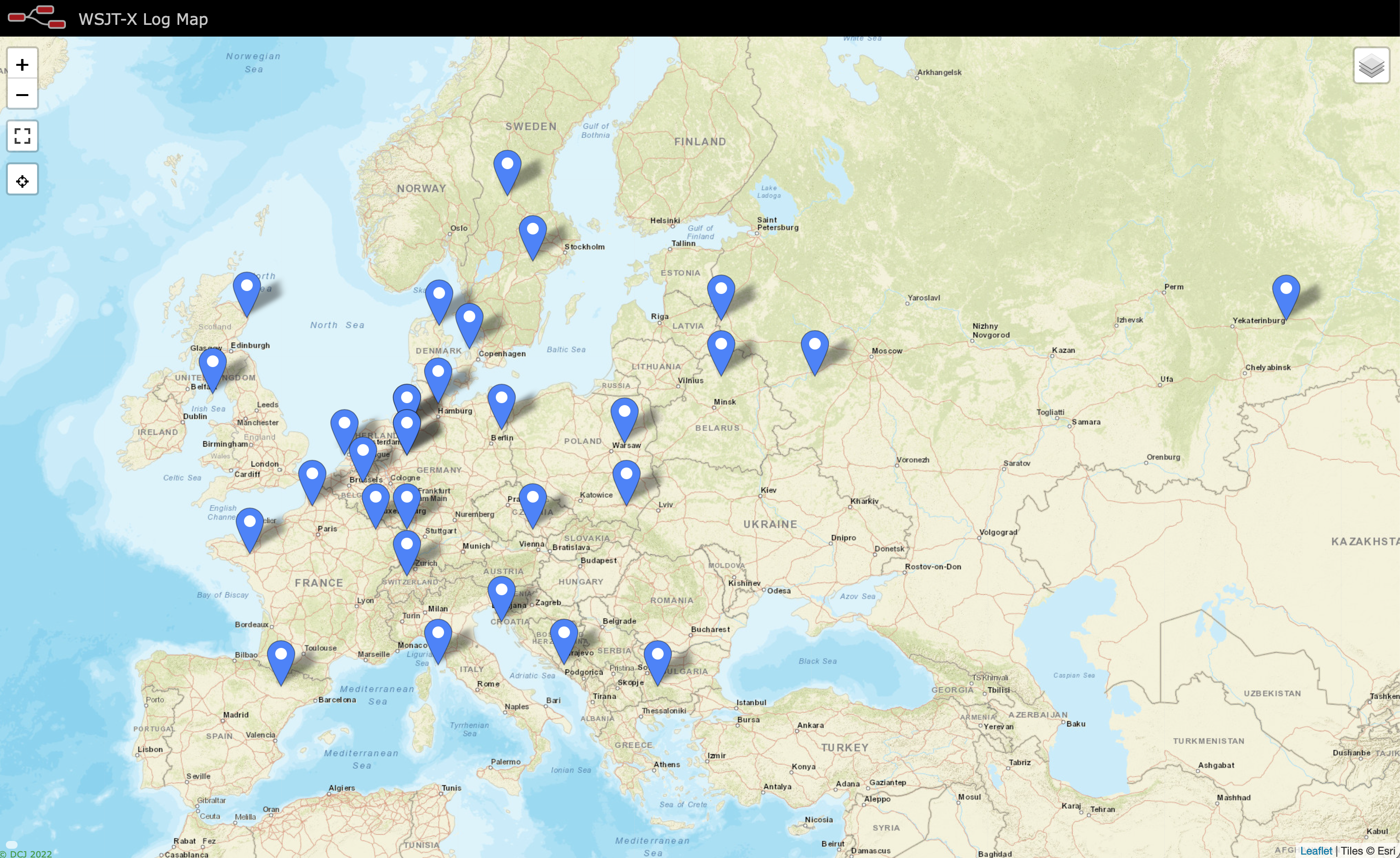
As the sky got darker the distance achieved got greater and over time I was able to work into Russia with the longest distance recorded being 2445 Miles, R9LE in Tyumen Asiatic Russia.
In no time at all I’d worked 32 stations taking my total 160m QSOs from 16 to 48. I can’t wait for the long, dark winter nights to see how well this antenna really performs.
M0AWS Map showing stations worked on 160m using Inverted L Antenna
The map above shows the locations of the stations worked on the first evening using the 160m Inverted-L antenna. As the year moves on and we slowly progress into winter it will be fun to start chasing the DX again on the 160m band..
UPDATE 6th October 2023. Been using the antenna for some time now with over 100 contacts on 160m. Best 160m DX so far is RV0AR in Sosnovoborsk Asiatic Russia, 3453 Miles using just 22w. Pretty impressive for such a low antenna on Top Band.
Since purchasing my Retevis RT85 2m/70cm handheld radio I’ve noticed that it seems rather deaf when using the antenna that came with the radio and isn’t as strong into the local repeaters as I imagined it would be.
Considering the local 2m and 70cm repeater isn’t that far from my QTH and there is pretty much a clear line of site view in the direction of the repeater I was somewhat surprised that on 70cm the repeater never breaks the squelch, even if it is set on it’s lowest setting of zero.
M0AWS Retevis RT85 dual band VHF/UHF Handheld Radio
Connecting my home made end fed dual band vertical dipole at 10m above ground the performance of the radio improves drastically as one would expect.
Having recently purchased a JNCRadio VNA 3G antenna analyser I decided to connect the Retevis supplied antenna to the analyser and see what the resonance was like on the two bands.
The antenna is labelled as 136-174Mhz and 400-470Mhz. This is an extremely wide frequency range for such a small antenna and clearly isn’t going to perform that well over such a wide bandwidth.
Connecting the antenna to the VNA and setting the stimulus frequency range to 144-148Mhz I found that the SWR curve of the antenna wasn’t particularly good.
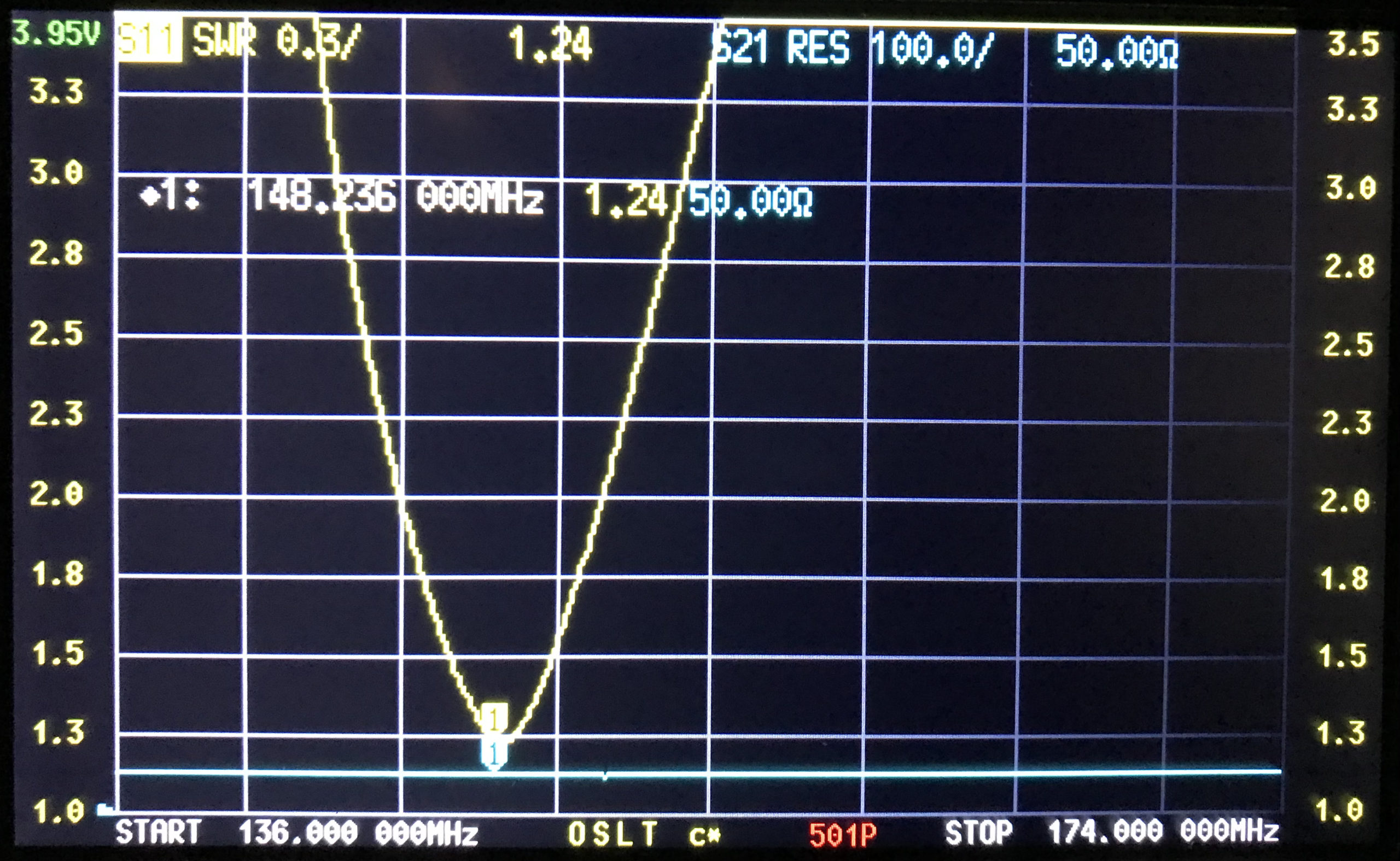
M0AWS Retevis RT85 Antenna SWR Curve 2m
As shown above the SWR curve on the 2m Band is pretty poor. At 144.0Mhz it’s just over 3:1, at 145.496 (closest I could get to the 145.500 calling channel) the SWR is still 2.1:1. The antenna doesn’t really get close to resonance until 148Mhz where the SWR is 1.46:1.
With an SWR this high the radio will almost certainly be reducing the O/P power considerably to protect the PA stage from over heating due to so much power be reflected back into the transmitter. This explains the poor performance when using 2m repeaters locally and the somewhat limited range when using the OEM supplied antenna.
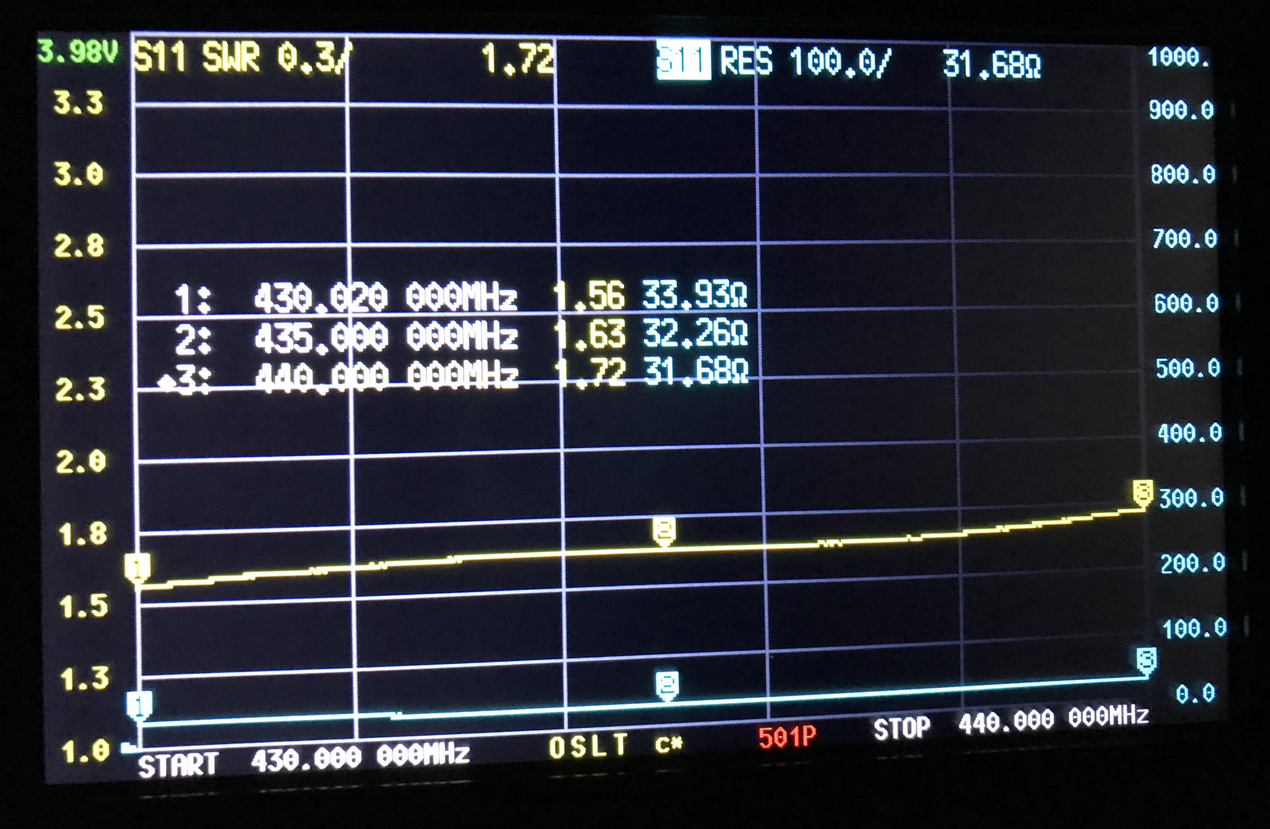
Looking at the SWR curve on the 70cm band, the antenna is much closer to resonance than it is on the 2m band but, it’s still not perfect.
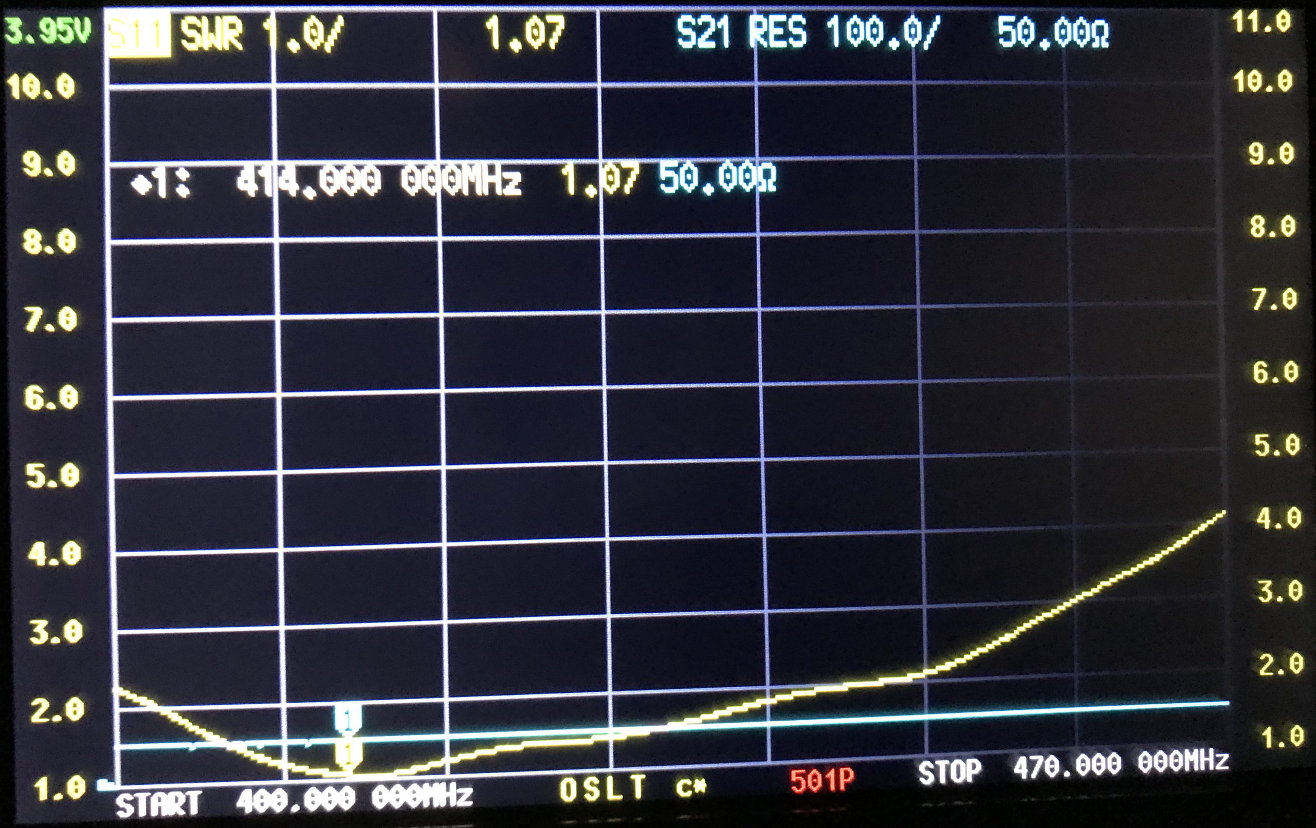
M0AWS Retevis RT85 Antenna SWR Curve 70cm
At 430Mhz the SWR is 1.56:1, at 435Mhz 1.63:1 and 440Mhz 1.72:1. Since the antenna is much closer to resonance on the 70cm band I would expect it to perform better than it does.
Looking at the SWR curves over the entire supported frequency range of 136-174Mhz and 400-470Mhz, there is only one point of resonance on VHF around 148Mhz and on UHF around 400Mhz.
With such disappointing performance on both VHF and UHF I’ve decided to investigate making my own 2m/70cm antenna for the handheld to see if I can improve both the SWR on each band and the overall performance of the radio.