Curious about what you can hear on shortwave ham radio? This video is a brief survey of the diverse world of communications on the shortwave spectrum. Expand your radio horizons and enhance your emergency communication preparedness by tuning in to the world of shortwave ham radio. If you’ve started delving into radio communications beyond local […]
We’ve recently added a new room to the Matrix HAM Radio Space for Digital Voice modes as this was an area of interest that didn’t really fit into any of the other rooms.
The new Digital Voice room has attracted a lot of attention from members, with a lot of the focus being on the AllStarLink system. Michael, DK1MI built an AllStarLink node in the cloud for us all to use for Matrix Nets and so I decided I had to get in on the fun.
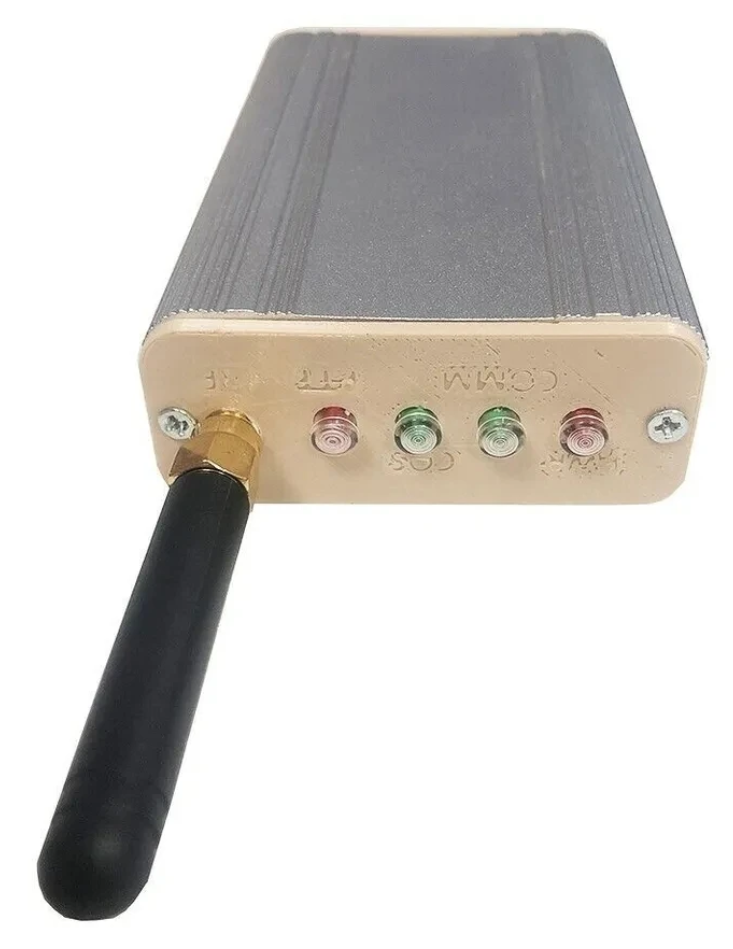
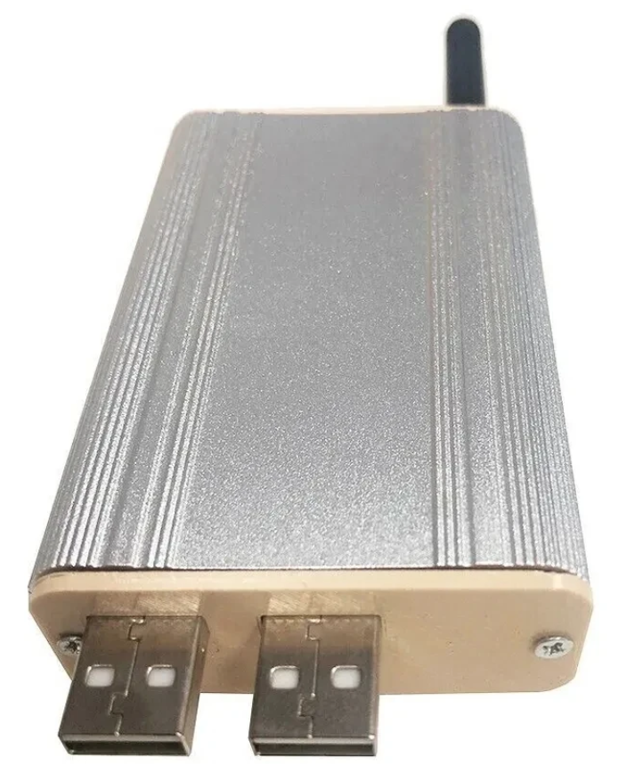
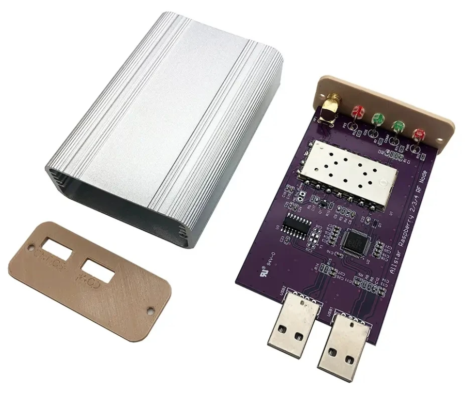
Jumbospot SHARI SA818 Amateur Radio AllStarLink Radio Interface Front Panel ViewJumbospot SHARI SA818 Amateur Radio AllStarLink Radio Interface Rear ViewJumbospot SHARI SA818 Amateur Radio AllStarLink Radio Interface stripped down View
The two USB connectors on the SHARI device are position such that they plug into two of the available 4 USB ports on the RaspberryPi without the need for cables. This keeps the whole solution together in one neat package.
Before you start you will need to obtain a node number and secret (password) from the AllStarLink Portal. To get this you will need to provide proof to the AllStarLink administrators that you are a licensed Amateur Radio (HAM) operator. This is done by uploading a copy of the first page of your HAM licence to the website for the admin team to check. This can take 24hrs to be completed so make sure you get this all done before trying to build your node. You cannot build a node successfully without a node number and secret.
Of course you will also need a transceiver that can operate on the 438.800Mhz frequency or other frequency of your choice on the 2m or 70cm HAM band.
You will also need to open port 4569 on your internet router and setup port forwarding to the IP Address that you will be using on your RaspberryPi node. It’s important to use a static IP Address on your RaspberryPi.
There are quite a few different Linux based operating system (O/S) images that are available for the RaspberryPi devices that have been specifically tailored for the AllStarLink node and include all the necessary software and library packages out the box.
Once downloaded you need to burn the ISO image onto a suitable SD card for your RaspberryPi. I use BalenaEtcher as it’s extremely quick and reliable at burning ISO images to SD cards.
Of course if you are a hardline Linux command line junkie you can always use dd to create the SD card.
Once you’ve got your O/S onto your SD card, slot it into your RaspberryPi making sure your SHARI device is connected to the two USB ports and then power it up. Make sure you have a good PSU for the RaspberryPi as the two devices together draw around 3A of current during the transmit cycle. (I use a 3.6A PSU from Amazon).
The default login for the Raspbian O/S is shown below. Login via SSH and configure your RaspberryPi for your local network. It’s important to use a static IP Address configured either directly on the RaspberryPi or via DHCP in your router.
Next you need to change directory into the asterisk config file directory using the command shown below:
cd /etc/asterisk
In this directory you will find all the default config files that come as part of the distro. For this build we’re not going to use them and so we need to move them out of the way ready for a set of config files that have already been configured correctly.
Using the following commands create a new directory, move into that new directory and then move all the unwanted configuration files into it:
mkdir ORIGINAL-CONF-FILES
cd ./ORIGINAL-CONF-FILES
mv ../*.conf ./
ls -la
cd ../
You should now be back in the /etc/asterisk directory which will now be empty apart from the custom directory which we left in place.
You now need to copy the correctly configured configuration files into the /etc/asterisk directory. Start by downloading the zip file containing the new configuration files
Once downloaded, copy the .zip file into the repeater users home directory (/home/repeater) using either scp on the Linux command line or if using Windows you can use the FileZilla Client in SFTP mode using the login details above.
Once you have the .zip file in the repeater user’s home directory you need to copy the file into the /etc/asterisk directory as user root:
The gpioBASH script and configuration details were supplied by Mark, G1INU in the Digital Voice room on the Matrix. It adds the COS light functionality to the setup. The COS light will now light every time the SA818 hears RF on the input.
The next thing you need to do is configure the SA818 radio device in the SHARI. The script I used was originally from https://wiki.fm-funknetz.de/doku.php?id=fm-funknetz:technik:shari-sa818 all I’ve done is change the entries to switch off CTCSS and changed the frequency to 438.800Mhz. Configuring the SA818 is done by running the SA818-running.pyPython programme that you moved into the repeater user home directory. Making sure you are still user root, run the following commands:
cd /home/repeater
./SA818-running.py
At this point your SHARI SA818 device will be configured to operate on 438.800Mhz and CTCSS will be disabled.
If you want to change the frequency or enable and set a CTCSS tone to access the node you will need to edit the Python programme using your favourite text editor and change the entries accordingly. Once changed rerun the program as shown above and your SHARI will be reconfigured to your new settings.
Next you need to move the allmon.ini.php file into the correct directory so that it enables access to the Allstar Monitor web page on the device so that you can manage connecting/disconnecting nodes. Use the following commands as user root to achieve this:
The allmon.ini.php file needs to have your node name entered into it for it to work correctly. As user root, change directory and edit the file using your favourite editor.
cd /var/www/html
Using your text editor, search for the line starting [XXXXX] and change the XXXXX to your node number. Save the change and exit the file.
At this point you are almost complete, all that is left to do is add your node number and node secret into the appropriate configuration files in the /etc/asterisk directory.
Since I am a Linux command line junkie I use vi to edit all the configuration files on the command line as user root, but you can use any editor of your choice.
cd /etc/asterisk
Start with the extensions.conf file. Search for the line starting with NODE = and delete the XXXXX entry and insert your node number. Save the file and edit it.
Next you need to edit the iax.conf file. This time search for the line starting with register= and change the XXXXX for your node number and the YYYYYYYYYYYY for your node secret. Be careful not to accidentally delete any other characters in the lines otherwise it will corrupt the configuration file.
In the same file search for the two lines that start with secret = and change the YYYYYYYYYYYY for your node secret. Once you have changed both of the secret entries, save and exit the file.
The final file to edit is the rpt.conf file. Once again open the file using your favourite editor and search for the line starting with XXXXX = radio@127.0.0.1:4569/XXXXX, change the XXXXX entries for your node number making sure not to delete any other characters next to the XXXXX entries.
Further down in the same file there is a line that starts with [XXXXX], once again change the XXXXX for your node number making sure to keep the square brackets at each end of the node number as you edit it.
Finally move down to the very bottom of the file and find the two lines that start with /home/repeater/gpio, once again change the XXXXX entries for your node number.
Once this is done, save and exit the file. At this point your node should be fully configured and will only require a reboot to get it working.
As user root, reboot your raspi using the reboot command.
reboot
Once your raspi comes back online, login using SSH as user repeater and then become root user using the sudo command detailed above.
You now need to create the admin user password for the Allstar Monitor web page on the device. This is done using the following commands as user root:
cd /var/www/html/
htpasswd -c .htpasswd admin
You will be asked to enter a password twice for the admin user, make sure you make a note of this password as you will need it to login to the web page.
Once this is done your configuration is complete, logout from the terminal session by entering exit twice (once to logout as user root and another to logout as user repeater).
Using your favourite web browser enter the IP Address of your raspi into the URL bar as shown below:
http://<Your-Raspi-IP>/allmon2
Note: remove the <> from the URL once you have entered the required information.
Once this is done you should be presented with your node control panel as shown below.
First visit to the AllStar Monitor Web Page
Login using Admin and the password you set above and you are now ready to start using your node.
It’s a good idea to connect to node 55553 which is a parrot test node to check your audio levels. you can do this by entering the node into the field at the top left and pressing the connect button.
M0AWS AllStarLink Node 61928 connected to 55553 Parrot
Once connected, tune your radio to 438.800Mhz FM and transmit a test message using your callsign and test123, or something similar. The parrot will then play your recording back to you so that you can hear how you sound. It will also comment on your audio level as to whether it is OK or not.
You are now connected to AllStarLink network and have the world at your finger tips. Below is a small list of nodes in the UK, Australia and America to get you started chatting with other HAMs via your node.
55553	ASL Parrot for testing
41522	M0HOY HUBNet Manchester, UK
60349	VK6CIA 439.275 Perth, Western Australia
51077	VK6SEG South West Hub B Albany WA
2167	M0JKT FreeSTAR UK HUB 2 freestar.network
53573	NWAG NW AllStar Group Lancashire, UK
27339	East Coast Hub Wilmington NC USA
M0AWS AllStarLink Node 61928 sitting on the equipment rack
Thanks to Michael, DK1MI for building and hosting the Matrix HAM Radio Space AllStarLink Node (57881) and getting us all kicked off into the world of AllStarLink!
We hope to be having regular Matrix Net’s on the node soon for all Matrix members and visitors. We’ll organise days/times via the Digital Voice room.
Following on from my article about my QO-100 Satellite Ground Station Complete Build, this article goes into some detail on the Node-RED section of the build and how I put together my QO-100 Satellite Ground Station Dashboard web app.
The Node-RED project has grown organically as I used the QO-100 satellite over time. Initially this started out as a simple project to synchronise the transmit and receive VFO’s so that the SDR receiver always tracked the IC-705 transmitter.
Over time I added more and more functionality until the QO-100 Ground Station Dashboard became the beast it is today.
M0AWS QO-100 Ground Station Control Dashboard built using Node-RED.
Looking at the dashboard web app it looks relatively simple in that it reflects a lot of the functionality that the two radio devices already have in their own rights however, bringing this together is actually more complicated than it first appears.
Starting at the beginning I use FLRig to connect to the IC-705. The connection can be via USB or LAN/Wifi, it makes no difference. Node-RED gains CAT control of the IC-705 via XMLRPC on port 12345 to FLRig.
To control the SDR receiver I use GQRX SDR software and connect to it using RIGCTL on GQRX port 7356 from Node-RED. These two methods of connectivity work well and enables full control of the two radios.
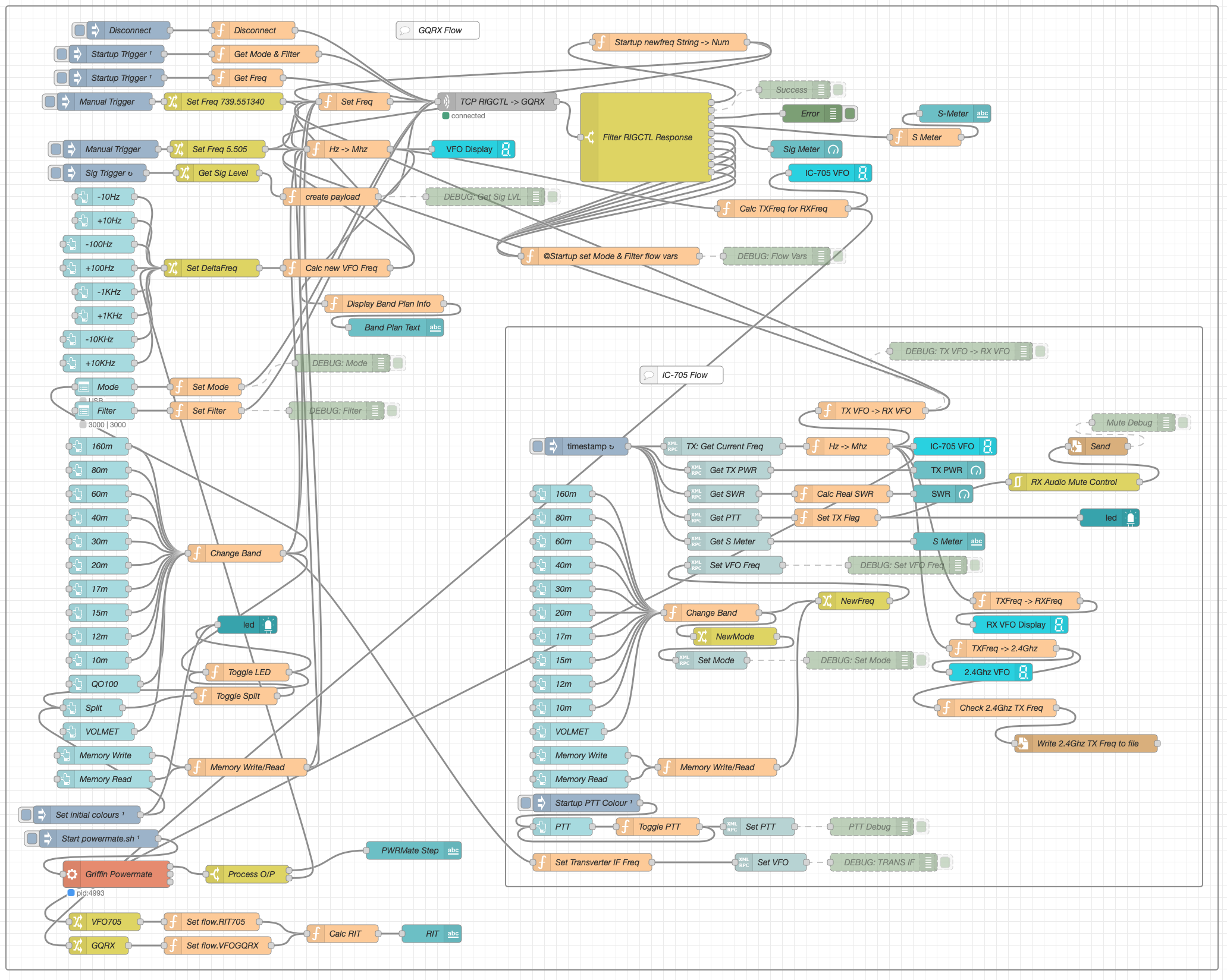
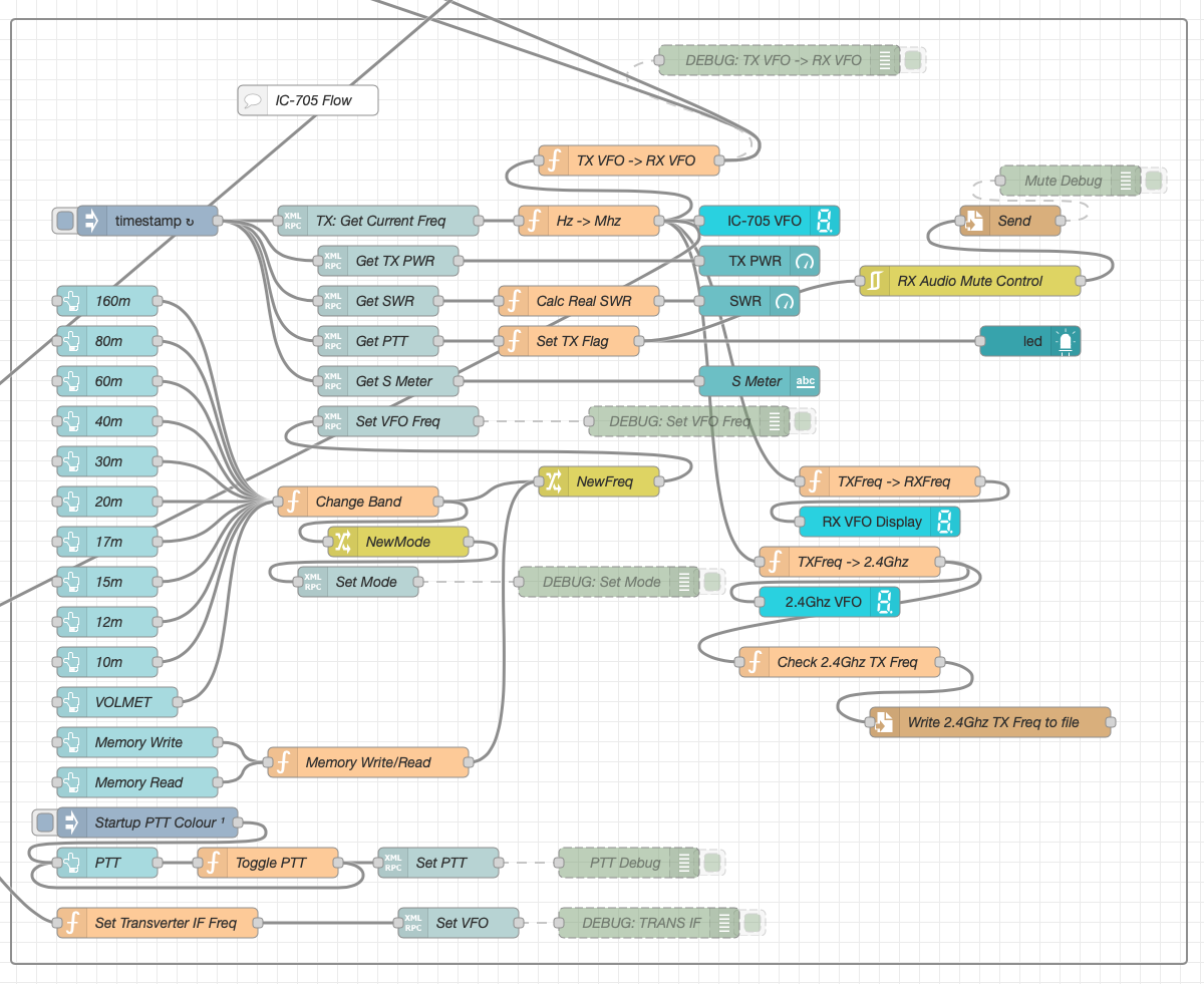
M0AWS Node-RED QO-100 Ground Station Dashboard Flow as of 12/06/24
The complete flow above looks rather daunting initially however, breaking it down into its constituent parts makes it much easier to understand.
There are two sections to the flow, the GQRX control which is the more complex of the two flows and the comparatively simple IC-705 section of the flow. These two flows could be broken down further into smaller flows and spread across multiple projects using inter-flow links however, I found it much easier from a debug point of view to have the entire flow in one Node-RED project.
Breaking down the flow further the GQRX startup section (shown below) establishes communication with the GQRX SDR software via TCP/IP and gets the initial mode and filter settings from the SDR software. This information is then used to populate the dashboard web app.
M0AWS Node-RED QO-100 Ground Station Dashboard – GQRX Startup Flow
The startup triggers fire just once at initial startup of Node-RED so it’s important that the SDR device is plugged into the PC at boot time.
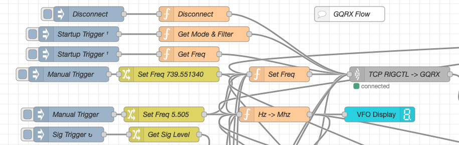
All the startup triggers feed information into the RIGCTL section of the GQRX flow. This section of the flow (shown below) passes all the commands onto the GQRX SDR software to control the SDR receiver.
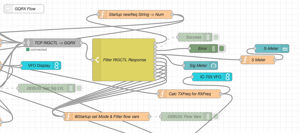
M0AWS Node-RED QO-100 Ground Station Dashboard – GQRX RIGCTL Flow
The TCP RIGCTL -> GQRX node is a standard TCP Request node that is configured to talk to the GQRX software on the defined IP Address and Port as configured in the GQRX setup. The output from this node then goes into the Filter RIGCTL Response node that processes the corresponding reply from GQRX for each message sent to it. Errors are trapped in the green Debug node and can be used for debugging.
The receive S Meter is also driven from the the output of the Filter RIGCTL Response node and passed onto the S Meter function for formatting before being passed through to the actual gauge on the dashboard.
Continuing down the left hand side of the flow we move into the section where all the GQRX controls are defined.
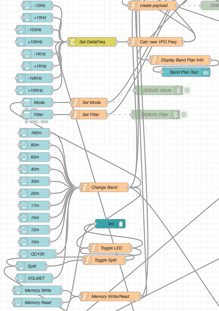
M0AWS Node-RED QO-100 Ground Station Dashboard – GQRX Controls Flow
In this section we have the VFO step buttons that move the VFO up/down in steps of 10Hz to 10Khz. Each button press generates a value that is passed onto the Set DeltaFreq change node and then on to the Calc new VFO Freq function. From here the new VFO frequency is stored and passed onto the communications channel to send the new VFO frequency to the GQRX software.
The Mode and Filter nodes are simple drop down menus with predefined values that are used to change the mode and receive filter width of the SDR receiver.
Below are the HAM band selector buttons, each of these will use a similar process as detailed above to change the VFO frequency to a preset value on each of the HAM HF Bands.
The QO-100 button puts the transmit and receive VFO’s into synchro-mode so that the receive VFO follows the transmit VFO. It also sets the correct frequency in the 739Mhz band for the downlink from the LNB in GQRX SDR software and sets the IC-705 to the correct frequency in the 2m VHF HAM band to drive the 2.4Ghz up-converter.
The Split button allows the receive VFO to be moved away from the transmit VFO for split operation when in QO-100 mode. This allows for the receive VFO to be moved away so that you can RIT into slightly off frequency stations or to work split when working DXpedition stations.
The bottom two Memory buttons allow you to store the current receive frequency into a memory for later recall.
At the top right of this section of the flow there is a Display Band Plan Info function, this displays the band plan information for the QO-100 satellite in a small display field on the Dashboard as you tune across the transponder. Currently it only displays information for the satellite, at some point in the future I will add the necessary code to display band plan information for the HF bands too.
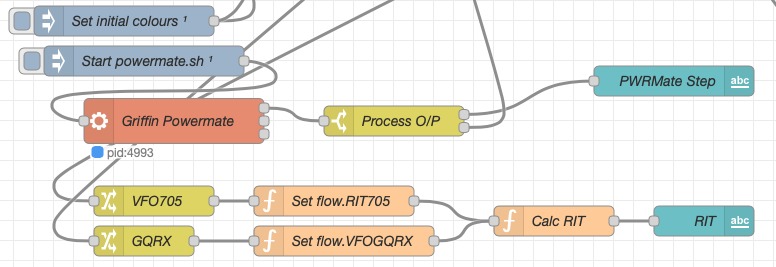
The final section of the GQRX flow (shown below) sets the initial button colours and starts the Powermate USB VFO knob flow. I’ve already written a detailed article on how this works here but, for completeness it is triggered a few seconds after startup (to allow the USB device to be found) and then starts the BASH script that is used to communicate with the USB device. The output of this is processed and passed back into the VFO control part of the flow so that the receive VFO can be manually altered when in split mode or in non-QO-100 mode.
M0AWS Node-RED QO-100 Ground Station Dashboard – Powermate VFO Flow
The bottom flows in the image above set some flow variables that are used throughout the flow and then calculates and sets the RIT value on the dashboard display.
The final section of the flow is the IC-705 control flow. This is a relatively simple flow that is used to both send and receive data to/from the IC-705, process it and pass it on to the other parts of the flow as required.
M0AWS Node-RED QO-100 Ground Station Dashboard – IC-705 Control Flow
The IC-705 flow is started via the timestamp trigger at the top left. This node is nothing more than a trigger that fires every 0.5 seconds so that the dashboard display is updated in near realtime. The flow is pretty self explanatory, in that it collects the current frequency, transmit power, SWR reading, PTT on/off status and S Meter reading each time it is triggered. This information is then processed and used to keep the dashboard display up to date and to provide VFO tracking information to the GQRX receive flow.
On the left are the buttons to change band on the IC-705 along with a button to tune to the VOLEMT on the 60m band. Once again there two memory buttons to save and recall the IC-705 VFO frequency.
The Startup PTT Colour trigger node sets the PTT button to green on startup. The PTT button changes to red during transmit and is controlled via the Toggle PTT function.
At the very bottom of the flow is the set transverter IF Freq function, this sets the IC-705 to a preselected frequency in the 2m HAM band when the dashboard is switched into QO-100 mode by pressing the QO-100 button.
On the right of the flow there is a standard file write node that writes the 2.4Ghz QO-100 uplink frequency each time it changes into a file that is used by my own logging software to add the uplink frequency into my log entries automatically. (Yes I wrote my own logging software!)
The RX Audio Mute Control filter node is used to reduce the receive volume during transmit when in QO-100 full duplex mode otherwise, the operator can get tongue tied hearing their own voice 250ms after they’ve spoken coming back from the satellite. This uses the pulse audio system found on the Linux platform. The audio is reduced to a level whereby it makes it much easier to talk but, you can still hear enough of your audio to ensure that you have a good, clean signal on the satellite.
As I said at the beginning of this article, this flow has grown organically over the last 12 months and has been a fun project to put together. I’ve had many people ask me how I have created the dashboard and whether they could do the same for their ground station. The simple answer is yes, you can use this flow with any kind of radio as long as it has the ability to be controlled via CAT/USB or TCP/IP using XMLRPC or RIGCTL.
To this end I include below an export of the complete flow that can be imported into your own Node-RED flow editor. You may need to make changes to it for it to work with your radio/SDR but, it shouldn’t take too much to complete. If like me you are using an IC-705 and any kind of SDR controlled by GQRX SDR software then it’s ready to go without any changes at all.
I get quite a few emails from readers of my blog asking how my QO-100 satellite station is put together and so, I thought perhaps now is a good time to put together an article detailing the complete build.
My QO-100 satellite ground station is built around my little Icom IC-705 QRP transceiver, it’s a great little rig and is ideal for the purpose of driving a 2.4Ghz transverter/up-converter.
Of course all the software used for the project is Opensource and freely available on the internet.
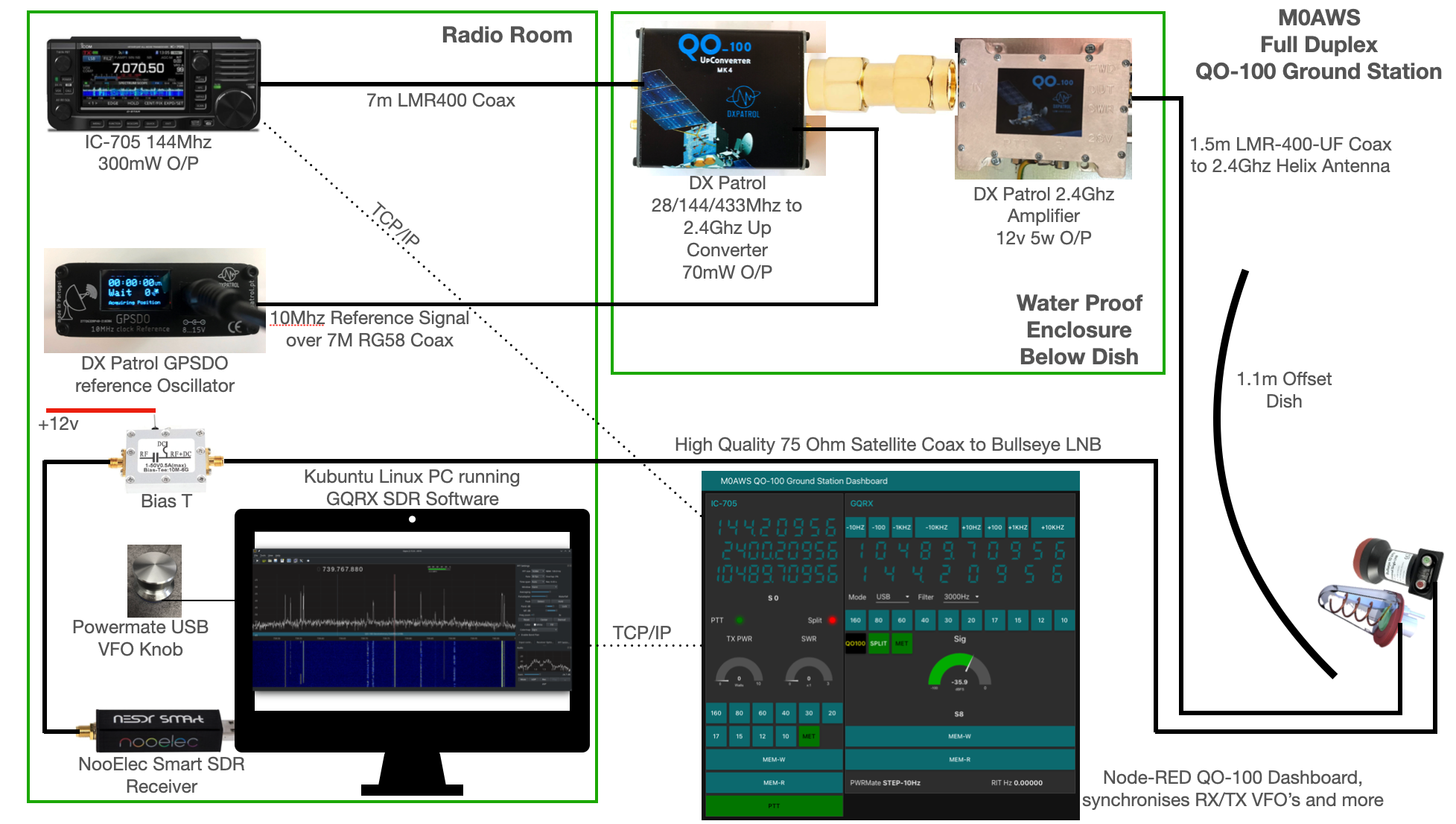
M0AWS QO-100 Ground Station Build Visual (Click to Enlarge)
The station comprises of the following building blocks:
QO-100 Ground Station Dashboard developed using Node-RED
LMR400-UF/RG58 Coax Cable
M0AWS QO-100 1.1m (110cm) off-set Dish with IceCone Helix antenna and Bullseye LNB.
To get a good clear view of the QO-100 satellite I have the dish mount 3.2m above the ground. This keeps it well clear of anyone walking past in the garden and beams the signal up at an angle of 26.2 degrees keeping well clear of neighbouring gardens.
The waterproof enclosure below the dish houses all the 2.4Ghz equipment so that the distance between the feed point and the amplifier are kept to a minimum.
The DXPatrol amplifier is spec’d to run at 28v/12w or 12v/5w, I found that running it at 28v produced too much output for the satellite and would cause the LEILA alarm on the satellite to trip constantly. Running the amp at 12v with a maximum of 5w output (average 2.5-3.5w) is more than enough for me to have a 5/9+10 signal on the transponder.
The large 1.1m dish gives me quite an advantage on receive enabling me to hear the very weak stations with ease compared to other stations.
2.4Ghz ground station enclosure ready for testing
The photo above shows the 2.4Ghz equipment mounted in the waterproof enclosure below the dish. This photo was taken during the initial build phase before I rewired it so, the amplifier is shown connected to the 28v feed. To rewire the amp to 12v was just a matter of removing the 28v converter and connecting the amp directly to the 12v feed instead. This reduced the output from a maximum of 12w down to a maximum of 5w giving a much better (considerate) level on the satellite.
It’s important to keep all interconnects as short as possible as at 2.4Ghz it is very easy to build up a lot of loss between devices.
For the connection from the IC-705 to the 2.4Ghz Up-Converter I used a 7m run of LMR-400 coax cable. The IC-705 is set to put out just 300mW on 144Mhz up to the 2.4Ghz converter and so it’s important to use a good quality coax cable.
Once again the output from the 2.4Ghz amplifier uses 1.5m of LMR-400-UF coax cable to feed up to the 2.2 turn Icecone Helix Antenna mounted on the dish. This keeps loss to a minimum and is well worth the investment.
Bullseye 10Khz High Stability Unversal Single LNB for 10.489-12.750Ghz
The receive path starts with a Bullseye LNB, this is a high gain LNB that is probably one of the best you could use for QO-100 operations. It’s fairly stable frequency wise but, does drift a little in the summer months with the high temperature changes but, overall it really is a very good LNB.
The 12v feed to the LNB is via the coax and is injected by the Bias-T device that is in the radio shack. This 12v feed powers the LNA and associated electronics in the LNB to provide a gain of 50-60dB.
Bias-T to inject 12v feed into the coax for the Bullseye LNB
From the Bias-T the coax comes down to the NooElec SmartSDR receiver. This is a really cheap SDR device (<£35 on Amazon) based on the RTL-SDR device but, it works incredibly well. I originally used a Funcube Dongle Pro+ for the receive side however, it really didn’t handle large signals very well and there was a lot of signal ghosting so, I swapped it out for the NooElec SDR and haven’t looked back since.
The NooElec SmartSDR is controlled via the excellent Opensource software GQRX SDR. I’ve been using GQRX SDR for some years now and it’s proven itself to be extremely stable and reliable with support for a good number of SDR devices.
To enhance the operation of the SDR device I have added a Griffin Powermate VFO knob to the build. This is an old USB device that I originally purchased to control my Flex3000 transceiver but, since I sold that many moons ago I decided to use it as a VFO knob in my QO-100 ground station. Details on how I got it working with the station are detailed in this blog article.
Having the need for full duplex operation on the satellite this complicates things when it comes to VFO tracking and general control of the two radios involved in the solution and so I set about creating a QO-100 Dashboard using the great Node-RED graphical programming environment to create a web app that simplifies the management of the entire setup.
M0AWS QO-100 ground Station Control Dashboard built using Node-RED.
The QO-100 Dashboard synchronises the transmit and receive VFO’s, enables split operation so that you can transmit and receive on different frequencies at the same time and a whole host of other things using very little code. Most of the functionality is created using standard Node-RED nodes. More info on Node-RED can be found on the Opensource.radio Wiki or from the menu’s above.
I’ll be publishing an article all about the QO-100 Dashboard in the very near future along with a downloadable flow file.
I’m extremely pleased with how well the ground station works and have had well in excess of 500 QSO’s on the QO-100 satellite over the last last year.
Thanks to Roy WN3F for alerting me to this. Tadashi-san has really built some beautiful stuff. Especially impressive to me is his use of the spectrum analyser and two-tone audio tests to look at IMD of the entire transceiver. See video above. FB OM.
We were in Korea for vacation, so naturally I wanted to do some SOTA. Korea is a mountainous place, and it looked like there were plenty of choices. The first summit we did is in the middle of Seoul, literally. The geographic center of the city is on the side of the plaza on top.
The tower is visible from a lot of places in the city, including this traffic island in Myeongdong.
Our hotel was in the Myeongdong neighborhood, near the Hoehyeon subway station. From exit 1, head uphill through the neighborhood. There was a flight of stairs just below a busy road, which we crossed to enter Baekboem Plaza. The tower on top was visible from here, and it was easy to follow the path to the bottom of the staircase.
From the plaza. Still some blossoms on the trees!
Since the summit is easy to get to in a big city, there were a lot of people out. The stairs up to the top were wide and paved. There are plenty of benches, and even a few viewing platforms on the way. It was hazy as we ascended, but we could still see Bukhansan a few kilometers away to the north. We were glad it was cool out, it probably would have been a miserable hike in the summer.
Base of the stairs.
You know you are close when you see the cable car terminal. This is also where it goes from busy to crowded. Once you make it up the last few stairs, there are plenty of benches around the plaza and under the structure. We sat for a few minutes taking in the scene. On one side the fence is filled with locks that couples have attached. There was even a vending machine to buy your own to add.
High point of Namsan.
We found a bench out of the way, and I got on 2m. I had been warned that Korean hams are chatty, and they were. It took a couple of minutes calling CQ, but I soon had a long conversation with someone who couldn't quite get my Korean callsign (HL1/AA6XA). The slash seemed to trip him up. After a long chat I got two more stations in the log. Some more CQ calls didn't get anyone else, and we were getting bored and hungry, so I packed up. I thought about trying HF, but there really isn't anywhere to put up a wire without getting in people's way.
At the geographic center of Seoul.
We took the stairs back down, then turned onto a different road to get to the bibimbap restaurant near the base. It was a tasty and well earned lunch.
Trailhead: We started from Hoehyeon Station exit 1, but there are myriad routes one could take
In a previous post, I looked at the Low Interference Potential Devices (LIPD) Class Licence in Australia and how it allowed individuals to transmit with very low power in parts of the low-band VHF spectrum.
Tony Mann is a radio experimenter in Perth, Western Australia and has over the last 12-months been operating four beacons in the low-VHF bands with each one running 100 milliwatts.
The frequencies were 30.8761 MHz , 36.6073 MHz, 39.1467 MHz and 40.6864 MHz.
In 2023, several stations heard the beacons and there are shown on the map above.
Short wave listener Hugh Cocks (HC02) is in the south of Portugal. Phil, EI9KP is located in the west of Ireland. Paul, G7PUV is located in the SE of England. All three are in the region of 15,000 kms.
Otto, VK4OTZ in Queensland, Australia is about 3,700kms to the east which is pretty much ideal for one F2 layer hop.
Tony informs me that he initially made a single frequency “beacon” on 36.860 MHz for the southern hemisphere F2 season in March-May 2023. It was simple crystal oscillator modulated by a PIN diode.
By July 2023, he had a second beacon on 30.876 MHz which was still heard in Sydney via F2 up until September 2023. By that time, Hugh Cocks in Portugal was interested in trying, so he ran 30 MHz after late Sept 2023, quickly added 36 MHz, then 39 MHz by 10 Oct and finally by 29 Oct had a 4th, 40 MHz beacon running.
The 36.860 MHz frequency was changed to 36.607 to avoid DX radar interference in Europe. The 40 MHz beacon was never received as by mid-Nov 2023 conditions had deteriorated.
Tony's antenna is shown below...
Tony uses two vertical dipoles: On the left is a single dipole for 30.9 MHz and on the right is a folded dipole for 36-41 MHz (which works adequately on 30.9 MHz).
The beacon signal is alternately switched on for 0.5 seconds, then off for 1.5 seconds. The cycle repeats every two seconds. There is a 0.5 second gap where no power is going out.
The screen grab above from Hugh, HC02 in Portugal shows what the 39.1467 MHz signal looked like on the 11th of March 2024.
Videos... This clip from Paul, G7PUV shows reception of the 30.876 MHz signal...
The video clip below shows reception of the 36.860 MHz signal by VK4ATZ...
Current Status - March 2024: Tony is currently carrying out propagation tests as we're close to the equinox.
Tony writes... "I am ready to resume the 07-11 UTC tests for Europe in March 2024 and I anticipate adding 00-04 UTC for the autumn F2 season in Australia."
It would be interesting to see more reports of people hearing Tony Mann's beacons. Perth to North America? Perth to South America?
If you hear anything then you can leave a comment here.
Like many amateur operators, I have far too many handie talkies (HTs). I’ve cycled through many, and sold or given away many that I was done with. Some of those I wish I hadn’t sold (like the Kenwood TH-D74), but others I was glad to be rid of. I thought I would take a few paragraphs to talk about what I use day to day, and what I like and don’t like about these radios. I should note that I won’t discuss the HTs that I use in wildland fire communications as that is an entirely different purpose and topic.
On a regular basis and in addition to analog FM, I use DMR and Yaesu C4FM. To a lesser extent, I use P25 on amateur networks. Rarely do I ever use D-STAR any more, and then only via DVswitch and the mobile app on the phone.
I like using DMR. I’ve always liked the networks (specifically Brandmeister) and the architecture. I know, the digital audio is totally different than the richness of analog, but it’s still fun. And DMR was where I really learned about bridging and how I got into XLX reflectors.
For DMR, I mainly use the Anytone 878UV Plus II. I also use a Radioddity GD77 with the OpenGD77 firmware, and a Motorola XPR7550e. Of these three, I think the 878 is probably the best everyday choice. Yes, the 878 has its weird quirks, and the CPS (Customer Programming Software) is pretty bad, but the radio is fairly solid and easy to operate. And it sounds very good, both on receive and transmit. I also like the form factor and feel in the hand when operating. The OpenGD77 firmware is probably the most ham-friendly DMR firmware in existence, and is a pleasure to operate. But the hardware (Radioddity GD77) isn’t nearly as nice as the Anytone. I do like this radio as well, and keep one in the shed and use it while I’m out working in the yard. These radios as so inexpensive that you can have a couple and not worry about beating them up. In addition, both the 878 and the GD77 work very well with the Mobilinkd TNC4 for packet.
I don’t use the Motorola XPR7550e as much. It is a good solid radio, but is lacking a lot of the ham friendly features (like direct TG entry and persistence). I use it mostly on the Rocky Mountain Ham Radio region-wide DMR network where I am usually parked on one repeater/TG (Talkgroup) or roaming on a single TG.
For Yaesu C4FM (commonly referred to as “Fusion”), I use the FT-5DR. I also have an older FT-2DR, but it is relegated to my PDN (Personal Digital Node). The FT-5DR is a decent radio, and has a lot of APRS features. But to me, it feels pretty cheap. Indeed, mine has develoepd the dreaded case crack (or “mold line” as Yaesu likes to call it). It also goes through batteries very quickly. I always carry 2 extra batteries for this radio. I think my main gripes about this radio are the audio quality and the form factor. It does not sound very good, probably owing to the tiny size and small speaker. And it feels uncomfortable to hold an operate. I mostly use Yaesu C4FM because it is becoming more and more popular in our area, but I will admit that I am a bit of a reluctant user.
In my opinion, the Kenwood TH-D74 was the best APRS HT that I have ever owned. I should not have sold that. Kenwood’s APRS implementation and UI are much better than Yaesu’s, and the receiver in the Kenwood radios is much, much better than the Yaesu. I just wish Kenwood hadn’t gone with D-STAR as their digital mode of choice.
Finally, I use P25 a bit over a hotspot on amateur radio. For that I use a UHF Motorola XTS2500. I said I wouldn’t talk about wildland fire radios in this post, but I did it anyway. I also use this radio on fires, as it is one of the NIFC (National Interagency Fire Center) approved radios. This is a very solid older radio with great audio. The CPS is a real bear to deal with (read: it is horrible and not ham friendly), but the radio is awesome. On fires, I use it with a very large AA batttery clamshell that holds 12 batteries, but around the house I use an old rechargeable battery.
Anyway, as you can see I like HTs Maybe in a future post I will discuss some others, and talk about what we use in wildland fire.
I’ve been on the QO-100 satellite for about 7 months now and I have to admit I love it!
Having a “Repeater In The Sky” that covers a third of the world really is a wonderful facility to have access to however, there is one thing that I find tiring and that is the high level of background noise that is always present.
Even though the signals are mostly 59-59+15dB the background “hiss” is very pronounced and gets very tiring after a while, especially if like me you have tinnitus.
Currently I’m using a NooElec Smart SDR for the receiver and GQRX SDR software on my Kubuntu Linux PC. This works great but, there is one short fall, there is no DSP Noise Reduction (NR) in the software or hardware.
To fix this I recently invested in a BHI Dual In-Line Noise Eliminating Module. The unit itself is nicely put together and has a good combination of inputs and outputs making it easy to connect up to my MacBook Pro to record QSOs and connect my headphones at the same time.
M0AWS BHI Dual In-Line Noise Eliminating Module
At £189.95 plus postage from BHI direct it’s not cheap but, it is nicely put together and comes complete with a power lead and a couple of cheap audio cables. The quality of the knobs and mechanisms is good apart from the little grey DSP Filter Level knob that feels cheap and is very wobbly on the switch below. I’m not sure how long this is going to last with prolonged use and will most likely need replacing with something a little sturdier at some point in the future.
Overall noise reduction is good but, the audio amplifiers on the Audio Input Level and Line Out Level distort very early on in their range and you cannot get them much above level 5 before distortion starts to appear on the received signal. This is disappointing as my headphones are of reasonable quality and are let down by the distortion creeping in from the audio amplifier in the BHI unit.
I’ve tried altering the levels on the input from the IC-705 and no matter what I cannot get a good audio signal in my headphones without some distortion on the higher frequency ranges.
Overall the device does do what I want, it reduces the background “hash” considerably reducing the fatigue whilst chatting on the satellite. Below is a recording from a conversation on the satellite showing the noise reduction performance of the BHI module.
M0AWS Example BHI DSP NR Recording
The recording starts with the BHI DSP NR off, at 00:07 the DSP NR is switched on, you can clearly hear the difference. At 00:23 the DSP NR is turned off again and at 00:36 the DSP NR is turned on again. The BHI DSP NR Module is set with the DSP Filter Level set at 3 out of 8 which appears to be the best level to use. Switching to level 4 starts to introduce digital artefacts to the audio which only gets worse the higher the DSP Filter Level goes.
With a setting above level 3 there really isn’t much improvement in noise reduction and the audio becomes progressively more affected by the digital artefacts than it does from the background noise.
M0AWS BHI Dual In-Line Noise Eliminating Module with Icom IC-705 QO-100 Ground Station
The only other problem I have with the BHI Dual In-Line Noise Eliminating Module is that is comes in a plastic case. The case itself is solid and of good quality however, it offers no RF shielding whatsoever and the unit is extremely susceptible to RF getting into the audio chain and then being heard during transmit in the headphones and via the line out connections. For the money I would had expected the unit to come in a metal case that provides proper RF shielding. This is a real shame as it lets the unit down considerably.
As setup in the photo above I am using 300mW O/P on 144Mhz from the IC-705 into a perfect 1:1 SWR presented by the DX Patrol 2.4Ghz Upconverter via some very high quality LMR-400 Coaxial cable from Barenco but, I get terrible RF interference via the BHI unit during the transmit cycle. Considering I am only using 300mW I dread to think what it may be like if I was using a 100w HF radio. This is something I need to investigate further as it really is very annoying.
Moving the unit to a different location in the radio room does help a bit but, doesn’t solve the problem completely. At 300mW RF O/P I really didn’t expect there to be a problem with RF getting into the BHI unit.
Having a proper line-out facility on the BHI unit really is nice as it makes it very easy to connect to my MacBook Pro to obtain good quality recordings of signals on the QO-100 satellite as can be listened to above.
Overall I am happy with the BHI Dual In-Line Noise Eliminating Module but, do wish that more care had been taken over using a metal case instead of a plastic case to protect the unit from RF ingress and better audio amplifiers within the unit that don’t distort/clip so early on in their O/P levels.
Is this the perfect noise reduction unit?
No but, overall it is better than nothing and does help to reduce the background noise to a more acceptable level reducing the overall fatigue during prolonged conversations on the QO-100 satellite.
UPDATE: I tried the BHI unit with my FTDX10 on the HF bands and the RF interference is horrendous, even when using QRP power levels! This device clearly hasn’t been designed to work in an RF environment and the total lack of shielding or isolation lets it down terribly. If you are an SWL then this unit is fine but, if like me you like to monitor your transmitted audio whilst on air through headphones then this isn’t the unit for you. To prove the problem isn’t in the radio shack I put the BHI unit in the house some 30m away powered by 12v battery with nothing connected but a pair of headphones and still the unit suffered from RF interference even at QRP levels.
A lot of countries allow the use of low power transmitters at certain frequencies without the need of a licence. In this post, we'll look at the low VHF frequencies available in Australia with the LIPD (Low Interference Potential Devices) Class Licence.
Why Low VHF? With the annual Summer Sporadic-E season and at the peak of the 11-year sunspot cycle, these very low power transmitters have the potential to be heard over many thousands of kilometres.
Frequency Range - Width of band - Maximum Power - My notes
29.700 to 29.720 MHz - 20 kHz - 100mW or -10dBW EIRP* - This starts just above the 10m amateur radio band
30.000 to 30.0625 MHz - 62.5 kHz - 100mW or -10dBW EIRP* -
30.3125 to 31.000 MHz - 687.5 kHz - 100mW or -10dBW EIRP* -
36.600 to 37.000 MHz - 400 kHz - 100mW or -10dBW EIRP* -
39.000 to 39.7625 MHz - 762.5 kHz - 100mW or -10dBW EIRP* -
40.250 to 40.660 MHz - 410 kHz - 100mW or -10dBW EIRP* -
40.660 to 41.000 MHz - 340 kHz - 1W or 0dBW EIRP* - 1) Note the higher power 2) This overlaps with the ISM (Industrial, Scientific, Medical) band of 40.660 to 40.700 MHz which is implemented in most countries.
54.000 to 56.000 MHz - 2 MHz - 2.5mW or -26dBW EIRP* -
70.000 to 70.24375 MHz - 243.75 kHz - 100mW or -10dBW EIRP* - Note that this overlaps with the 4m amateur radio band
77.29375 to 77.49375 MHz - 20 kHz - 100mW or -10dBW EIRP* -
*EIRP - EIRP means equivalent isotropically radiated power. This is the radiated power from a theoretical point source with the radiation pattern shown as a sphere.
A worked example might be as follows...
Example 1: The antenna is a half-wave dipole with a gain of about 2.1dBi. The coax loss is 1dB. The radio transmitter would need to be limited to about 750 milliwatts to comply with the 1-watt EIRP limit. If the limit is 100-milliwatts then the power should be kept at 75-milliwatts.
Example 2: If a long length of coax was used to feed the antenna and the loss was 2.1dB. This would cancel out the antenna gain and the transmitter can be used at 1-watt or 100 milliwatts depending on the frequency.
Restrictions: Other than the EIRP, there are a few restrictions such as avoiding radio astronomy sites. The licence clause also states... "The transmitter, whether on its own or in operation with one or more other transmitters, must not cause interference to the operation of radiocommunications services" and "A receiver tuned to the transmitter will not be afforded protection from interference caused by other radiocommunications devices."
Experiments: In January of 2023, I had a post up about how radio experimenters were using very low power transmitters on the 40 MHz band and how a 5-milliwatt transmitter reached almost 6000kms. See post HERE
Phil, EI9KP is located in the north-west of Ireland and he carried out a propagation experiment on 32.013 MHz on Saturday 27th January 2024 from 09:00 to 17:00 UTC. He was running 5-watts into a vertical dipole and used FT8 and CW to ID.
And yes, before anyone asks, that's not a mistake. Radio amateurs in Ireland have permission to use 32 MHz.
Report from Phil, EI9KP... "I had my Low VHF antennas bent and broken in storm 'Isha' and am in the process of rebuilding. A few days ago I resurrected my Low VHF Test Dipole. Since there are now no coupled dipoles the test dipole was resonant on 31.600MHz. I measured an SWR of 1.5 on 32.013MHz, it looked like a good opportunity to reconnect the beacon for a day.
I have received the following reception reports (PSKReporter, email, EI7GL blog):"
Europe... These are the stations in Europe that heard the signal...
Gintas, LY2YR in Lithuania (KO24OS) at 2188kms was probably F2 layer
Ari, OH5FI/OH5KUY in Finland (KP41DB) logged several FT8 signals and gave this report...
Fine copy at KP41db. Max: 240127_105300 22 -0.5 243 DE EI9KP IO54. Min: 240127_142815 -14 -0.3 242 DE EI9KP IO54 73 / OH5KUY
At 2316kms, the propagation mode was likely F2 again.
Costas, SV1XV in Athens, Greece (KM18UA) at 3045kms reports the following... "I can also receive EI9KP beacon on 32013.0 kHz CW, RST 559, giving loc IO54MB. Time 15:18 UTC, loc KM18." and " I can receive EI9KP beacon on 32013.2 kHz FT8, peaking at -11 dB. Time 15:10 UTC, loc KM18."
Alex, SV8QG in Greece (KM39GC) at 3133kms logged some FT8 signals from 10:52-11:01 UTC. Alex sent on the following decodes...
QRG 32,O12 USB REC IC-7200 ANT 4L@10m QTH KM39GC
105215 -2 -0.3 1201 ~ DE EI9KP IO54 105300 1 -0.5 1200 ~ DE EI9KP IO54 105315 -7 -0.3 1201 ~ DE EI9KP IO54 105400 -1 -0.5 1200 ~ DE EI9KP IO54 105415 -3 -0.4 1200 ~ DE EI9KP IO54 105500 -2 -0.5 1201 ~ DE EI9KP IO54 105515 -7 -0.4 1200 ~ DE EI9KP IO54 105600 -1 -0.5 1200 ~ DE EI9KP IO54 105615 4 -0.4 1201 ~ DE EI9KP IO54 105700 3 -0.5 1200 ~ DE EI9KP IO54 105715 5 -0.4 1200 ~ DE EI9KP IO54 105800 -7 -0.5 1200 ~ DE EI9KP IO54 105815 -8 -0.3 1201 ~ DE EI9KP IO54 105900 -1 -0.5 1200 ~ DE EI9KP IO54 105915 4 -0.4 1200 ~ DE EI9KP IO54 110000 -1 -0.5 1200 ~ DE EI9KP IO54 110015 -9 -0.4 1200 ~ DE EI9KP IO54 110100 -4 -0.5 1200 ~ DE EI9KP IO54 110115 5 -0.4 1200 ~ DE EI9KP IO54
Phil, EI9KP continues... "The morning signals received in OH were extremely strong e.g. +22dB SNR, as was the report from Greece."
The signals to Greece at about 3000kms were almost F2 layer as well. As we look at western Europe, we move into the F2 skip zone.
Hugh, HC02 is a short wave listener in the south of Portugal in IM67BB (1892kms). Hugh writes... "Receiving the beacon - 16 to - 18dB in Portugal IM67 from an easterly direction at 0920 so must be backscatter."
EI9KP writes.. "Many thanks to Hugh for an all day reception report which I have represented in a graph above. Scatter throughout the day with signals -15/-20 dB SNR with a 10 minute peak at around 12:28 UTC."
Paul, G7PUV / G9PUV in the south-east of England (JO00AU - 706kms) writes... "Two decodes here, both likely to be backscatter while I was beaming East.
----- 27.01.24 10:32:30 UTC ---------------
103215 -20 0.4 1140 ~ DE EI9KP IO54
----- 27.01.24 10:45:29 UTC ---------------
104515 -19 0.4 1140 ~ DE EI9KP IO54 "
EI7GL... This is my own report. I used an old HF radio tuned to 32.0124 MHz on USB with a vertical half-wave for 28 MHz. The distance from EI9KP to my location on the south coast of Ireland is 248kms.
The signal was very weak and the screenshot above is going from right to left.
At the bottom around 600 Hz, you can see the trace from the CW signal. I couldn't actually hear this by ear but I could see it on screen for most of the time. I didn't get that many FT8 decodes but the weak FT8 signal can be seen above around 800 Hz.
These are my FT8 decodes from the 8-hour period that I was monitoring the frequency...
090915 -20 -1.7 804 ~ DE EI9KP IO54
131115 -18 -2.1 813 ~ DE EI9KP IO54
133515 -20 -2.1 814 ~ DE EI9KP IO54
140615 -19 -2.2 815 ~ DE EI9KP IO54
161000 -20 -2.6 818 ~ DE EI9KP IO54
161100 -19 -2.6 818 ~ DE EI9KP IO54
165315 -18 -2.5 819 ~ DE EI9KP IO54
165515 -18 -2.5 819 ~ DE EI9KP IO54
165615 -18 -2.5 819 ~ DE EI9KP IO54
165715 -16 -2.5 819 ~ DE EI9KP IO54
165815 -15 -2.5 819 ~ DE EI9KP IO54
165915 -14 -2.5 819 ~ DE EI9KP IO54
170015 -16 -2.5 819 ~ DE EI9KP IO54
170115 -16 -2.5 819 ~ DE EI9KP IO54
170215 -16 -2.5 819 ~ DE EI9KP IO54
170315 -15 -2.5 819 ~ DE EI9KP IO54
170415 -15 -2.6 819 ~ DE EI9KP IO54
170515 -16 -2.6 819 ~ DE EI9KP IO54
170615 -16 -2.6 819 ~ DE EI9KP IO54
As for the propagation mode? At 248kms, it's hard to say. I'm close enough that the signal may have been direct but F2 backscatter can't be ruled out. I'd need to do the test at night to be sure if it was direct or not.
Whatever the propagation mode, I came to the conclusion that I'd need about a 10dB improvement in the signal for me to hear it properly.
North America... These are the reports from the USA and Canada...
Bernard, VA2CY in Quebec, Canada (FN46LW - 4321kms) reported reception at 13:57, 15:01 and 17:02 UTC. EI9KP writes... "Bernard VA2CY is using a 80-meter dipole oriented SW-NE. On 32 MHz this makes an antenna pattern having lobes off the ends."
Andrew, K8EL in Ohio (EN91EB - 5383kms) sends on the following screenshot...
Larry, VO1FOG in Newfoundland, Canada (GN37IN - 3146 kms) reports that the beacon was in from 1230 till switch-off at 1707 UTC.
EI9KP concludes... "It is worth noting that stations VA2CY and K8EL and on the same line viewed from IO54MB. Last reception reports from Europe were at 1520 (Greece) and 1707 (Canada)."
In conclusion... It's nice to see that one experimental transmission on an odd frequency in the low-band VHF region generated so much interest. It's unlikely we'll see any amateur radio activity from other countries at 32 MHz but that doesn't mean people can't experiment and try to listen.
No doubt Phil will be carrying out more experiments on 32 MHz in the future and we'll try and get the word out a few days earlier for the next one.
Link... I have the results of some previous 34 MHz propagation tests up on my 40 MHz page.
This is not the most interesting summit I've done. It is, however, a short and easy hike. Drive up to the end of Lakeside Drive, and find a place to park in the neighborhood. At the end of the pavement, the dirt starts and it is a quarter mile up to the summit.
The summit is visible from the trailhead.
You can see where you want to go, so just walk on up. The eroded jeep trails are an easy walk, but would require some serios OHV capability to drive. The top is rocky, but it wouldn't be too hard to set up an HF antenna. I was short on time, so I did VHF only. It took about 15 minutes to get four contacts, and I was worried I'd have to leave before I got number four.
Views of the Jurupa Hills, and the San Gabriel Mountains.
Talking with locals later, it sounds like that area is just not very good for VHF. Too low and far away from the chasers in LA, and not that many hams in the inland empire. Oh well, next time I'll leave more time for HF.
Back at the car it was a short drive over to the airport for my flight home.
This mountain west of Portland is an easy activation. There are a few places you can activate from. The traditional spot is at the Winkelman dog park on SW175th Ave in Beaverton. But the Cooper Mountain Nature Park on SW Kemmer Road is also in the activation zone, and this is where I chose to set up. See the video linked at the bottom for a longer exploration of the actual activation zone.
Not the greatest view, but at least I was in the shade.
There was plenty of parking on the Thursday afternoon I stopped by. There wasn't much shade in the parking lot, though, so I walked a few meters down the trail to a picnic table under a tree. I wasn't in the mood for setting up HF, so I only brought my HT and did 2m. The hill is in the middle of the Portland metro area, so there were plenty of chasers. Most people were on 58, but I did get one random person on 52. There was a bit of interference from something, so I was glad to have the band pass filter with me.
Getting those QSOs.
After I had made half a dozen contacts, N7KOM took his dog up to the park, and I drove over to have an eyeball QSO. It is always nice to meet SOTA people from other areas. It was hot, and I was getting tired, so after talking a while I headed back to the city.
Trailhead: Winkelman Park or Cooper Mountain Nature Park
Route: Both parking lots are in the AZ, so find somewhere comfortable to set up.
Red Tape: Dogs are not welcome at the nature park, and I wonder if they really want people stringing wire antennas around there. I had no issues doing VHF only.
Since purchasing my Retevis RT85 2m/70cm handheld radio I’ve noticed that it seems rather deaf when using the antenna that came with the radio and isn’t as strong into the local repeaters as I imagined it would be.
Considering the local 2m and 70cm repeater isn’t that far from my QTH and there is pretty much a clear line of site view in the direction of the repeater I was somewhat surprised that on 70cm the repeater never breaks the squelch, even if it is set on it’s lowest setting of zero.
M0AWS Retevis RT85 dual band VHF/UHF Handheld Radio
Connecting my home made end fed dual band vertical dipole at 10m above ground the performance of the radio improves drastically as one would expect.
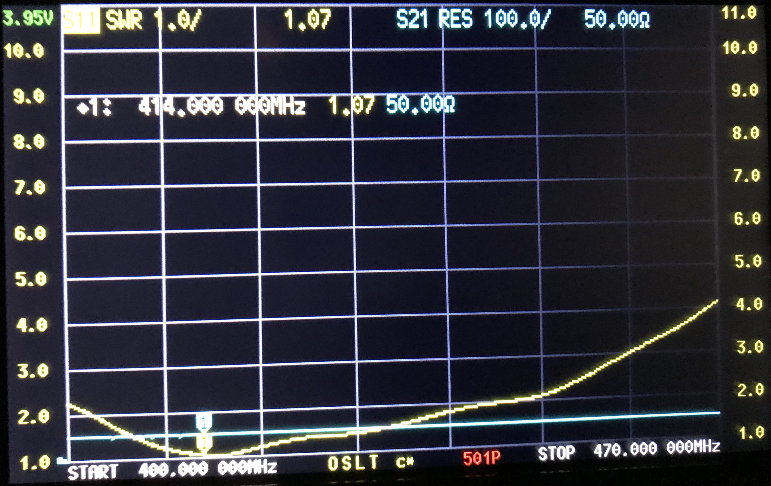
Having recently purchased a JNCRadio VNA 3G antenna analyser I decided to connect the Retevis supplied antenna to the analyser and see what the resonance was like on the two bands.
The antenna is labelled as 136-174Mhz and 400-470Mhz. This is an extremely wide frequency range for such a small antenna and clearly isn’t going to perform that well over such a wide bandwidth.
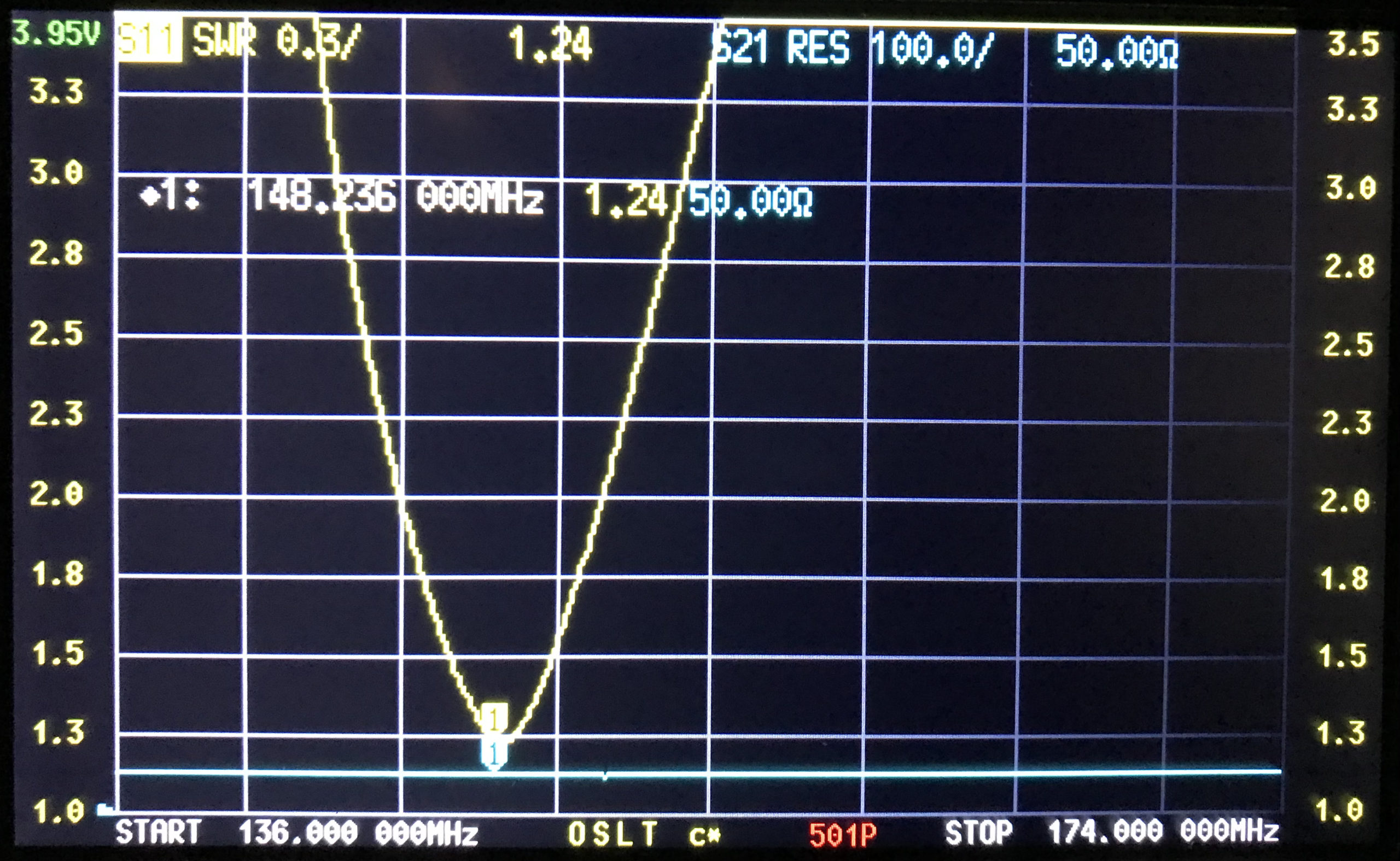
Connecting the antenna to the VNA and setting the stimulus frequency range to 144-148Mhz I found that the SWR curve of the antenna wasn’t particularly good.
M0AWS Retevis RT85 Antenna SWR Curve 2m
As shown above the SWR curve on the 2m Band is pretty poor. At 144.0Mhz it’s just over 3:1, at 145.496 (closest I could get to the 145.500 calling channel) the SWR is still 2.1:1. The antenna doesn’t really get close to resonance until 148Mhz where the SWR is 1.46:1.
With an SWR this high the radio will almost certainly be reducing the O/P power considerably to protect the PA stage from over heating due to so much power be reflected back into the transmitter. This explains the poor performance when using 2m repeaters locally and the somewhat limited range when using the OEM supplied antenna.
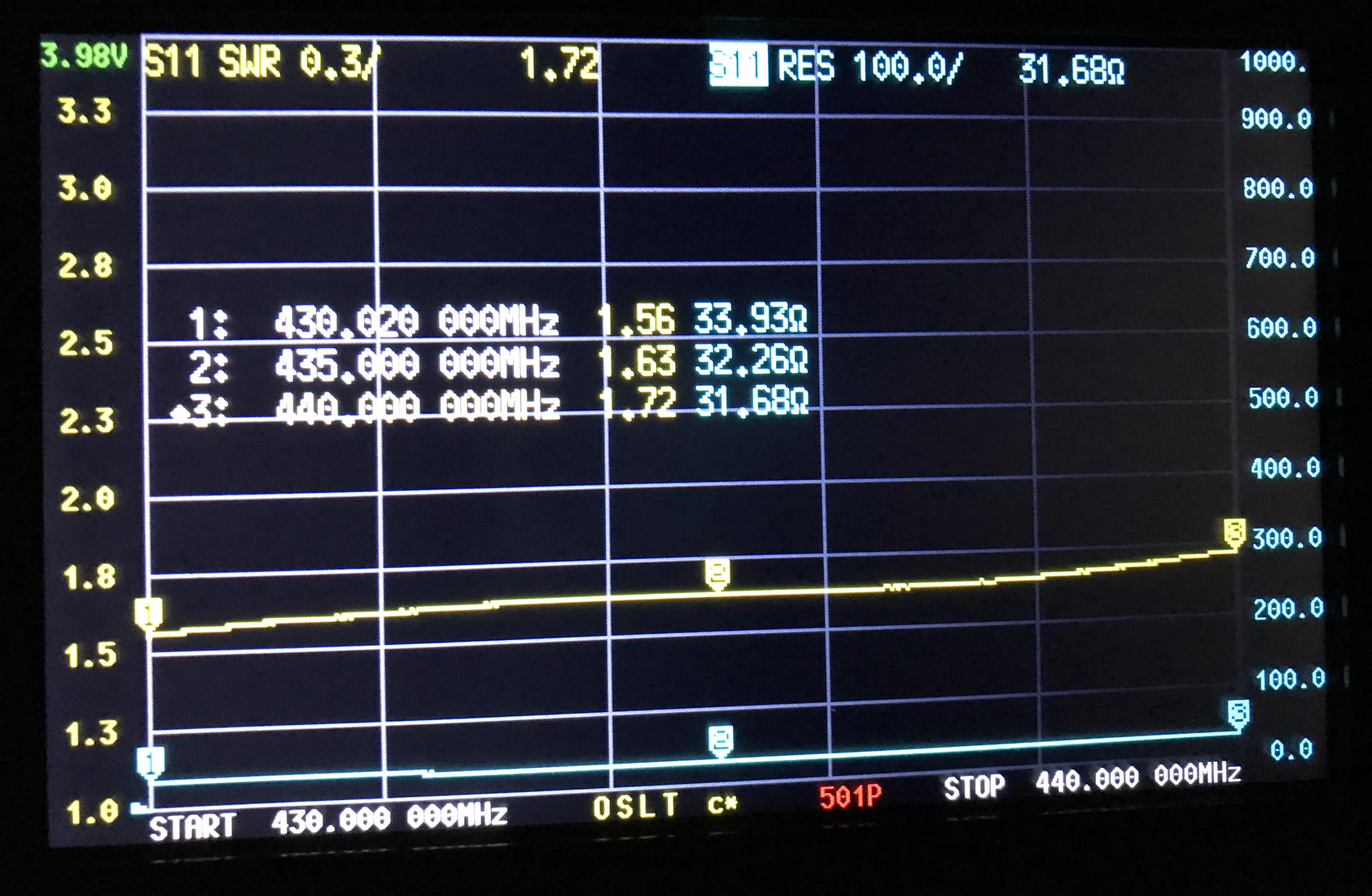
Looking at the SWR curve on the 70cm band, the antenna is much closer to resonance than it is on the 2m band but, it’s still not perfect.
M0AWS Retevis RT85 Antenna SWR Curve 70cm
At 430Mhz the SWR is 1.56:1, at 435Mhz 1.63:1 and 440Mhz 1.72:1. Since the antenna is much closer to resonance on the 70cm band I would expect it to perform better than it does.
Looking at the SWR curves over the entire supported frequency range of 136-174Mhz and 400-470Mhz, there is only one point of resonance on VHF around 148Mhz and on UHF around 400Mhz.
With such disappointing performance on both VHF and UHF I’ve decided to investigate making my own 2m/70cm antenna for the handheld to see if I can improve both the SWR on each band and the overall performance of the radio.
Much has been said about the electrical disadvantages of using a magnetic mount for your VHF/UHF mobile needs. Measurements compare the magmount to a thru-hole NMO mount.
Some time recently Pleasanton Ridge regional park was expanded to include the southern part of Sunol Ridge. This is great news for peak baggers and SOTA enthusiasts - there is now a public trail to the summit. The trailhead is the Tyler Ranch Staging Area at the end of Foothill Road in Sunol. There is a large dirt lot with pit toilets.
Looking down at the new parking lot.
There are two trails that head up from here. The shorter paved road, or the dirt trail that rejoins the road at the end of the pavement via a long switchback. I took the switchback up and the road down for some variety. The main trail that runs up and along the ridge is called the Sunol Ridge Trail. Stay on this, and you'll be taken directly to the summit.
Partway up the steep section.
The forecast was not great for the Friday I went, but I decided to risk it. It was pretty nice below the clouds, but as I climbed it got colder and windier. Around the base of the clouds it even rained a little. There were no views, sadly. Just before the summit I scared some cows out of the way, then reached the paved road that comes up from the west. I took this the last quarter mile or so to the top.
View as I approached the summit.
It was cold and windy, so I walked around the fence surrounding the many towers to try and find somewhere out of the wind. I partially succeeded, but it was a cold activation. There was some sort of HF blackout that morning, and I barely made three contacts on 20-30-40. Luckily I had thrown in my HT just before leaving, so I was able to get enough contacts for the point.
Looking over at Pleasanton Ridge on the way down.
The clouds had lifted some while I was on the summit, so I had some ok views on the way down. The high peaks were still obscured, but I enjoyed what I could see. I also was moving pretty quick, since I was cold after sitting for so long. The hike down was quick, and a real leg workout. Overall, it was a good hike, and I'm glad this new area has been opened.
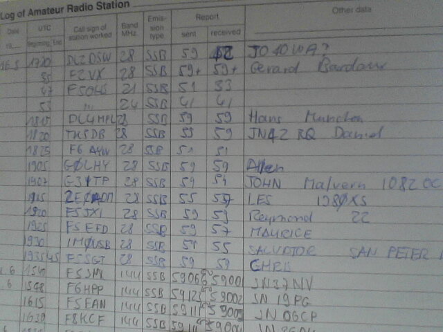
Fast Log Entry est un logiciel qui permet de saisir rapidement et plus simplement un carnet de trafic papier dans votre programme de log habituel.
Il y a deux exemples d’application de ce logiciel: Vous avez noté les dizaines de QSO lors d’une sortie en portable sur un bout de papier et vous voulez ensuite les saisir dans votre programme de log. Ou alors, vous avez des anciens logs papier vieux de plus de 20 ans et vous voulez les entrer dans votre programme de log habituel pour ensuite gérer ces QSO pour obtenir différents diplômes. Dans ces 2 cas, les entrer directement dans votre programme de log est long et fastidieux.
DF3CB a bien compris le problème et a trouvé une solution par un petit logiciel qui permet de transformer les informations minimales saisies dans un fichier texte, évitant ainsi devoir se déplacer dans les différents champs de votre programme de log, supprimer toutes les informations redondantes et les transformer dans un format reconnu. Cela fait gagner un temps considérable qui peut être à mettre pour des choses plus intéressantes comme faire des QSO supplémentaires
Comment ça marche ?
Le plus simple est de regarder la vidéo de Tim N7KOM.
Une fois les données entrées dans le fichier texte, c’est là que le petit logiciel FLEcli entre en jeux. Il va permettre de transformer votre fichier texte minimal dans de différents formats comme adif qui permettra ensuite d’importer les QSO dans votre programme de log habituel ou en csv pour valider les QSO SOTA comme le montre Tim dans sa vidéo.