A great add on to the MPAS kit or just as a stand alone.
I do find the counterpoise wires o be too thin and prone to breakage and want Chameleon to go back to the #16 Kevlar wire they are known for
Also the short length of the whip on20m is a bit finicky due to the ground I had but a grassy ground is usually pretty good but the radiation resistance was kind of low.
The kit adds items I dont have in my MPAS kit making for a well rounded deployment kit similar to this:
CHA MULTI CONFIGURATION COIL
The core component of the CHA PRV antenna, known as the CHA MCC (Multi Configuration Coil), serves as its foundation. The CHA PRV antenna is skillfully engineered and built to withstand rugged conditions, making it particularly suited for demanding portable applications such as Parks On the Air (POTA), Summits On the Air (SOTA), and other outdoor radio pursuits that necessitate an antenna that’s both efficient and easily transportable. This antenna is also an excellent choice for radio enthusiasts who reside in environments like RVs, apartments, or condos, where space is limited to a small balcony or patio.
Chameleon Antenna has designed the CHA PRV to perfectly complement the latest generation of compact multi-band/multi-mode QRP transceivers, including models like the Icom IC-705, Xiegu G90 or X6100, LAB 599 TX500, and the Yaesu FT-817/818.
SPECS
Power Handling: 500W SSB 300W CW 200W DATA
Materials: Anodize Aluminum OD Green, White Delrin, Stainless Steel and Silver Plated Copper wire
The DX Engineering box on the PO Box arrived and the antenna is a beauty
REZ Antenna Systems Recon 40 High Performance HF Antenna Coils are high-performance HF antenna coils capable of tuning 40-10 meters when paired with the REZ-Z17 17-foot telescoping whip (not included). I have the MFJ and Chameleon version.
Made with 14GA enameled copper wire, the Recon 40 is rated for use at up to 500W SSB, 300W CW, and 200W digital (50% duty cycle). The coil body is made from Delrin and 6061 anodized aluminum all CNC machined in the USA. The coil body is 100% weather resistant, thanks to its unique design which incorporates the use of O-rings and gasket seals at each joint. The coil’s machined wire groove provides mechanical support and optimal spacing to ensure a low loss coil. Switching bands is made easy with the integrated weatherproof coil bypass switch.
When you’re ready to move to the higher bands simply flip the switch and tune the telescoping whip to your desired frequency. The Recon 40 also features a rapid-deploy radial system. At the heart of this system is the radial “puck” that accepts up to eight 4mm banana plugs.
This enables quick attachment of REZ Antenna Systems’ 4-wire radial kit (not included) and leaves room to expand your radial field for increased performance. I used the radials from my Ranger 80 antenna.
I did a 3fer park activation running 50 watts off my FT-891 and a bunch of DCPower LiePO4 batteries I picked up at Liquidation Show for cheap.
There was the usual a solar storm and you could hear the band huffing and puffing in the background but we managed to also snag a couple of 2m contacts.
No adjustments were made….SWR was under 2:1 in both cases. Work 40m and then hunt the 13 Colonies on 20m…flick the switch.
The long radials make a big difference.
The QSO map shows that I was able to get a nice signal out on SSB.
This is a nice addition to the Ranger 80 antenna, although they do the same thing. If you swap out the 9 foot antenna for the 17 foot antenna on the Ranger 80, its the same story but a lot heavier. If you just wanted a quick 2 bander then the Recon 40 is a good choice (the whip can be adjusted for 20-10m and 6m as well.
The Recon 40 as its own standalone antenna is more rugged than the JNCRadio MC-750 and a lot heavier. The advantage is that the JNCRadio adds a 40m coil and uses shorter 10 foot radials but still offers a quarter wave on 20m and an 1/8 wave on 40m and a lot cheaper. Also the engraved markings on the MC-750 makes set up a breeze and its carry case is top notch. The MC-750 antenna also uses metric threading so interoperability with my antenna mounts and Buddipole stuff is impossible. I have made over a thousand contacts and very happy with it.
BUT the Recon can handle a lot more power and the whip antenna is more rugged. Its also a longer whip to try to pack. I have made about 100 contacts from the park during the RAC Contest, 13 Colonies QRMathon and POTA 3fer.
I own both and I choose the antenna I need to get the job done.
Please avoid the MFJ 17 foot whip as it likes to fall apart while using it. I am on my third so I am super careful with it but I was that way with the first two.
Curious about what you can hear on shortwave ham radio? This video is a brief survey of the diverse world of communications on the shortwave spectrum. Expand your radio horizons and enhance your emergency communication preparedness by tuning in to the world of shortwave ham radio. If you’ve started delving into radio communications beyond local […]
The Chameleon URT-1 is a remote outdoor antenna tuner for almost any type of antenna or model of transceiver. This wide range tuner matches resonant and non-resonant wires, verticals, and long wire antennas with its range of 5 to 1500 ohms of impedance. The URT-1 has a 50 ohm coaxial port and a wire beehive connector for added versatility. And the unit is weather proof so it can be mounted outdoors near the feed point of the antenna.
The purpose of an antenna tuner is not to ‘tune’ your antenna, but instead to provide a proper impedance match to your transceiver. Modern transceivers require a 50 ohm impedance and if there is a mismatch, the transceiver will respond, at the very least, by reducing output power, and at the worst, damaging the final amplifier components. So in order to deliver all available power to your antenna, a proper impedance match is required. This is a simplistic explanation, but sufficient for today.
Screenshot
Usually the tuner, either manual or automatic is placed near the transceiver. This is fine in most cases. If your feed line run is short, it won’t make a difference. But coaxial cable does introduce losses into the antenna system and if your antenna has a high impedance at the feed point, the mismatch will create standing waves, and the elevated SWR can be characterized as power lost in the feed line. Again that’s a simplistic explanation.
So how do we increase the overall efficiency of our antenna system? One method is to move the antenna tuner from the transceiver over to the antenna feedpoint. Situating the tuner at the antenna allows it to deliver the proper impedance match, which will be 50 ohms, to the feed line. Since impedance is matched at the coax, we can run longer pieces of cable without fear of losing energy due to high SWR on the cable.
Now remote tuners are typically used with non resonant antennas, either long wires or verticals. A resonant antenna, like a dipole or end fed half wave should have close to a 50 ohm impedance at the feed point. The tuner located at your transceiver will be used to fix slight mismatches or to extend the bandwidth of your antenna. Remote tuners would be overkill in these situations.
But with, say a 43 foot vertical antenna, the impedance may be between 400 – 900 Ohms. A 9:1 transformer could help knock that down, but using a remote tuner instead, will take whatever impedance the antenna is and deliver a consistent 50 ohms to the feed line, reducing overall system losses.
URT-1 Specifications
The URT-1 covers 1.8 to 54 Mhz and has 16,000 memories for quick recall when tuning. It can match any antenna with an impedance of 5 to 1,500 Ohms. That’s like a 30:1 match. And it can handle up to 125 watts sideband or CW and 60 watts on the digital modes.
Screenshot
Opening up the box, things may look a little familiar. This tuner is custom manufactured by Mat Tuner for Chameleon. It does look very similar to their MAT 40 remote tuner, but there are some key differences.
The tuner comes in two parts, the first is the coupler box. This connects to the transceiver and to a 12 volt power source. Then your coax cable runs all the way out to the tuner box which sits at the antenna feed point. You will notice that there are not separate control cables for the tuner. Power and tuner control are fed through the coax cable by way of a Bias-T circuit. The benefit to that is that you don’t have to run a second cable to the tuner unit, but the downside is that you need to initiate tunes by pressing the tuning button on the coupler.
The tuner unit is constructed out a aluminum alloy and it weather proof. On the top of the unit is a beehive connector for feeding wire or vertical antennas. On the bottom is a counter poise and ground connector along with two UHF female connectors. One UHF connector connects to your coax run coming from the coupler and the second is for feeding antennas that have a similar SO-239 connection point.
The tuner comes with a set of rails so that you can mount it to a post or board using a pair of U-Bolts. An option 12 volt AC adapter is also available. So what’s different between the URT-1 and the MAT 40 tuner? Namely the addition of a 50 ohm coaxial output port and the removal of the brand specific control cables. The URT-1 is a bit more universal in that the coupler unit will work with just about any brand or model of transceiver.
How to use Use the URT-1
Using the URT-1 is pretty simple. We’ll first connect the coupler to our transceiver. My main antenna, a G5RV, is connected to my LDG auto tuner, so going to put this one onto the 2nd antenna port on my transceiver. A coax jumper goes from the radio to the coupler. The antenna coax is then connected to the other port on the coupler. Finally connect the power. The green power light should glow. If you see the red error light, that means the there is a short circuit somewhere in the coax connection between the coupler and the tuner.
When connecting the tuner, you can not have any devices like switches, diplexers, or meters in the path between the coupler and the tuner. These could cause a short circuit, potentially damaging the tuner or your device.
To initiate a tune, put your transceiver into a constant carrier mode like RTTY. Set the power level to 15 watts or less, briefly hit the tune button, and immediately key the transmitter. Watch the transceiver SWR meter and it will show the resulting SWR when the tuning cycle is complete. Unkey the transmitter. A complete tuning cycle will take five seconds or less.
At this point you can transmit normally. When changing bands, you will reinitiate the tune process. The tuner has 16,000 memories, so once the unit finds a good match, it will remember it for faster subsequent tunes.
Now let’s head outdoors and I’ll show you a couple of ways you can use the remote tuner in your portable amateur radio operations.
My experiences
What are my thoughts on the Chameleon URT-1 remote antenna tuner? First off, I must say that this unit is well constructed. The tuning unit consists of an aluminum alloy body that has a certain amount of heft to it. It wins points on that item alone. Taking this out into the field was a breeze as I didn’t have to run a separate control cable to the tuner for power. Operationally, it tunes fast and had no problem finding a match that was 1.5:1 or less. I think the only time I had issues with it getting a good match was with my 25 foot Franken-tenna on the 15 meter band. In that instance it gave up at about 1.8:1. But with the Frankentenna it did perform quite well on 10, 15, 20, and 40 meters despite the bands not being in the best condition. I made 210 contacts on those bands activating the Mountain Bay state trail, with the bulk of them on the 20 meter band.
Screenshot
With the end fed random wire antenna, I connected the tuner up to UHF connection on the antenna. The addition of the 9:1 transformer with the tuner made for super fast tune times. Every time it found a match at rocket speed. For that activation of Ackley Wildlife Area I ended up with 176 contacts on 10, 12, 15, 17, and 20 meters. The great thing about non resonant antennas is their agility. To switch bands, all I had to do was hit the tune button and I was good to go.
I had the same experience back here at home with the 71 foot non resonant wire. Once it learned the antenna, it would re-tune almost instantly. I was able to get matches with this wire from 10 meters all the way down to 80 meters. Operationally, the antenna performed just as well, maybe a bit better than with my other tuner located at the feed point. This antenna is being fed with 75 feet of RG-8X, so the better match at the feed point does make a difference.
As for things I don’t quite like about the tuner, First off these UHF ports are not labeled, so you need to look at the instructions to determine which goes to the coupler and which goes to the antenna. Also the ports didn’t come with covers. If you are using the bee hive connector, having a cover on the unused UHF port would be nice. I’ve got a friend that 3D printed some, so i did have something that worked. Finally, and probably the biggest, is that you have to press the tune button on the coupler to initiate a tune. If your SWR changes or you change bands, the tuner won’t automatically retune, it needs to be activated. That involves switching to a carrier mode like RTTTY, pressing the tune button, and then transmitting a carrier. Not the worst thing in the world, but also not fully automatic like some brands of remote tuners. But those require a separate control and power cable and up side of this tuner is that you don’t have to run a separate power and control cable to the tuner. Your power runs through the coax, which makes installation a breeze.
But, final words, I’ve been looking for a remote tuner at the hamfests. Everything I’ve seen is overpriced or in bad shape. It’s a bit serendipitous for Chameleon to be sending me this as it opens up the door to a bunch of different antenna configurations that I’ll be able to demonstrate. I’ve got some great ideas to use this tuner with, so you’ll want to stick around for that.
As a bonus, patrons can view the full, unedited phone contacts for this Parks on the Air activation. Visit my page on Patreon for details: https://www.patreon.com/kb9vbrantennas
I do return QSL, if you made a contact with me and would like a QSL, please send me one. Return postage not necessary, but always appreciated. As they say, KB9VBR is ‘good in the book.
Links may be affiliate links. As an Amazon Associate, I earn from qualifying purchases. This does not affect the price you pay.
The DX Engineering box on the PO Box arrived and the antenna is a beauty
REZ Antenna Systems Recon 40 High Performance HF Antenna Coils are high-performance HF antenna coils capable of tuning 40-10 meters when paired with the REZ-Z17 17-foot telescoping whip (not included). I have the MFJ and Chameleon version.
Made with 14GA enameled copper wire, the Recon 40 is rated for use at up to 500W SSB, 300W CW, and 200W digital (50% duty cycle). The coil body is made from Delrin and 6061 anodized aluminum all CNC machined in the USA. The coil body is 100% weather resistant, thanks to its unique design which incorporates the use of O-rings and gasket seals at each joint. The coil’s machined wire groove provides mechanical support and optimal spacing to ensure a low loss coil. Switching bands is made easy with the integrated weatherproof coil bypass switch.
When you’re ready to move to the higher bands simply flip the switch and tune the telescoping whip to your desired frequency. The Recon 40 also features a rapid-deploy radial system. At the heart of this system is the radial “puck” that accepts up to eight 4mm banana plugs.
This enables quick attachment of REZ Antenna Systems’ 4-wire radial kit (not included) and leaves room to expand your radial field for increased performance. I used the radials from my Ranger 80 antenna.
I did a 3fer park activation running 50 watts off my FT-891 and a bunch of DCPower LiePO4 batteries I picked up at Liquidation Show for cheap.
There was the usual a solar storm and you could hear the band huffing and puffing in the background but we managed to also snag a couple of 2m contacts.
No adjustments were made….SWR was under 2:1 in both cases. Work 40m and then hunt the 13 Colonies on 20m…flick the switch.
The long radials make a big difference.
The QSO map shows that I was able to get a nice signal out on SSB.
This is a nice addition to the Ranger 80 antenna, although they do the same thing. If you swap out the 9 foot antenna for the 17 foot antenna on the Ranger 80, its the same story but a lot heavier. If you just wanted a quick 2 bander then the Recon 40 is a good choice (the whip can be adjusted for 20-10m and 6m as well.
The Recon 40 as its own standalone antenna is more rugged than the JNCRadio MC-750 and a lot heavier. The advantage is that the JNCRadio adds a 40m coil and uses shorter 10 foot radials but still offers a quarter wave on 20m and an 1/8 wave on 40m and a lot cheaper. Also the engraved markings on the MC-750 makes set up a breeze and its carry case is top notch. The MC-750 antenna also uses metric threading so interoperability with my antenna mounts and Buddipole stuff is impossible. I have made over a thousand contacts and very happy with it.
BUT the Recon can handle a lot more power and the whip antenna is more rugged. Its also a longer whip to try to pack. I have made about 100 contacts from the park during the RAC Contest, 13 Colonies QRMathon and POTA 3fer.
I own both and I choose the antenna I need to get the job done.
Please avoid the MFJ 17 foot whip as it likes to fall apart while using it. I am on my third so I am super careful with it but I was that way with the first two.
Hello summer...With another big Summer issue. The July-August 2024 Communicator, digital periodical of Surrey Amateur Radio Communications is now available for viewing or download.Read in over 150 countries, we bring you 120+ pages of Amateur Radi...
Turning back time to virtually witness a critical historic method of shortwave communication using the fundamental mode of continuous wave modulation. This is a film from 1944, teaching the basics of Morse code, for military comms. What is the proper (and most efficient) technique for creating Morse code by hand, using a manual Morse code […]
Scroll to the bottom if you are only interested in the FD checklist! Is Field Day worth it? This year, more than any other, it seems this question was popping up on ham radio forums across the internet. Other versions seem to be what is the relevance of FD in the day and age of POTA and SOTA. Discussions (disagreements) on what modes should and should not be allowed. Or even what the entire purpose of FD is (emergency communications exercise? ham radio publicity event?) I probably missed it in years past, but this was the first of my five years of both Winter and ARRL Field Days that I noticed people saying they just did not feel like doing it, or alternatively they felt they were unwelcome when they showed up at a public FD site.
I got my chops as the Field Day Coordinator for the first amateur radio club I ever belonged to. I was assigned the role less than a couple months after I received my license. Although I no longer participate in that particular club, I will forever be grateful for all I learned during that time. I took the position extremely seriously, and went from never having turned on a ham transceiver, to understanding quite deeply the variety of systems necessary for a portable multi-op radio contest. I still remember having to inquire as to whether a “tri-bander” was a name brand for an antenna, or a type of antenna. In this case, the term was referring to a 10-15-20M multi-band beam antenna. I would like to think I had been a particularly good radio event coordinator, and went on to organize quite a few group radio events particularly through the COVID-19 pandemic.
Simultaneously, I developed a tremendous love for portable radio, and in particular the Summits-On-The-Air (SOTA) program. I am proud of the fact that I can set up an antenna in nearly any condition. AA1F’s POTA Lion Award effort demonstrated this quite nicely. And, I can do it usually fast and efficiently, especially with a 20M EFHW wire antenna.
So, back to the question. Is Field Day worth it? Given that SOTA and POTA, and other versions of portable radio operations, make a Field Day-like experience possible at almost any time, is Field Day still important and relevant to the amateur radio hobby? Yes. Yes it is. Field Day is worth it. It is important. And it remains relevant.
Our FD station is shown below. It does look like a messy jumble of wires and cables, but there is a reasonable amount of organization in that jumble. My station is in front with the Yaesu FT-991A. AA1F’s station (with an FT-891) is directly across from mine, in the back. And facing toward the window is the FT8 station (FT-857D). In compliance with FD rules, this transceiver is set-up to run FT8, but is not simultaneously capable of transmitting at the same time as another station, keeping us a two bravo classification. Why am I so confident of that? If you take a look carefully at the window, you will see two coax cables feeding through…we only set up two HF antennas! We need to physically move the antennas from one station to another in order to operate. In fact, we do think some sort of antenna switching system would be an improvement for next year. This was also the first year we used a communications headsets (Heil Sound Pro 7) with foot pedals. What a tremendous pleasure!!
Our basic information from the day is in the table below. We decided to keep our antenna system to a minimum given the impending threat of thunderstorms all weekend. This meant that we would set up one 80M off-center fed dipole at about 20-25 feet off the ground and mostly horizontal with its long axis in the east-to-west direction. And then we would set up another 80M OCFD in the north-to-south direction. The choice of the 80M OCF would be so that AA1F and I would each have access to an antenna capable of getting on all bands at the same time, with reasonable resonance, although we were using external tuners on all radios. The perpendicular placement of the antennas was to optimize our directionality of propagation, as well as to hopefully limit interference from one antenna to another. It was also because of the convenience of using our property’s natural tree lines as antenna supports.
Station ID & FD exchange
KX1Q 2B ENY
Operators
KM1NDY & AA1F
Transceivers
FT-991A, FT-891, FT-857D, FT-4X
Antennas
80M-OCFD (x 2), 2M Magmount
# of QSOs
362
# of hours operated
14:46
# of ARRL sections worked
68
Bands worked
2M, 10M, 15M, 20M, 40M, 80M
Modes worked
FT8, FT4, CW, USB, LSB, FM
States not worked
AK, HI, NE, MS, NM
Weather considerations made us leave out putting up any mast structures. Not only did it rain in sheets, there were numerous thunderstorms, and even a tornado watch. Using the trees for support at least made us feel as though we would be less likely to attract lightning bolts, at least compared to a nearly 40 foot metal military mast propped up in an open field. We ran 100 foot lengths of LMR-240 coaxial cable from each of the antenna baluns back toward our operating station. Unfortunately, we needed to add another 100 feet of coax (this time of RG8X) to one antenna and 50 feet of RG8X to the other. On the desire list for next year’s field day is a couple of more runs of LMR-240 so we are not mixing and matching coax.
Below is the rain coming down in sheets, with a blue pop-up tent protecting our generator. The generator, a relatively new one that we purchased to power our newest trailer (on the right), stayed on through the entire weekend and was turned off one time only for refueling. This is a 5000W Predator Super Quiet Inverter Generator from Harbor Freight. We have the 2000W version of this generator that we have used for years. I highly recommend this brand. Remember, our entire farm operation is off-grid, so we generate all power. That includes solar panels on the top of each trailer. We propped the genny on cinderblocks to avoid water pooling underneath it.
This year we were fortunate to have acquired most of what we needed for Field Day already. We did make a couple of new purchases from Ham Radio Outlet in NH in the week prior. This included one of the 100′ LMR-240 cables and the Radiowavz 80M OCFD antenna. And Marc and I did splurge for the Heil Sounds Pro 7 communication headsets with foot pedals that I already mentioned. And I am really glad we did! It made operating SSB a joy! I also purchased a gigabit ethernet switch, and networked all 3 of our computers with it. I described that all in this post, including a how-to on networking computers with N1MM+ logging software.
And since we are talking solar panels, we did manage to sneak in a battery charge between downpours during the event to get our 100 points alternative power bonus points. That solar set-up is a SunKingdom 60W folding panel (which unfortunately does not seem to be available anymore), a Renogy Voyager 20A charge controller capable of working with LiFePo batteries, and a 15Ah 12V Bioenno battery. This set up can produce 2.5A of current in full sun.
The SunKingdom solar panel uses a SAE connector. I use an SAE-to-bare wire jumper to attach the solar panel and its native power cord with an SAE connector to the charge controller. From the output of the charge controller, I then use a bare wire-to-SAE jumper, that I then add a Thunderbolt (Harbor Freight) SAE-to-barrel connector adapter to attach to the Bioenno battery. The exact Thunderbolt product is pictured below; this is NOT any sort of affiliate link and I do not make a single penny off of this website. I have included this (and the picture is linked to the right Harbor Freight product), because it is a way to locally source a barrel connector that fits the very popular ham radio Bioenno battery. The other jumpers, especially the SAE extension cable, are nice as well and can be modified to suit your solar connection purposes.
We used standard 30A power supplies running off of the generator to power our SSB/CW stations. The FT8 station however ran entirely off of battery power, including one of which was charged with solar power in the moments of sunlight that we had.
Below we start getting into the nitty gritty of our FD contacts. I made contacts on 5 bands with SSB and CW. AA1F on the other hand made SSB contacts on 20, 40, and 80, and he also made FT8 contacts on those as well as 15M. The FT8 contacts are the ones marked “KX1Q” in the graph below.
Overall, I am quite pleased with the general performance of our Field Day set-up. We made 362 QSOs and reached the entire continental United States.
This included 68 separate ARRL sections and 45 states. AA1F made 24% more contacts than I did, with 206 QSOs compared with my 156 contacts.
It is interesting too to see how AA1F and I “specialized”. Below is a breakdown of our various modes. I did manage exactly 1 FM contact on 146.52MHz with a local ham via a 2m/70cm magmount on my van. In general AA1F took the low HF bands, and I took the higher HF bands, although we both shared 40M quite a bit. Also, I operated CW, whereas AA1F chose FT4/FT8 as his digital mode. In fact, this is the first time AA1F really used these modes beyond looking over my shoulder while I tap away on WSJT-X, and he made over a 100 contacts! Fortunately, our digital modes radio, i.e., the now discontinued Yaesu FT-857D, still works, as it was burning up by the end of FD with the workload of a full duty cycle. In order to get the 857 to play with WSJT-X, we had to run it through the Tigertronics Signalink as an audio interface. Unlike the Yaesu FT-818ND, I unfortunately could not get the Digirig to work with the 857, and scrapped it for the Signalink.
Mode
AA1F/KX1Q
KM1NDY
TOTAL
FM
1
1
FT4
62
62
FT8
39
39
USB
25
39
64
LSB
80
3
83
CW
113
113
TOTAL
206
156
362
Below is a map of our QSOs by band. The most interesting to me part of this is the very distinct propagations regions each band creates. 15M reaches the west coast and Texas. 20M is predominantly midwest. 40M is northeast and mid-Atlantic, and 80M is similar with a slightly smaller diameter. This map and the mode map below it were made by uploading the Cabrillo file to this website.
The locations of our QSOs by mode is shown below. The red pins, denoted oddly as “Standard” by the software, are CW, and they correlate to the fact that I made a lot of the CW contacts on 15M and 20M. Likewise, the yellow data pins show that most of AA1F’s FT* contacts were made on either 40M or 80M.
And let’s just talk a little bit about my CW contacts. I am not a particularly good CW operator, although I try. I needed to use a decoder. The one that I think is the best is the android app Morse Expert. It uses the same technology as CW Skimmer. All I do is rest my cell phone near the speaker of the transceiver and let the app decode the CW simply via ambient audio. It works extremely well, particularly in the type of event where nearly everyone at least to me seems to be sending CW via a machine. Now for sending CW (which I am reasonably okay at — my deficit is definitely at hearing it), I used the voice memory channels of my 991A using the “text-to-CW” mode. I programmed in “KX1Q” in channel 1 and “2B ENY” in channel 2, and made channel 1 and 2 into the soft buttons at the bottom of the Yaesu display. I also programmed in “TU” and “AGN” in channels 3 and 4, just in case I needed them. Although, usually I would just send these with the paddle if I did. With this set-up, and some reasonable knowledge of CW, I found making morse code contacts was like shooting fish in a barrel. This was the first time I used this type of semi-automated operation, and it was delightful! I expect I will get to be more efficient at it by next year. Or who knows? Maybe, I’ll get better at code by then too!
And we did also try for an FM satellite contact with a nighttime pass of SO-50. Given that it was in the middle of a thunderstorm and we were standing underneath the awning of our trailer to avoid getting soaking wet (not to mention pointing a handheld yagi at lightning bolts, hey, we wanted that contact!), it is not particularly surprising we did not make the QSO. We did hear SO-50 though, so we considered it a kind of win. We used two Yaesu FT-4X HTs to try to make the contact. The shame though was that it was otherwise a perfect 80 degree pass over our open field…
The farm is open to the public, so we did set up an information table. Oddly (surprise surprise! Look at that rain!) we did not get any visitors, but we did claim our bonus points.
…And the grill was DEFINITELY not just for show! Here is AA1F showing off his delicious meat. Yup, cooking in the downpour like the seasoned farmer that he is!
Georgie, our Field Day guard dog, watched over everything with her one eye. Including the coax. Okay, really this is just a gratuitous picture of this gorgeous mutt.
And finally, here it is! Our entire ARRL Field Day 2024 checklist (of radio gear only, you need to make your own toiletries list!) Feel free to download and adapt it as you would like!
So, successes? We made over 100 more contacts this year than last year which we consider a win. We were on the air nearly at the start of Field Day (okay, 11 minutes late, but still that is great for us!) This was because we set up nearly everything Friday night (including our antennas in a thunderstorm and by headlamp thanks to bad traffic out of Boston). The early set up meant we were less fatigued by start time. We operated 6 bands and 6 modes. We had little to no interference between our stations, made possible by using band pass filters on both operating transceivers at all times. We were never at a lack of station possibilities for contacts, and more often than not if we could hear a station, we could work a station. The use of multi-banded 80M antennas seemed like a good choice overall. Our antenna locations made working the entire United States possible, with only 5 states not contacted. I learned a way to semi-automate CW contacts and AA1F made a bunch of WSJT-X contacts for the first time. All of our computer equipment was networked and worked. In all, we considered the entire operation a success…
But of course there are always things we can do better. Quite frankly, I would like to get more contacts. I suppose we will try for at least 500 next year. Would it be beneficial to get the antennas up higher than 20-25 feet? Should we use only LMR 240 instead of mixing and matching it with RG8X coax? Should we put up a single banded resonant 40M antenna? Or maybe focus on more resonant antennas in general? We only operated for about 14 of the 24 hours in total. We did get tired fairly early in the event ( I think I turned in before 2am on Saturday; AA1F made it a bit more) and we slept a bit later than we wanted to. How can the two of us manage more on-air time given the exhaustion inherent to being a two-person FD operation? And one that needs a significant amount of travel time to reach our FD location?
And of course, the things out of our control. The bad traffic on Friday that turned a 3 hour trip into a 5 hour trip, and left us setting up in the dark and rain. The weather…thunderstorms (and tornado watches!) all weekend. And when it wasn’t raining, it was 90 degrees with air so humid you could ring it out. We also suffered from being distracted a decent amount by Georgie, who as a shepherd teenager still requires a lot of minding.
All that said, I am really happy with 2024’s ARRL Field Day. Despite what I see online, the airwaves were hopping and it was clear A LOT of hams were enjoying the event! It made me giggle a bit to think of the number of electromagnetic signals flying around the general public’s head, of which they had no clue. Don’t get me wrong, I know it is the same for cell phones, etc, but usually a giant international event would have some sort of footprint. Runners blocking streets as they raced along. Or traffic on the way to a particularly popular concert. But hams can take over the world in the quietest and least intrusive of ways, unless you know how to listen for it.
My radio friends in Beantown seemed to all have nice club Field Days as well based on the reports I have been seeing and getting. I am happy for them! I realize though, at this point in my trajectory through this hobby that I am not particularly interested in partaking in Field Day as a club event. Maybe this will change? Through the years I have done quite a bit to promote Amateur Radio. Heck, this website, although it is really for my own entertainment, does see quite a bit of traffic at least based on my standards and I would like to think it has a positive effect. And I am really glad for the club Field Days I have both organized and been a part of.
I am getting more protective though of my time. And particularly the time I get to spend on what has become one of the most important aspects of my life. Over these last five plus years, radio has burrowed its way into becoming a core component of my existence. I mean it with that intensity. When I started this journey, communication, as in the ability for one party to convey information to another, seemed to be the backdrop of this radio journey for me. In essence, it was a social experience. The ability to communicate was inherently social, and I took to radio in that manner: join a club, help provide radio experiences for others, provide a public service — a social service — in doing so. But as the wonder of the science of radio, the art of radio, and most importantly–radio for the sake of radio–seeps in, the social aspects have been fading away in some aspects. Don’t get me wrong! I love all of the real friends I have made in this hobby, and hanging out with them is not what I am talking about. Enjoying the company of other hams (which I do!) is also not what I am talking about. More so, an event like Field Day, the Super Bowl of our hobby, is something I want to do as a largely asocial experience these days, instead relishing in the marvels of RF and my own ability to tap into it. Maybe it simply comes down to the fact that I do not want to share. There are many ways in which I can share radio, and many ways that I do, but for the time being, I do not think Field Day is not going to be one of them.
And why Field Day? No other radio contest (non-contest?) has a wider range of amateur radio operator skills and stations available to pluck contacts out of. Overall, the event is not extremely competitive nor is it made out of the finest radio stations. It means you can make a lot of contacts with other stations that are also cobbled together…just like yours! It means that you can significantly improve from one year to the next, learn your equipment better, perfect your station set-up, and harden your skills. You are largely not competing with amplified multi- mult- contest stations blasting 1500 watts with giant directional antennas. In Field Day, you actually stand a chance. If used appropriately, ARRL Field Day can be a great way to become increasingly more proficient in the hobby, year over year. And it is an experience I want to grasp with both arms and not let go of for anyone.
Is Field Day still relevant? You better believe it is!
I am pleased to announce that my friend and SWLing Post contributor, Wlad (US7IGN), has released his latest book: War Diaries: Stalemate. You might recall Wlad’s first book, War Diaries: A Radio Amateur in Kyiv, which we’ve recommended here and mentioned several times. Wlad has seen firsthand what it’s like to live and work in […]
We’ve recently added a new room to the Matrix HAM Radio Space for Digital Voice modes as this was an area of interest that didn’t really fit into any of the other rooms.
The new Digital Voice room has attracted a lot of attention from members, with a lot of the focus being on the AllStarLink system. Michael, DK1MI built an AllStarLink node in the cloud for us all to use for Matrix Nets and so I decided I had to get in on the fun.
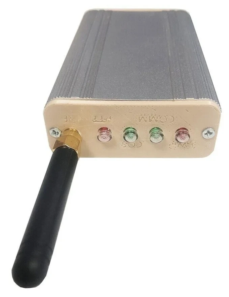
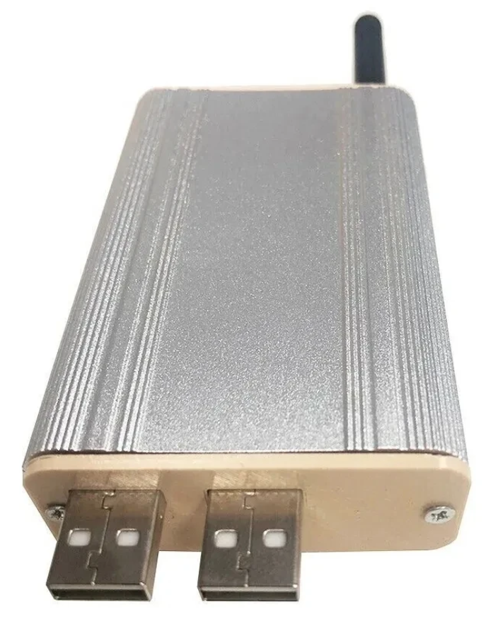
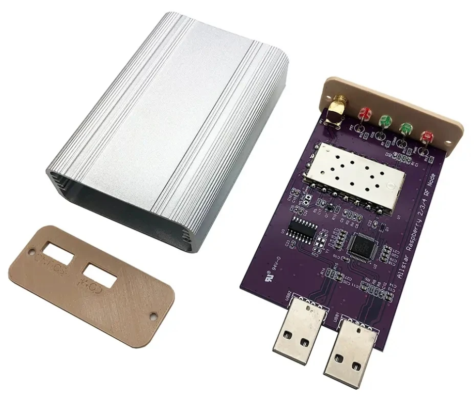
Jumbospot SHARI SA818 Amateur Radio AllStarLink Radio Interface Front Panel ViewJumbospot SHARI SA818 Amateur Radio AllStarLink Radio Interface Rear ViewJumbospot SHARI SA818 Amateur Radio AllStarLink Radio Interface stripped down View
The two USB connectors on the SHARI device are position such that they plug into two of the available 4 USB ports on the RaspberryPi without the need for cables. This keeps the whole solution together in one neat package.
Before you start you will need to obtain a node number and secret (password) from the AllStarLink Portal. To get this you will need to provide proof to the AllStarLink administrators that you are a licensed Amateur Radio (HAM) operator. This is done by uploading a copy of the first page of your HAM licence to the website for the admin team to check. This can take 24hrs to be completed so make sure you get this all done before trying to build your node. You cannot build a node successfully without a node number and secret.
Of course you will also need a transceiver that can operate on the 438.800Mhz frequency or other frequency of your choice on the 2m or 70cm HAM band.
You will also need to open port 4569 on your internet router and setup port forwarding to the IP Address that you will be using on your RaspberryPi node. It’s important to use a static IP Address on your RaspberryPi.
There are quite a few different Linux based operating system (O/S) images that are available for the RaspberryPi devices that have been specifically tailored for the AllStarLink node and include all the necessary software and library packages out the box.
Once downloaded you need to burn the ISO image onto a suitable SD card for your RaspberryPi. I use BalenaEtcher as it’s extremely quick and reliable at burning ISO images to SD cards.
Of course if you are a hardline Linux command line junkie you can always use dd to create the SD card.
Once you’ve got your O/S onto your SD card, slot it into your RaspberryPi making sure your SHARI device is connected to the two USB ports and then power it up. Make sure you have a good PSU for the RaspberryPi as the two devices together draw around 3A of current during the transmit cycle. (I use a 3.6A PSU from Amazon).
The default login for the Raspbian O/S is shown below. Login via SSH and configure your RaspberryPi for your local network. It’s important to use a static IP Address configured either directly on the RaspberryPi or via DHCP in your router.
Next you need to change directory into the asterisk config file directory using the command shown below:
cd /etc/asterisk
In this directory you will find all the default config files that come as part of the distro. For this build we’re not going to use them and so we need to move them out of the way ready for a set of config files that have already been configured correctly.
Using the following commands create a new directory, move into that new directory and then move all the unwanted configuration files into it:
mkdir ORIGINAL-CONF-FILES
cd ./ORIGINAL-CONF-FILES
mv ../*.conf ./
ls -la
cd ../
You should now be back in the /etc/asterisk directory which will now be empty apart from the custom directory which we left in place.
You now need to copy the correctly configured configuration files into the /etc/asterisk directory. Start by downloading the zip file containing the new configuration files
Once downloaded, copy the .zip file into the repeater users home directory (/home/repeater) using either scp on the Linux command line or if using Windows you can use the FileZilla Client in SFTP mode using the login details above.
Once you have the .zip file in the repeater user’s home directory you need to copy the file into the /etc/asterisk directory as user root:
The gpioBASH script and configuration details were supplied by Mark, G1INU in the Digital Voice room on the Matrix. It adds the COS light functionality to the setup. The COS light will now light every time the SA818 hears RF on the input.
The next thing you need to do is configure the SA818 radio device in the SHARI. The script I used was originally from https://wiki.fm-funknetz.de/doku.php?id=fm-funknetz:technik:shari-sa818 all I’ve done is change the entries to switch off CTCSS and changed the frequency to 438.800Mhz. Configuring the SA818 is done by running the SA818-running.pyPython programme that you moved into the repeater user home directory. Making sure you are still user root, run the following commands:
cd /home/repeater
./SA818-running.py
At this point your SHARI SA818 device will be configured to operate on 438.800Mhz and CTCSS will be disabled.
If you want to change the frequency or enable and set a CTCSS tone to access the node you will need to edit the Python programme using your favourite text editor and change the entries accordingly. Once changed rerun the program as shown above and your SHARI will be reconfigured to your new settings.
Next you need to move the allmon.ini.php file into the correct directory so that it enables access to the Allstar Monitor web page on the device so that you can manage connecting/disconnecting nodes. Use the following commands as user root to achieve this:
The allmon.ini.php file needs to have your node name entered into it for it to work correctly. As user root, change directory and edit the file using your favourite editor.
cd /var/www/html
Using your text editor, search for the line starting [XXXXX] and change the XXXXX to your node number. Save the change and exit the file.
At this point you are almost complete, all that is left to do is add your node number and node secret into the appropriate configuration files in the /etc/asterisk directory.
Since I am a Linux command line junkie I use vi to edit all the configuration files on the command line as user root, but you can use any editor of your choice.
cd /etc/asterisk
Start with the extensions.conf file. Search for the line starting with NODE = and delete the XXXXX entry and insert your node number. Save the file and edit it.
Next you need to edit the iax.conf file. This time search for the line starting with register= and change the XXXXX for your node number and the YYYYYYYYYYYY for your node secret. Be careful not to accidentally delete any other characters in the lines otherwise it will corrupt the configuration file.
In the same file search for the two lines that start with secret = and change the YYYYYYYYYYYY for your node secret. Once you have changed both of the secret entries, save and exit the file.
The final file to edit is the rpt.conf file. Once again open the file using your favourite editor and search for the line starting with XXXXX = radio@127.0.0.1:4569/XXXXX, change the XXXXX entries for your node number making sure not to delete any other characters next to the XXXXX entries.
Further down in the same file there is a line that starts with [XXXXX], once again change the XXXXX for your node number making sure to keep the square brackets at each end of the node number as you edit it.
Finally move down to the very bottom of the file and find the two lines that start with /home/repeater/gpio, once again change the XXXXX entries for your node number.
Once this is done, save and exit the file. At this point your node should be fully configured and will only require a reboot to get it working.
As user root, reboot your raspi using the reboot command.
reboot
Once your raspi comes back online, login using SSH as user repeater and then become root user using the sudo command detailed above.
You now need to create the admin user password for the Allstar Monitor web page on the device. This is done using the following commands as user root:
cd /var/www/html/
htpasswd -c .htpasswd admin
You will be asked to enter a password twice for the admin user, make sure you make a note of this password as you will need it to login to the web page.
Once this is done your configuration is complete, logout from the terminal session by entering exit twice (once to logout as user root and another to logout as user repeater).
Using your favourite web browser enter the IP Address of your raspi into the URL bar as shown below:
http://<Your-Raspi-IP>/allmon2
Note: remove the <> from the URL once you have entered the required information.
Once this is done you should be presented with your node control panel as shown below.
First visit to the AllStar Monitor Web Page
Login using Admin and the password you set above and you are now ready to start using your node.
It’s a good idea to connect to node 55553 which is a parrot test node to check your audio levels. you can do this by entering the node into the field at the top left and pressing the connect button.
M0AWS AllStarLink Node 61928 connected to 55553 Parrot
Once connected, tune your radio to 438.800Mhz FM and transmit a test message using your callsign and test123, or something similar. The parrot will then play your recording back to you so that you can hear how you sound. It will also comment on your audio level as to whether it is OK or not.
You are now connected to AllStarLink network and have the world at your finger tips. Below is a small list of nodes in the UK, Australia and America to get you started chatting with other HAMs via your node.
55553	ASL Parrot for testing
41522	M0HOY HUBNet Manchester, UK
60349	VK6CIA 439.275 Perth, Western Australia
51077	VK6SEG South West Hub B Albany WA
2167	M0JKT FreeSTAR UK HUB 2 freestar.network
53573	NWAG NW AllStar Group Lancashire, UK
27339	East Coast Hub Wilmington NC USA
M0AWS AllStarLink Node 61928 sitting on the equipment rack
Thanks to Michael, DK1MI for building and hosting the Matrix HAM Radio Space AllStarLink Node (57881) and getting us all kicked off into the world of AllStarLink!
We hope to be having regular Matrix Net’s on the node soon for all Matrix members and visitors. We’ll organise days/times via the Digital Voice room.
Following on from my article about my QO-100 Satellite Ground Station Complete Build, this article goes into some detail on the Node-RED section of the build and how I put together my QO-100 Satellite Ground Station Dashboard web app.
The Node-RED project has grown organically as I used the QO-100 satellite over time. Initially this started out as a simple project to synchronise the transmit and receive VFO’s so that the SDR receiver always tracked the IC-705 transmitter.
Over time I added more and more functionality until the QO-100 Ground Station Dashboard became the beast it is today.
M0AWS QO-100 Ground Station Control Dashboard built using Node-RED.
Looking at the dashboard web app it looks relatively simple in that it reflects a lot of the functionality that the two radio devices already have in their own rights however, bringing this together is actually more complicated than it first appears.
Starting at the beginning I use FLRig to connect to the IC-705. The connection can be via USB or LAN/Wifi, it makes no difference. Node-RED gains CAT control of the IC-705 via XMLRPC on port 12345 to FLRig.
To control the SDR receiver I use GQRX SDR software and connect to it using RIGCTL on GQRX port 7356 from Node-RED. These two methods of connectivity work well and enables full control of the two radios.
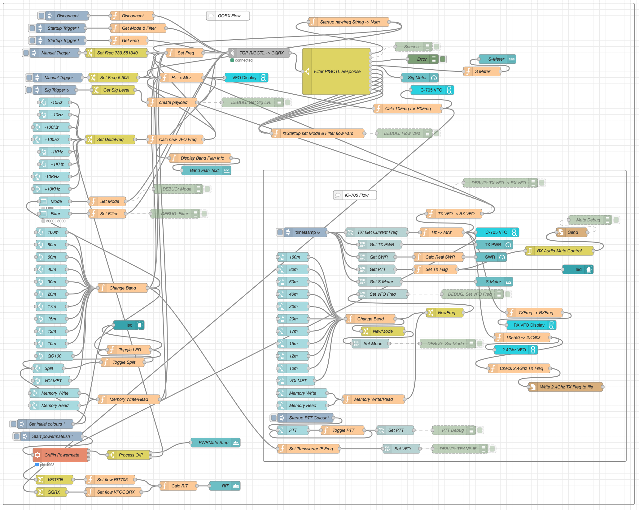
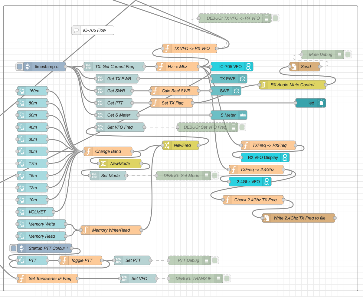
M0AWS Node-RED QO-100 Ground Station Dashboard Flow as of 12/06/24
The complete flow above looks rather daunting initially however, breaking it down into its constituent parts makes it much easier to understand.
There are two sections to the flow, the GQRX control which is the more complex of the two flows and the comparatively simple IC-705 section of the flow. These two flows could be broken down further into smaller flows and spread across multiple projects using inter-flow links however, I found it much easier from a debug point of view to have the entire flow in one Node-RED project.
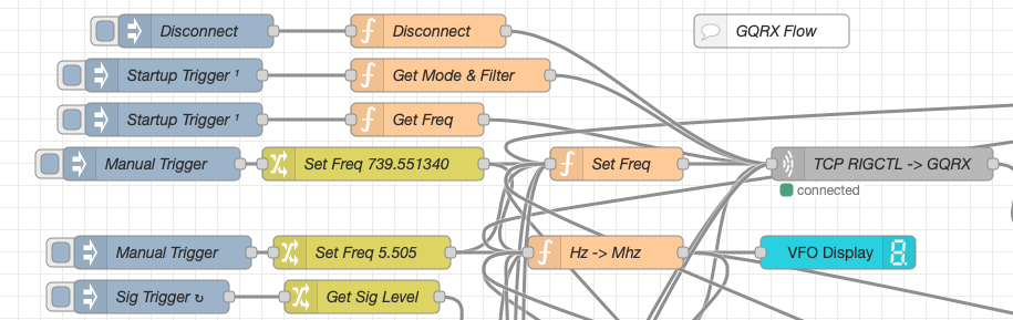
Breaking down the flow further the GQRX startup section (shown below) establishes communication with the GQRX SDR software via TCP/IP and gets the initial mode and filter settings from the SDR software. This information is then used to populate the dashboard web app.
M0AWS Node-RED QO-100 Ground Station Dashboard – GQRX Startup Flow
The startup triggers fire just once at initial startup of Node-RED so it’s important that the SDR device is plugged into the PC at boot time.
All the startup triggers feed information into the RIGCTL section of the GQRX flow. This section of the flow (shown below) passes all the commands onto the GQRX SDR software to control the SDR receiver.
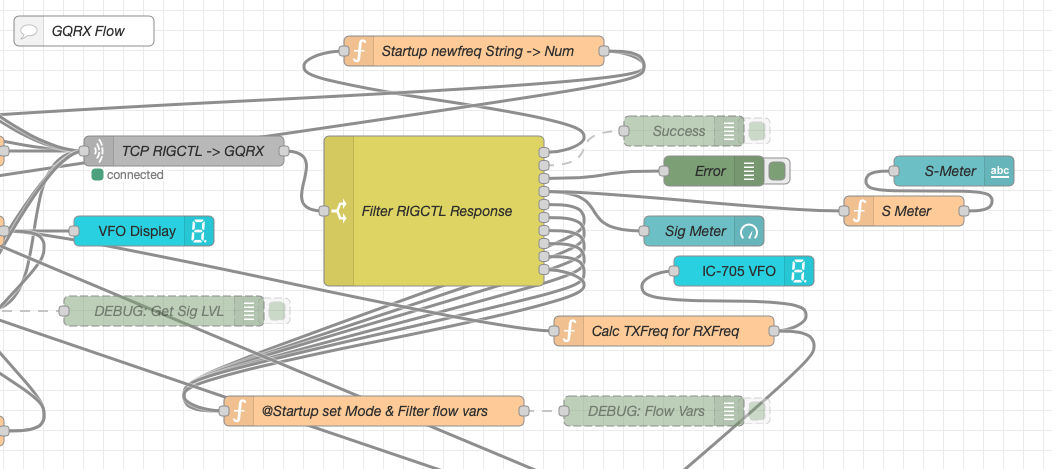
M0AWS Node-RED QO-100 Ground Station Dashboard – GQRX RIGCTL Flow
The TCP RIGCTL -> GQRX node is a standard TCP Request node that is configured to talk to the GQRX software on the defined IP Address and Port as configured in the GQRX setup. The output from this node then goes into the Filter RIGCTL Response node that processes the corresponding reply from GQRX for each message sent to it. Errors are trapped in the green Debug node and can be used for debugging.
The receive S Meter is also driven from the the output of the Filter RIGCTL Response node and passed onto the S Meter function for formatting before being passed through to the actual gauge on the dashboard.
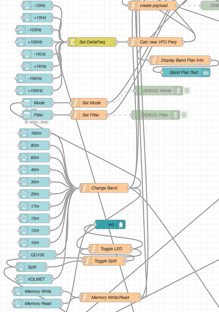
Continuing down the left hand side of the flow we move into the section where all the GQRX controls are defined.
M0AWS Node-RED QO-100 Ground Station Dashboard – GQRX Controls Flow
In this section we have the VFO step buttons that move the VFO up/down in steps of 10Hz to 10Khz. Each button press generates a value that is passed onto the Set DeltaFreq change node and then on to the Calc new VFO Freq function. From here the new VFO frequency is stored and passed onto the communications channel to send the new VFO frequency to the GQRX software.
The Mode and Filter nodes are simple drop down menus with predefined values that are used to change the mode and receive filter width of the SDR receiver.
Below are the HAM band selector buttons, each of these will use a similar process as detailed above to change the VFO frequency to a preset value on each of the HAM HF Bands.
The QO-100 button puts the transmit and receive VFO’s into synchro-mode so that the receive VFO follows the transmit VFO. It also sets the correct frequency in the 739Mhz band for the downlink from the LNB in GQRX SDR software and sets the IC-705 to the correct frequency in the 2m VHF HAM band to drive the 2.4Ghz up-converter.
The Split button allows the receive VFO to be moved away from the transmit VFO for split operation when in QO-100 mode. This allows for the receive VFO to be moved away so that you can RIT into slightly off frequency stations or to work split when working DXpedition stations.
The bottom two Memory buttons allow you to store the current receive frequency into a memory for later recall.
At the top right of this section of the flow there is a Display Band Plan Info function, this displays the band plan information for the QO-100 satellite in a small display field on the Dashboard as you tune across the transponder. Currently it only displays information for the satellite, at some point in the future I will add the necessary code to display band plan information for the HF bands too.
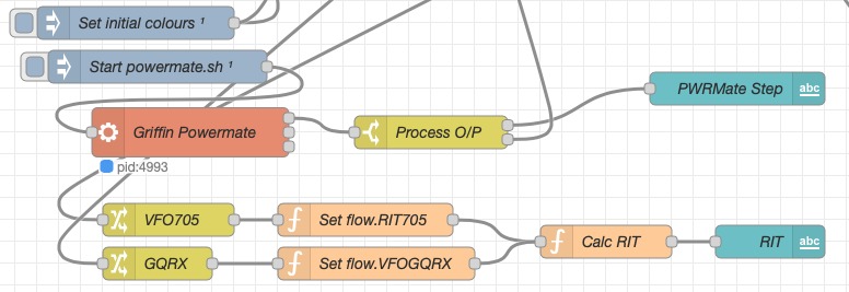
The final section of the GQRX flow (shown below) sets the initial button colours and starts the Powermate USB VFO knob flow. I’ve already written a detailed article on how this works here but, for completeness it is triggered a few seconds after startup (to allow the USB device to be found) and then starts the BASH script that is used to communicate with the USB device. The output of this is processed and passed back into the VFO control part of the flow so that the receive VFO can be manually altered when in split mode or in non-QO-100 mode.
M0AWS Node-RED QO-100 Ground Station Dashboard – Powermate VFO Flow
The bottom flows in the image above set some flow variables that are used throughout the flow and then calculates and sets the RIT value on the dashboard display.
The final section of the flow is the IC-705 control flow. This is a relatively simple flow that is used to both send and receive data to/from the IC-705, process it and pass it on to the other parts of the flow as required.
M0AWS Node-RED QO-100 Ground Station Dashboard – IC-705 Control Flow
The IC-705 flow is started via the timestamp trigger at the top left. This node is nothing more than a trigger that fires every 0.5 seconds so that the dashboard display is updated in near realtime. The flow is pretty self explanatory, in that it collects the current frequency, transmit power, SWR reading, PTT on/off status and S Meter reading each time it is triggered. This information is then processed and used to keep the dashboard display up to date and to provide VFO tracking information to the GQRX receive flow.
On the left are the buttons to change band on the IC-705 along with a button to tune to the VOLEMT on the 60m band. Once again there two memory buttons to save and recall the IC-705 VFO frequency.
The Startup PTT Colour trigger node sets the PTT button to green on startup. The PTT button changes to red during transmit and is controlled via the Toggle PTT function.
At the very bottom of the flow is the set transverter IF Freq function, this sets the IC-705 to a preselected frequency in the 2m HAM band when the dashboard is switched into QO-100 mode by pressing the QO-100 button.
On the right of the flow there is a standard file write node that writes the 2.4Ghz QO-100 uplink frequency each time it changes into a file that is used by my own logging software to add the uplink frequency into my log entries automatically. (Yes I wrote my own logging software!)
The RX Audio Mute Control filter node is used to reduce the receive volume during transmit when in QO-100 full duplex mode otherwise, the operator can get tongue tied hearing their own voice 250ms after they’ve spoken coming back from the satellite. This uses the pulse audio system found on the Linux platform. The audio is reduced to a level whereby it makes it much easier to talk but, you can still hear enough of your audio to ensure that you have a good, clean signal on the satellite.
As I said at the beginning of this article, this flow has grown organically over the last 12 months and has been a fun project to put together. I’ve had many people ask me how I have created the dashboard and whether they could do the same for their ground station. The simple answer is yes, you can use this flow with any kind of radio as long as it has the ability to be controlled via CAT/USB or TCP/IP using XMLRPC or RIGCTL.
To this end I include below an export of the complete flow that can be imported into your own Node-RED flow editor. You may need to make changes to it for it to work with your radio/SDR but, it shouldn’t take too much to complete. If like me you are using an IC-705 and any kind of SDR controlled by GQRX SDR software then it’s ready to go without any changes at all.
A couple of years ago I built a Matrix Synapse server and connected it to the decentralised global Matrix chat network that is federated world wide by enthusiasts who host their own Matrix servers. Due to the enthusiasm for a decentralised network the Matrix has grown exponentially and is now an established force in the world of Opensource global communication services.
When I built my server and configured it online my aim was to bring together an enthusiastic group of Radio Amateurs (Radio HAMs) who could build a friendly, welcoming community where people could share, learn and have fun with other liked minded individuals without all the nonsense you see on commercial social media platforms.
Overtime we’ve increased the number of rooms available in the HAM Radio space and the number of subjects covered. This has grown organically as our community has grown and we’ve ventured together into new areas of the hobby.
Global Matrix Ham Radio Space hosted on the M0AWS Matrix Server
From the community a number of projects have spawned including the Opensource.radio Wiki that Mike, DK1MI is sponsoring that aims to detail all the Opensource HAM Radio software, Hardware and projects in one centralised site on the internet. This is a great project and one I am very happy to contribute to.
Thanks to Mike, DK1MI we now also have our own Matrix AllStarLink node available. This is a great resource for the community as it is often not possible for all of us to communicate via the radio waves due to geo-location, time zones, local planning regulations etc. Having this 24/7 internet based resource makes it a lot easier for the community to chat at any time even when propagation on the HF bands isn’t in our favour.
We also have a very active satellite room with regular nets on the QO-100 satellite. With such a great range of rooms and subjects there’s plenty to read and talk about with the community.
If you fancy being part of this growing, enthusiastic group of Radio Amateurs and Short Wave Listeners (SWLs) then click on the link below and come and say hello, a warm welcome awaits!
I get quite a few emails from readers of my blog asking how my QO-100 satellite station is put together and so, I thought perhaps now is a good time to put together an article detailing the complete build.
My QO-100 satellite ground station is built around my little Icom IC-705 QRP transceiver, it’s a great little rig and is ideal for the purpose of driving a 2.4Ghz transverter/up-converter.
Of course all the software used for the project is Opensource and freely available on the internet.
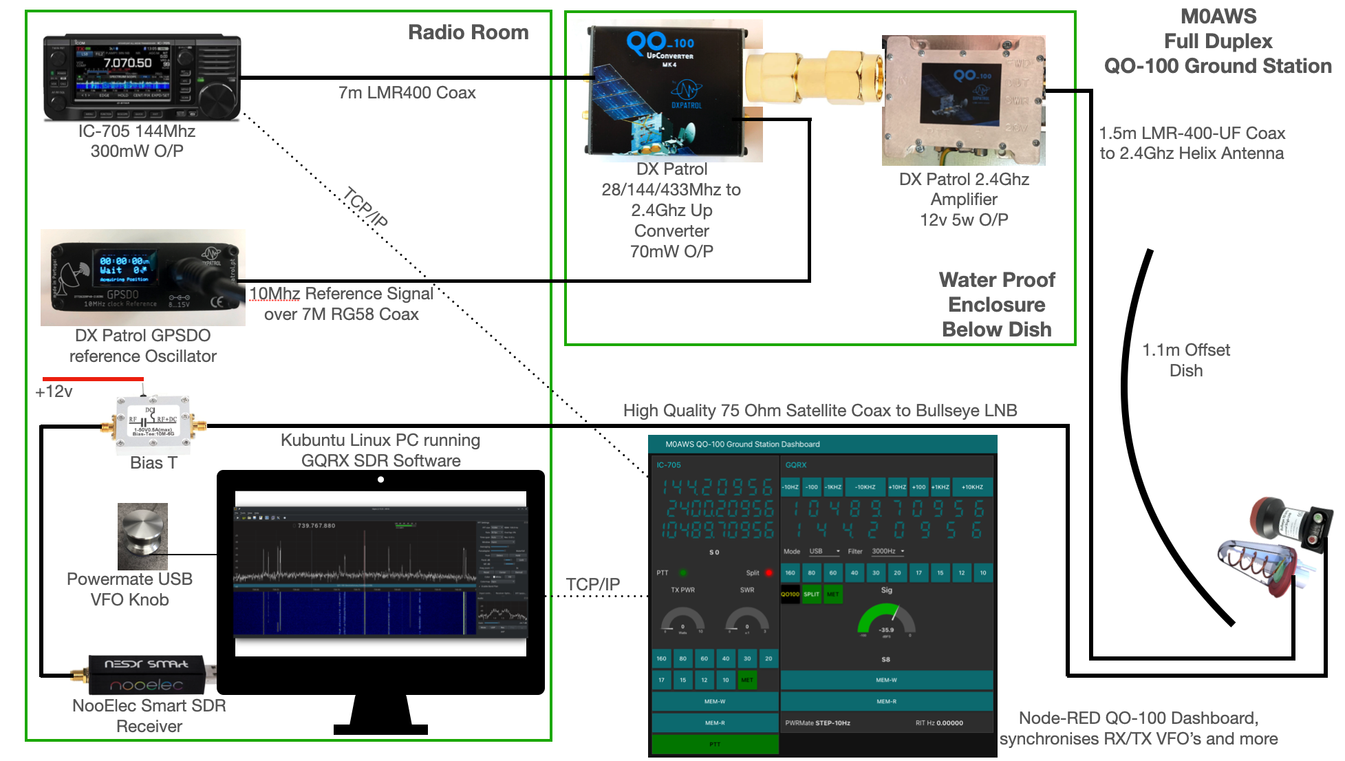
M0AWS QO-100 Ground Station Build Visual (Click to Enlarge)
The station comprises of the following building blocks:
QO-100 Ground Station Dashboard developed using Node-RED
LMR400-UF/RG58 Coax Cable
M0AWS QO-100 1.1m (110cm) off-set Dish with IceCone Helix antenna and Bullseye LNB.
To get a good clear view of the QO-100 satellite I have the dish mount 3.2m above the ground. This keeps it well clear of anyone walking past in the garden and beams the signal up at an angle of 26.2 degrees keeping well clear of neighbouring gardens.
The waterproof enclosure below the dish houses all the 2.4Ghz equipment so that the distance between the feed point and the amplifier are kept to a minimum.
The DXPatrol amplifier is spec’d to run at 28v/12w or 12v/5w, I found that running it at 28v produced too much output for the satellite and would cause the LEILA alarm on the satellite to trip constantly. Running the amp at 12v with a maximum of 5w output (average 2.5-3.5w) is more than enough for me to have a 5/9+10 signal on the transponder.
The large 1.1m dish gives me quite an advantage on receive enabling me to hear the very weak stations with ease compared to other stations.
2.4Ghz ground station enclosure ready for testing
The photo above shows the 2.4Ghz equipment mounted in the waterproof enclosure below the dish. This photo was taken during the initial build phase before I rewired it so, the amplifier is shown connected to the 28v feed. To rewire the amp to 12v was just a matter of removing the 28v converter and connecting the amp directly to the 12v feed instead. This reduced the output from a maximum of 12w down to a maximum of 5w giving a much better (considerate) level on the satellite.
It’s important to keep all interconnects as short as possible as at 2.4Ghz it is very easy to build up a lot of loss between devices.
For the connection from the IC-705 to the 2.4Ghz Up-Converter I used a 7m run of LMR-400 coax cable. The IC-705 is set to put out just 300mW on 144Mhz up to the 2.4Ghz converter and so it’s important to use a good quality coax cable.
Once again the output from the 2.4Ghz amplifier uses 1.5m of LMR-400-UF coax cable to feed up to the 2.2 turn Icecone Helix Antenna mounted on the dish. This keeps loss to a minimum and is well worth the investment.
Bullseye 10Khz High Stability Unversal Single LNB for 10.489-12.750Ghz
The receive path starts with a Bullseye LNB, this is a high gain LNB that is probably one of the best you could use for QO-100 operations. It’s fairly stable frequency wise but, does drift a little in the summer months with the high temperature changes but, overall it really is a very good LNB.
The 12v feed to the LNB is via the coax and is injected by the Bias-T device that is in the radio shack. This 12v feed powers the LNA and associated electronics in the LNB to provide a gain of 50-60dB.
Bias-T to inject 12v feed into the coax for the Bullseye LNB
From the Bias-T the coax comes down to the NooElec SmartSDR receiver. This is a really cheap SDR device (<£35 on Amazon) based on the RTL-SDR device but, it works incredibly well. I originally used a Funcube Dongle Pro+ for the receive side however, it really didn’t handle large signals very well and there was a lot of signal ghosting so, I swapped it out for the NooElec SDR and haven’t looked back since.
The NooElec SmartSDR is controlled via the excellent Opensource software GQRX SDR. I’ve been using GQRX SDR for some years now and it’s proven itself to be extremely stable and reliable with support for a good number of SDR devices.
To enhance the operation of the SDR device I have added a Griffin Powermate VFO knob to the build. This is an old USB device that I originally purchased to control my Flex3000 transceiver but, since I sold that many moons ago I decided to use it as a VFO knob in my QO-100 ground station. Details on how I got it working with the station are detailed in this blog article.
Having the need for full duplex operation on the satellite this complicates things when it comes to VFO tracking and general control of the two radios involved in the solution and so I set about creating a QO-100 Dashboard using the great Node-RED graphical programming environment to create a web app that simplifies the management of the entire setup.
M0AWS QO-100 ground Station Control Dashboard built using Node-RED.
The QO-100 Dashboard synchronises the transmit and receive VFO’s, enables split operation so that you can transmit and receive on different frequencies at the same time and a whole host of other things using very little code. Most of the functionality is created using standard Node-RED nodes. More info on Node-RED can be found on the Opensource.radio Wiki or from the menu’s above.
I’ll be publishing an article all about the QO-100 Dashboard in the very near future along with a downloadable flow file.
I’m extremely pleased with how well the ground station works and have had well in excess of 500 QSO’s on the QO-100 satellite over the last last year.
With the recent explosion of artificial intelligence (AI) art generators that are making the news of late for all the wrong reasons, I decided to see if I could put it to good use and design some futuristic QSL cards.
Having recently been contacted by the Special Callsigns QSL Manager and being advised that there were 18 QSL cards waiting for me, I decided it was time to create some QSL cards of my own for future use.
Having never used any form of online AI and not having any artistic abilities I was amazed how easy it was to create images using nothing more than a paragraph or so of text to describe what it was I wanted to create.
Since all the QSL cards I received were for contacts on the QO-100 satellite, I set out to create a visually futuristic QSL card that was based around a radio HAM operator and satellite communications.
M0AWS – 1st attempt at creating a futuristic QSL card image using AI Art
To my surprise the results of my first image generation were surprisingly good. The AI generated an image that resembled the simple text that I entered, although I never requested a one legged HAM operator!
Pleased with my very first attempt I gradually improved the description of what I was looking for, adding more and more detail to the text and including things that I wanted to see in the image. Over a fairly short period of time this approach started to generate some very interesting images.
M0AWS – AI Art QSL Image attempt 2M0AWS – AI Art QSL Image attempt 3M0AWS – AI Art QSL Image attempt 4
With each iteration I gradually got closer to what I was trying to achieve but, never quite got exactly what I wanted so, I decided to rewrite the descriptive text adding even more information than before. The text was now a full blown paragraph with quite specific things described including the angle at which the scene was being viewed from.
The other option I wanted to try out was the theme functionality that the AI offered. This allows you to set a theme for the image from things like steampunk, cartoon, manga, real world and many more. The results were quite impressive and added yet another angle to the image generation.
M0AWS – AI Art QSL Theme 1M0AWS – AI Art QSL Theme 3M0AWS – AI Art QSL Theme 2
I disappeared down the theme AI Art generation rabbit hole for quite some time and generated some very interesting and fun results. The best by far though was the Thunderbirds themed image, this did put a smile on my face!
M0AWS – AI Art QSL Thunderbirds Themed
At the other end of the spectrum I tried the Salvador Dalli theme, it produced an image that was very like the work of the famous artist but, wasn’t quite what I was looking for.
M0AWS – AI Art QSL Salvador Dalli Themed
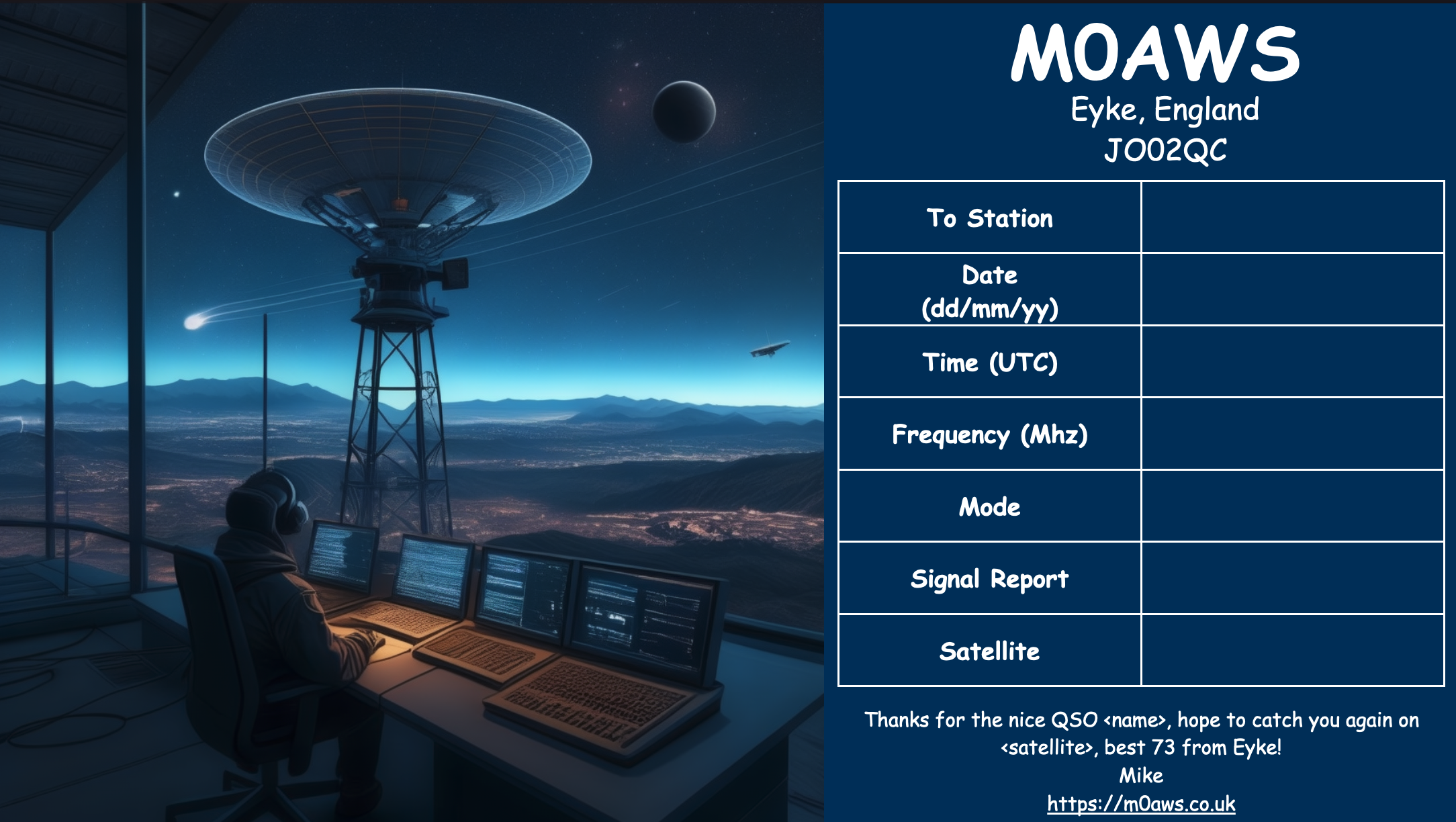
After much fun I eventually settled on the image I was after, a futuristic scene of a radio HAM with a satellite ground station over looking a mountain range and city below.
M0AWS Satellite QSL Card generated using online AI
I’m really pleased with the results from my ventures into AI generated art. The next challenge is to create a QSL card for HF bands Contacts.
This is a video of the German Weather Broadcast from DWD, Hamburg, on shortwave (HF), using teletype (RTTY). I demonstrate two decoding software options: JWcomm32 (older), and, FLdigi. Note the in FLdigi, the “Reverse” feather is selected to properly decode the signal (in either USB or LSB, you still need to select, “Reverse”). The radio […]
This video is an introduction to an international public-service and technology hobby known as ‘amateur radio’ (or ‘ham radio’). Amateur radio (also called ham radio) describes the use of radio frequency spectrum for purposes of non-commercial exchange of messages, wireless experimentation, self-training, private recreation, radiosport, contesting, and emergency communication. The term “amateur” is used to […]
Before modern radio broadcasting, the trails were being blazed both in public broadcast, but also critical links out of the local area. Here’s a side-look back in time…. in this 1939 Film: New Zealand Shortwave Communications; Morse code (CW) The romance of the radiotelegraph service (in this video, the service in New Zealand) is a […]