In his latest video, Matt from the TechMinds YouTube channel tests out an LHCP L-band helix feed designed for receiving Inmarsat satellites. Matt pairs the feed with an 85cm satellite dish, an L-band LNA, and an Airspy Mini.
The L-band helix feed comes from a small German engineering company called nolle.engineering. The feed is priced at 94.70 Euros (incl. VAT) (~$102 USD), plus shipping costs. It is a passive antenna so it needs to be combined with an LNA to be usable with a typical SDR.
In the video Matt shows that the reception with the LHCP helix + dish setup is better than expected. He also compares it to a previous test he did with a longer RHCP helix antenna also produced by nolle.engineering. The RHCP antenna is used to be used without a dish, however, as expected the SNR is less than the dish + small LHCP feed setup. Matt then shows some Inmarsat signals being decoded including STD-C and Aero voice.
A great add on to the MPAS kit or just as a stand alone.
I do find the counterpoise wires o be too thin and prone to breakage and want Chameleon to go back to the #16 Kevlar wire they are known for
Also the short length of the whip on20m is a bit finicky due to the ground I had but a grassy ground is usually pretty good but the radiation resistance was kind of low.
The kit adds items I dont have in my MPAS kit making for a well rounded deployment kit similar to this:
CHA MULTI CONFIGURATION COIL
The core component of the CHA PRV antenna, known as the CHA MCC (Multi Configuration Coil), serves as its foundation. The CHA PRV antenna is skillfully engineered and built to withstand rugged conditions, making it particularly suited for demanding portable applications such as Parks On the Air (POTA), Summits On the Air (SOTA), and other outdoor radio pursuits that necessitate an antenna that’s both efficient and easily transportable. This antenna is also an excellent choice for radio enthusiasts who reside in environments like RVs, apartments, or condos, where space is limited to a small balcony or patio.
Chameleon Antenna has designed the CHA PRV to perfectly complement the latest generation of compact multi-band/multi-mode QRP transceivers, including models like the Icom IC-705, Xiegu G90 or X6100, LAB 599 TX500, and the Yaesu FT-817/818.
SPECS
Power Handling: 500W SSB 300W CW 200W DATA
Materials: Anodize Aluminum OD Green, White Delrin, Stainless Steel and Silver Plated Copper wire
The DX Engineering box on the PO Box arrived and the antenna is a beauty
REZ Antenna Systems Recon 40 High Performance HF Antenna Coils are high-performance HF antenna coils capable of tuning 40-10 meters when paired with the REZ-Z17 17-foot telescoping whip (not included). I have the MFJ and Chameleon version.
Made with 14GA enameled copper wire, the Recon 40 is rated for use at up to 500W SSB, 300W CW, and 200W digital (50% duty cycle). The coil body is made from Delrin and 6061 anodized aluminum all CNC machined in the USA. The coil body is 100% weather resistant, thanks to its unique design which incorporates the use of O-rings and gasket seals at each joint. The coil’s machined wire groove provides mechanical support and optimal spacing to ensure a low loss coil. Switching bands is made easy with the integrated weatherproof coil bypass switch.
When you’re ready to move to the higher bands simply flip the switch and tune the telescoping whip to your desired frequency. The Recon 40 also features a rapid-deploy radial system. At the heart of this system is the radial “puck” that accepts up to eight 4mm banana plugs.
This enables quick attachment of REZ Antenna Systems’ 4-wire radial kit (not included) and leaves room to expand your radial field for increased performance. I used the radials from my Ranger 80 antenna.
I did a 3fer park activation running 50 watts off my FT-891 and a bunch of DCPower LiePO4 batteries I picked up at Liquidation Show for cheap.
There was the usual a solar storm and you could hear the band huffing and puffing in the background but we managed to also snag a couple of 2m contacts.
No adjustments were made….SWR was under 2:1 in both cases. Work 40m and then hunt the 13 Colonies on 20m…flick the switch.
The long radials make a big difference.
The QSO map shows that I was able to get a nice signal out on SSB.
This is a nice addition to the Ranger 80 antenna, although they do the same thing. If you swap out the 9 foot antenna for the 17 foot antenna on the Ranger 80, its the same story but a lot heavier. If you just wanted a quick 2 bander then the Recon 40 is a good choice (the whip can be adjusted for 20-10m and 6m as well.
The Recon 40 as its own standalone antenna is more rugged than the JNCRadio MC-750 and a lot heavier. The advantage is that the JNCRadio adds a 40m coil and uses shorter 10 foot radials but still offers a quarter wave on 20m and an 1/8 wave on 40m and a lot cheaper. Also the engraved markings on the MC-750 makes set up a breeze and its carry case is top notch. The MC-750 antenna also uses metric threading so interoperability with my antenna mounts and Buddipole stuff is impossible. I have made over a thousand contacts and very happy with it.
BUT the Recon can handle a lot more power and the whip antenna is more rugged. Its also a longer whip to try to pack. I have made about 100 contacts from the park during the RAC Contest, 13 Colonies QRMathon and POTA 3fer.
I own both and I choose the antenna I need to get the job done.
Please avoid the MFJ 17 foot whip as it likes to fall apart while using it. I am on my third so I am super careful with it but I was that way with the first two.
Many thanks to Scott (VO1DR) who shares the following guest post: Construction Notes – VO1DR Antenna Mount for Camera Monopod by Scott Schillereff, VO1DR Further to my article about radio during trip to Portugal, a number of readers asked for details on how I mounted my whip antenna system to my camera monopod for /P … Continue reading Construction Notes: VO1DR Monopod Antenna Mount→
Curious about what you can hear on shortwave ham radio? This video is a brief survey of the diverse world of communications on the shortwave spectrum. Expand your radio horizons and enhance your emergency communication preparedness by tuning in to the world of shortwave ham radio. If you’ve started delving into radio communications beyond local […]
Yesterday, I operated from the Silver Lake Day Use Area of US-3322, Pinckney State Recreation Area. This is a great park, and in many respects, I like it a lot more than US-3315, Island Lake Recreation Area. It’s just a little further from my house than Island Lake, and I think I’ll be spending more time at US-3322, now that I’ve hit 1,000 QSOs at US-3315.
One of the 40 contacts I made was with Jim, N4JAW. He’s not only a very active POTA operator, but also very active on Mastodon. Yesterday, after I returned home, I was pleasantly surprised to find this video posted to Mastodon. I’m re-posting it here with Jim’s permission.
Not so twisted anymore
As I mentioned a couple of weeks ago, I’ve been contemplating ditching the twisted-pair feedline I have been using on my POTA doublet antenna, after having such good success with my friend Paul’s Cobra antenna. That antenna uses 450 Ω ladder line. I happened to have a 100-ft. roll of high-quality, 300 Ω twinlead, so I thought I’d give that a go. I’ve used this antenna twice now, and while it’s hard to prove conclusively that the antenna works better with with the 300 Ω feedline, it “feels” as if it’s working better.
Of course, it could just be that band conditions have been better during my last two activations. That’s why I’d like to actually make some measurements. It’s not that easy, though. There are a couple of articles online that explain how to use an antenna analyzer to do this (1, 2), and I’ll give these a go once I’ve read and digested this material.
The downside to using 300 Ω twinlead is that it’s bulkier and less flexible than twisted-pair wire. It also seems more sensitive to environmental factors, such as touching the ground. But, taking a little care when setting up the antenna takes care of those issues.
QRN?? At the park?
It wasn’t all good news yesterday, though. There’s something at the park generating a hellacious noise on 20 meters. The noise is so bad that the band is practically unusable. This noise is somewhat noticeable on the other bands, but just barely, and certainly not enough to make the bands unusable.
That being the case, every one of the 40 contacts I made yesterday were on bands other than 20 meters. I started out on 40 meters, then jumped to 17 meters, which fortunately was open and active. I tried 15 meters, too, and made a few contacts there, but it wasn’t very active, so I moved back to 17 meters.
This noise is new. Last Thursday was the first time I’d noticed it. I would have made a recording of it, but I didn’t have an audio recorder handy on my phone. I will do next time I get to that part of the Pinckney Recreation Area.
On Mastodon, someone suggested that the noise was coming from a solar inverter. I hadn’t thought about that at the park, so I wasn’t really looking for solar panels, but I’m guessing that this is correct. Next time I’m there, I’m going to have to walk around and see if I see any. I might bring a small radio, too, to see if I can pinpoint the noise source.
Even if I do find the noise source, I’m not sure what I can do about it. I suppose that I can point this out to the park officials, but I’m not sure what, if anything, they’ll be motivated to do about it. Stay tuned for more on this. If you have any ideas of what I should look for, please let me know.
The DX Engineering box on the PO Box arrived and the antenna is a beauty
REZ Antenna Systems Recon 40 High Performance HF Antenna Coils are high-performance HF antenna coils capable of tuning 40-10 meters when paired with the REZ-Z17 17-foot telescoping whip (not included). I have the MFJ and Chameleon version.
Made with 14GA enameled copper wire, the Recon 40 is rated for use at up to 500W SSB, 300W CW, and 200W digital (50% duty cycle). The coil body is made from Delrin and 6061 anodized aluminum all CNC machined in the USA. The coil body is 100% weather resistant, thanks to its unique design which incorporates the use of O-rings and gasket seals at each joint. The coil’s machined wire groove provides mechanical support and optimal spacing to ensure a low loss coil. Switching bands is made easy with the integrated weatherproof coil bypass switch.
When you’re ready to move to the higher bands simply flip the switch and tune the telescoping whip to your desired frequency. The Recon 40 also features a rapid-deploy radial system. At the heart of this system is the radial “puck” that accepts up to eight 4mm banana plugs.
This enables quick attachment of REZ Antenna Systems’ 4-wire radial kit (not included) and leaves room to expand your radial field for increased performance. I used the radials from my Ranger 80 antenna.
I did a 3fer park activation running 50 watts off my FT-891 and a bunch of DCPower LiePO4 batteries I picked up at Liquidation Show for cheap.
There was the usual a solar storm and you could hear the band huffing and puffing in the background but we managed to also snag a couple of 2m contacts.
No adjustments were made….SWR was under 2:1 in both cases. Work 40m and then hunt the 13 Colonies on 20m…flick the switch.
The long radials make a big difference.
The QSO map shows that I was able to get a nice signal out on SSB.
This is a nice addition to the Ranger 80 antenna, although they do the same thing. If you swap out the 9 foot antenna for the 17 foot antenna on the Ranger 80, its the same story but a lot heavier. If you just wanted a quick 2 bander then the Recon 40 is a good choice (the whip can be adjusted for 20-10m and 6m as well.
The Recon 40 as its own standalone antenna is more rugged than the JNCRadio MC-750 and a lot heavier. The advantage is that the JNCRadio adds a 40m coil and uses shorter 10 foot radials but still offers a quarter wave on 20m and an 1/8 wave on 40m and a lot cheaper. Also the engraved markings on the MC-750 makes set up a breeze and its carry case is top notch. The MC-750 antenna also uses metric threading so interoperability with my antenna mounts and Buddipole stuff is impossible. I have made over a thousand contacts and very happy with it.
BUT the Recon can handle a lot more power and the whip antenna is more rugged. Its also a longer whip to try to pack. I have made about 100 contacts from the park during the RAC Contest, 13 Colonies QRMathon and POTA 3fer.
I own both and I choose the antenna I need to get the job done.
Please avoid the MFJ 17 foot whip as it likes to fall apart while using it. I am on my third so I am super careful with it but I was that way with the first two.
Logbook of the World seems to be back. I was able to log on and see my QSOs - which reminds me, I haven't done an upload in a while. I'll make sure to do that over the long holiday weekend. I also checked to see if our July 13th VE Session was removed from the calendar. It wasn't, even though I had sent an e-mail to the ARRL requesting that be done. I received a reply informing me that they still could not access that server. I'll be away that day and rather than put the onus on someone else to act as "Liaison for the Day", I decided to cancel.
Our annual trip to Lake George will be happening soon. This year, in addition to the AlexLoop and the AX1, I'm going to bring along the PAR ENDFEDZ 40-20-10 as well as my drive on mast base and my 20 foot crappie pole. I'd like to bring the Jackite, but it doesn't slip into the mast holder - it's too wide/thick. Usually, each time we go up to the Lake, I take some time to head up to Mt. Prospect (which is not a SOTA peak) and set up in the parking lot that is near the summit. There's a solitary picnic table there (in the parking lot!) and in the past I've parked the car some 20-30 feet away and have used the end fed as a sloper. There are other picnics tables in a wooded grassy area off to the side, but those are usually occupied by picnickers. Who wants to picnic in a parking lot, right? I usually have that table to myself. I can do a POTA activation as it's part of the Adirondack State Park - US-2001.
We had a CERT meeting in town last night and Marv K2VHW and I were asked to do some kind of licensing class for the CERT members in town. The two words I hate to hear the most were bandied about - "Ham Cram". I know Marv feels the same way I do. But what I'm thinking is maybe to have a period of reading the licensing manual beforehand with some Zoom meetings interspersed where we can answer questions and explain more "difficult" topics culminating in a day of review - the "cram" - followed by the exam session.
Looking at the QRP Labs website, I'm calculating that based on the number of built kits that leave the factory every month, I may see my QMX sometime in August. It would be neat to have it for the Skeeter Hunt. I was smitten by that HB-1B that I was given the opportunity to play with. I'm looking forward to adding the QMX to my small herd of radios.
Finally, I signed up and am Bumble Bee # 57 for this year's FOBB. The Heinz Bee - LOL! I will probably head over to Cotton Street Park for the event, although if I decide to head up to Washington Rock State Park it would be a two-fer ...... FOBB and a POTA activation.
Thirteen Colonies started Sunday night, I guess. I've no interest in participating in that at all, for reasons which I will not go into here. The best I can say about it is that it generates a lot of activity on the bands. I'll leave it at that.
When I started my ham radio journey, I lived in a suburb of Philadelphia. The house was a twin that sat at the convergence of three hills. Essentially, it was in a depression or, well, crater. It was also a corner lot with power lines running both ways. If I’d wanted more RF noise I wouldn’t have known where to start to create it. In the midst of this, I put a diplole antenna running the length of the attic. It wasn’t stellar. But then again, it was 2017 and the solar cycle wasn’t doing anyone any favors even with good setups.
A lot has changed since then. When we moved to Ohio, I strung the same dipole in the attic and went back to business as usual in the new QTH. It wasn’t much better than before. This is not a surprise. But I got into POTA and started doing a lot of portable operating. In fact, the bulk of my contacts over the last 3 years have been from my portable station. It’s been wonderful! I ended up not paying a lot of attention to just how poorly my attic dipole was performing.
The dipole in question is tuned for 40 and 20-meters. It’s from MFJ and it does what it does. But it’s not very versatile and it’s inside the house. That’s great for some things but getting out or being flexible aren’t really on the menu.
What To Do?
I don’t live in a place with restrictions on antennas but I also don’t live on some massive plot of land in the middle of nowhere. I’m still on something akin to a hillside, but it’s not nearly as dramatic as at the old place. A vertical seemed like a good idea since I didn’t really have a place to hang a dipole that would work. Enter the DX Commander Classic 2.
The Cons
Let’s start with the liabilities, shall we? The place where I can put a vertical is on the side yard of my house. The space between the house and the neighboring fence is about 40 feet. Running front to back (E-W) there is a long stretch to the road and then a shorter stretch to the fence that contains the backyard and associated dogs. It’s a weird rectangle and the overhead space is odd as well because of the house and several trees that I don’t control. That means the position of the antenna is dictated by, as always, Not Me.
The other cons? I dunno yet. We’ll give it some time.
The Pros
A vertical has a small footprint and is easy to mount in a semi-permanent fashion. I can put a spike in the ground and position the antenna on top of it if I so choose. I can also just guy it out and hope for the best. Lots of options.
With 6 elements, it covers 40, 30, 20, 17, 15, 12, 10, 6, and 2-meters. That’s a lot of bands. It’s so much more flexible than my string o’ wire in the attic that it really can’t do much other than improve my situation. It is also easier to set up, take down, get to, and maintain. Lots to like here.
The thing is also really easy to put together and remarkably tolerant when it comes to installation. Another win for THIS vertical.
The Plan
This is the part where I should be talking about how I took measurements and planned out the orientation of everything. Instead, after months of thinking, “I should do that this summer or something” I grabbed my phone and placed a pick-up order at DX Engineering. That is the blessing and curse of being 20 minutes from the largest ham radio equipment dealer in the country (world?). It’s just so easy to click buttons and drive over to pick things up. I ordered the DX Commander Classic 2, a window passthrough panel from MFJ, and a bag of turf staples to hold down my radials and that was that.
The Big Decision
The DX Commander Classic 2 comes with the option to replace the 30-meter element with an 80-meter element. This is done by making an inverted-L using a nearby tree or other support. I don’t really have a great place to do that. I’m sure I could make it work, but I’m also sure that I’d use 30-meters more than 80. That was the only real decision that was required prior to sitting down and putting it together.
The Build
The DX Commander Instructions stating: Step 1. This is a puzzle – Good luck. Step 2. Failed Step 1? User guide here dxcommander.com/guides.
This antenna is probably the least frustrating assembly of anything I’ve done lately. I can’t remember anything else just kind of going together and working quite like this. The mast is really simple. There are clamps to put in place to make sure the segments don’t fall down. There are also spacers that need to be put over the mast to hold the elements in place. No stress there. In fact, even the base with all of its wingnuts and whatnot is just threading screws. The entire assembly of the hardware took less than 15 minutes (the clamps have screws and I have clumsy fingers).
The assembled base of the DX commander.
The instructions include a cut chart. Not frequencies and wavelengths and cool math stuff. Just a list of “Cut it here” lengths and a couple of spools of wire. My daughter and I went onto the driveway and pulled out a tape measure. We measured the wire and cut it to length. Then I crimped fork connectors onto the ends and shrink-wrapped them. That’s it.
Stringing the elements to the mast is also very simple. The forks are attached to the base with wingnuts and then the elements are strung up through the various spacers. When they get through the last spacer, there is a tiny foldback into a loop that is then either taped or shrinkwrapped in place. Some shock cord is then run through the next available element, tied off, and a stopper knot put in place to keep the cord attached to the element. The element stays tight and nothing flops around in the wind.
With all of that done, it gets set up and guyed out. Again, my daughter came to my rescue and held the mast while I tied off the guy lines. With it up, I attached some radials and…that was it?
The guy lines and standing DX Commander.
The approach the maker takes to radials seems controversial, I guess. Math supports him and physics is what it is. There is a minimum amount of wire you need for radials and then you hit a point of diminishing returns. I used enough to cover my space.
The installed baseplate with radials and element indentification beads in the colors of the rainbow.
Huh… I mean… Wow.
With the antenna up and the radials deployed, I plugged it in to my RigExpert Stick Pro. I was kind of dumbstruck. All of the bands except 10-meters and 6-meters were at or below an SWR of 1.5:1 out of the box. Even 30-meters was practically 1:1. The 20-meter element is going to get some attention because it’s a bit long according to my measurements on the RigExpert but it is not a big deal. I’ll probably only take off an inch if I feel like it. In truth, the tuner will take care of that without any sweat at all.
To give some perspective, here are the AntScope2 readings for the bands covered by the antenna with NO TUNING adjustments. These are the elements installed as per the cut chart in the instructions.
Did I mention this thing tunes 2-meters like an antenna that should be able to use 2-meters? I’m sure it’s not great, but… Well, no I’m not sure of that. I will need to hook up a 2-meter rig and see what I can hit with it. Why not?
I will say, I had an Oh No! moment when I hooked it up to my IC-7100 to get on the air. With everything in place, I played with FT8 for a minute or two. But…the tuner didn’t kick in. The radio was happy enough with things as they were which was unexpected. Engaging the tuner manually got me down to 1.1:1 on my SWR meter and, well, that was that. The tuner is NOT doing a lot of work here. After I took it down and tuned up some of the elements, 10 and 6 improved quite a bit. All of the bands are quite healthy!
Current Thoughts
There are no final thoughts for this post. This is going to be something that I study for quite some time. I will say that my initial impressions are good. Incredible, really. I didn’t expect it to work this well without a lot of fiddling with things. But as Callum M0MCX says, it’s not like physics is going to change between his shop and my yard. The rules are the rules.
With new bands available to me, I’m going to spend some time on CW and FT8 and see how I do. I’ve already had some great contacts like Japan on 17-meters with 15 watts on FT8. I’m excited to get out and do some POTA hunting and up my game with my CW from home. I’m genuinely delighted with the out of the box performance of this antenna. It’s like starting the hobby all over again!
This is a video of the German Weather Broadcast from DWD, Hamburg, on shortwave (HF), using teletype (RTTY). I demonstrate two decoding software options: JWcomm32 (older), and, FLdigi. Note the in FLdigi, the “Reverse” feather is selected to properly decode the signal (in either USB or LSB, you still need to select, “Reverse”). The radio […]
This is a video of the German Weather Broadcast from DWD, Hamburg, on shortwave (HF), using teletype (RTTY). I demonstrate two decoding software options: JWcomm32 (older), and, FLdigi. Note the in FLdigi, the “Reverse” feather is selected to properly decode the signal (in either USB or LSB, you still need to select, “Reverse”). The radio […]
by Vince (VE6LK) Field Day 2024 started out with the best of plans to be spent with the best of friends and ended up totally different – and, unexpectedly, I had a hoot! With my carefully made plan behind me, my new last-minute plan was to run solo for Field Day in the backcountry of … Continue reading Experimenting during Field Day 2024→
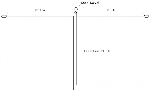
This article reports and analyses a user experiment measuring current in a problem antenna system two wire transmission line.
A common objective with two wire RF transmission lines is current balance, which means at any point along the transmission line, the current in one wire is exactly equal in magnitude and opposite in phase of that in the other wire.
Note that common mode current on feed lines is almost always a standing wave, and differential mode current on two wire feed lines is often a standing wave. Measurements at a single point might not give a complete picture, especially if taken near a minimum for either component.
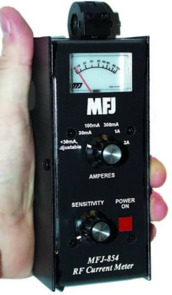
MFJ-854
The correspondent had measured feed line currents using a MFJ-854.
Above is the MFJ-854. It is a calibrated clamp RF ammeter. The manual does not describe or even mention its application for measuring common mode current.
So, my correspondent had measured the current in each wire of a two wire transmission line, recording 1.50 and 1.51A. He formed the view that since the currents were almost equal, the line was well balanced.
I have not used one of these, I rely on my correspondents guided measurements. (I have used the instrument described at Measuring common mode current extensively.)
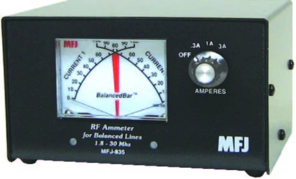
MFJ-835
This is the instrument that MFJ sell for showing transmission line balance. One often sees recommendations by owners on social media, it is quite popular.
If the needles cross within the vertical BalancedBarTM the balance is within 10%. If not, you know which line is unbalanced and by how much.
Note the quote uses current like it is a DC current, not an AC current with magnitude and phase.
So, in the scenario mentioned earlier, the needles would deflect to 50% and 50.3% on the 3A scale, the needles would cross right in the middle of the BalancedBarTM, excellent.
… or is it?
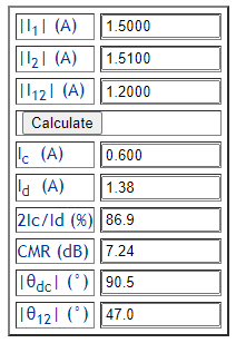
One more measurement with the MFJ-854
I asked the chap to not only measure the (magnitude) of the current in each wire, but to pinch the wires together and close the clamp around both and measure the current. The remeasured currents were of 1.50 and 1.51A in each of the two wires, the current in both wires bundled together was 1.2A.
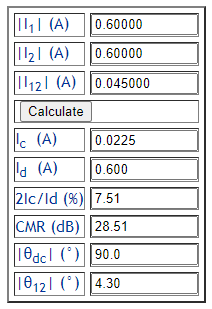
Above is the result, the current in each wire comprises a differential component of 1.38A and a common mode component of 0.6A. The common mode components in each wire are additive, so the total common mode current on the feed line is 1.2A.
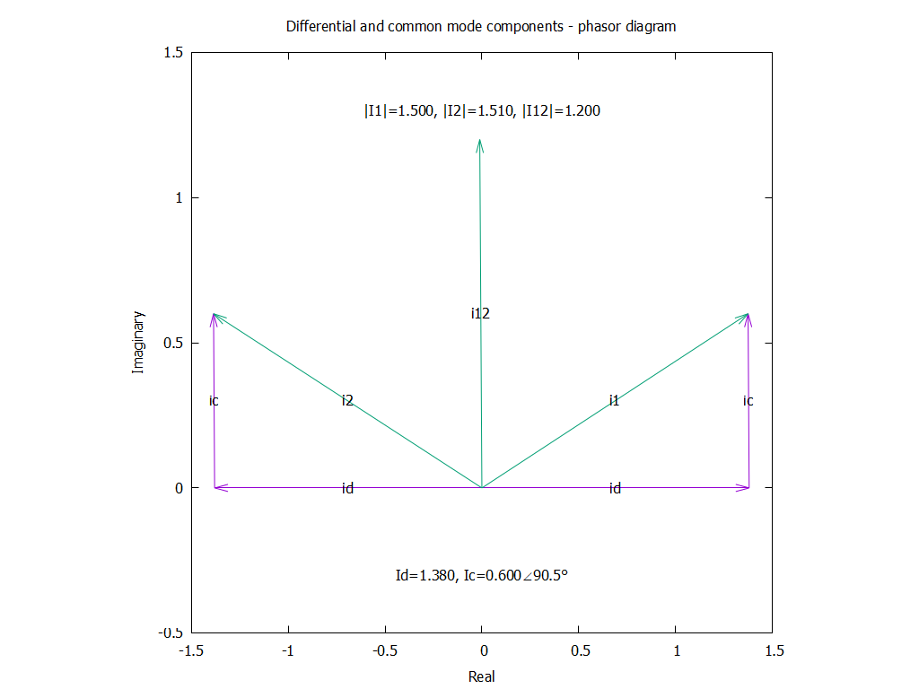
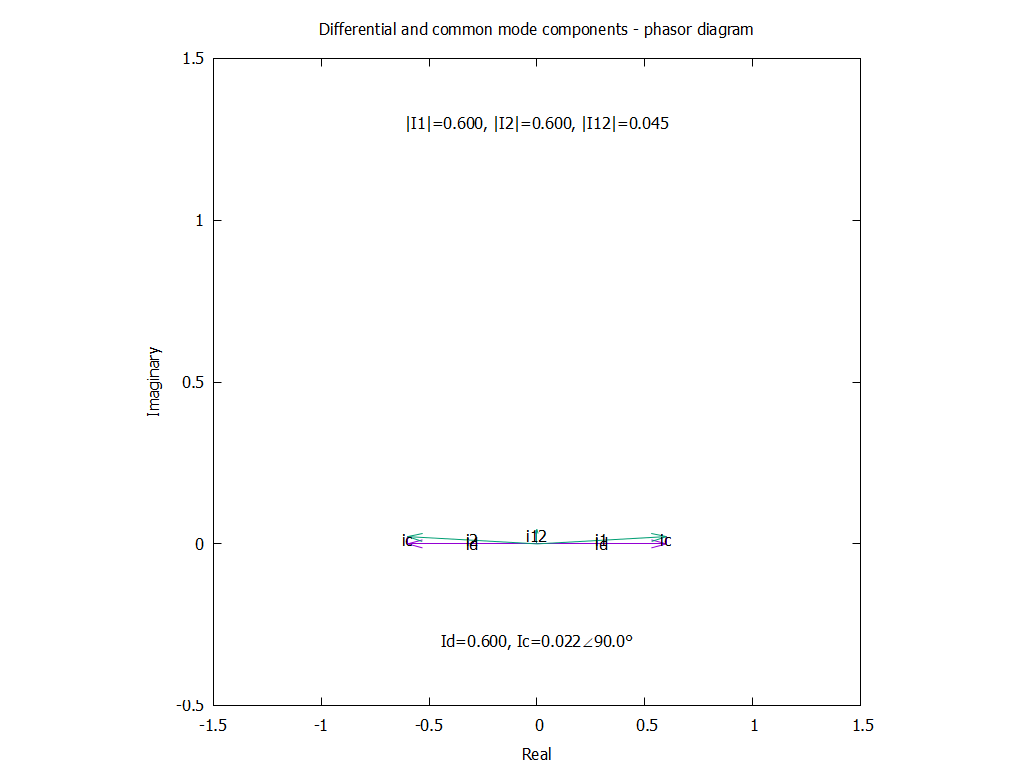
Above is a phasor diagram of I1, I2 and I12, and the components Ic and Id.
Note in this diagram that whilst the magnitude of i1 and i2 are similar, they are not 180° out of phase and that gives rise to the relatively large sum I12 (the total common mode component of I1 and I2).
This is a severe imbalance, sufficient to indicate a significant problem and to prompt a physical and electrical check of the antenna and feed line conductors and insulators.
Repairs were made and the measured result was quite good.
Above are the measurements and calcs.
Above is the phasor diagram… a bit harder to read as there is very little common mode current.
By contrast with the previous case I1 and I2 are almost 180° out of phase and the sum of them, I12 has very small magnitude.
Conclusions
The MFJ-854 can be used effectively for measuring current balance.
Understanding the relative common mode and differential components hinted there was something very wrong in the antenna system.
Forget the MFJ-835 for proving balance. If the needles do not cross in the BalancedBarTM it indicates unbalanced amplitudes. If they do cross in the BalancedBarTM it indicates approximately balanced amplitude, but does not prove the phase relationship is approximately opposite and as shown in this example, is a quite erroneous result.
One commenter questioned why we went with the more expensive Starlink system. The simple answer is that it is just better, faster, and more reliable than the alternatives. Many people here are clamoring for this sytem, and they are doing this for a reason. On speed tests I am showing downloads of about 150 Mbps. That is fast. The truth is that my wife is more of an innovator than I am -- she was the one who decided on Starlink.
When we were installing this system, I didn't even know what they meant by "Dishy." I didn't know there were motors in the antenna. And I certainly didn't know about the complicated software and hardware that allow the Dishy antenna to track the Starlink low earth orbit satellites without the use of the motors. The above video explains it all very well.
This is all a great demonstration of what can be done with digital technology, microchips, software and UHF.
Yesterday I did something I rarely do. As I was travelling home, I heard the NJ2SP repeater identify while I was in a location still pretty far away from South Plainfield. I picked up the microphone and announced that I was listening. Marv K2VHW came back to me and we had a nice conversation while I drove the rest of the way home.
What was so satisfying about it was when Marv told me my audio was rock solid and that I was making it into the repeater quite well. What a difference between this Hustler Hy-Gain antenna I'm using now and the cheap piece of ______ that I had been using before!
Our repeater is low profile by intent. It's mainly used for CERT activity , as well as for club activity throughout South Plainfield and the immediate surrounding area. For me to hit the repeater so well from Greenbrook, which is three towns away meant that my signal was travelling through North Plainfield, Plainfield and into South Plainfield. I was pleased to say the least.
As a Ham for 45 years, I know (in my head) that you should never skimp on the antenna and that it's the most important link in the whole radio station chain. But sometimes you just get frugal (read that as "cheap"), hoping that something less expensive will work just as well. This is especially true for mobile VHF/UHF antennas ----- most times it doesn't work that way, and you only end up spending more money to fix your mistake. Don't be like W2LJ, don't be tempted to go the cheap route!
Homebrew HF antennas, on the other hand, are a whole other story that I won't get into right now. Suffice it to say that many times you can roll your own skyhook that will will perform just as well as a commercial antenna for a lot less money.
I’ve quit Twitter/X, and am now part of the Fediverse. There are quite a few radio amateurs in the Fediverse, and if you’d like to follow me there, you can follow @kb6nu@mastodon.radio. Mastodon.radio is a space for radio amateurs and SWLs, but it’s not the only radio-focused Fediverse server. It connects with the servers listed on fediverse.radio, including mastodon.hams.social, a server here in the U.S.
Mastodon seems to have a much higher signal-to-noise ratio than Twitter. Here’s a few links I found and things I learned on Mastodon last night:
K8CX Ham Gallery. K8CX has an interesting collection of photos from Dayton, DX sound clips, and a QSL card museum. I’ve submitted a couple photos of me and the ICQ Podcast crew at Dayton 2024.
M17 Users mailing list. The home page for this mailing list says, “The primary assumption of this mailing list is that M17 is (in June, 2024) in usable (enough) form for actual deployment and use in amateur radio.” They believe that all the pieces are there now. Typically, to use M17, you’ll have to be “somewhat of an experimenter” to work around the inevitable glitches in using M17, but in the opinion of this list founder, “all the pieces are there now”.
44-foot doublet. Last night, there was some discussion of portable antennas, mainly the 44-ft. doublet antenna. This is the antenna that L. B. Cebik describes on the web page, “1 Wire, 7 Bands, 2 Directions, or The 44′ Doublet as a 40-10 Meter Antenna.” There’s a similar antenna out there called the NorCal Doublet. The NorCal Doublet uses ribbon cable as the feedline to reduce weight. These two antennas look like they’d be worth experimenting with.
This weekend is the ARRL June VHF contest. Its a fun way to test our your VHF Capabilities and your antenna systems…
The following is a “cut N paste” from the ARRL Website:
About
Contest Objective: For amateurs in the US and Canada (and their possessions) to work as many amateur stations in as many different 2 degrees x 1 degree Maidenhead grid squares as possible using authorized frequencies above 50 MHz. Stations outside the US & Canada (and their possessions) may only work stations in the US (and its possessions) and Canada.
Dates: The second full weekend in June. (June 8-10, 2024)
Contest Period: Begins 1800 UTC Saturday, ends 0259 UTC Monday.
Now this is a busy weekend for me (radio wise) as the Rideau Lakes Cycle Tour will be in Kingston during that time and its the only scheduled Public Service Event that our local group does every year.The picture on the left was taken the first year I assisted the Kingston Group on the event. Previous to that I lived in Ottawa and I participated with the Ottawa Group on the same event.
Using my Yaesu FT991a I plan to be giving out the “Rare FN14” Grid square on both 2m and 6m SSB.
On Saturday my Bike tour shift will finish around 6pm (EDST) or 2200 (UTC) if I did the conversion correctly… So I plan to operate from 2300 UTC for a couple of hours.
On Sunday my tour will finish around 9am (EDST) or 1300 (UTC) once again if the conversion works and will try again then around 1400 UTC once I get home.
My 2m/70cm antenna will be a simple Halo or loop which will be horizontal at approx 20 feet above ground. The 991a has an output of 50w ssb on 2m. As the loop is “sort of” useable on 70cm I will be able to give some locals an extra multi.
My 6m antenna will be a simple “Buddipole 6m Dipole. The 991a has an output of 100w ssb so it should be able to get a bit of a signal out across the Lake (at least I hope it will).
Later tonight there is a vhf net that starts on 144.250 usb that is based in Eastern Ontario. Check out the West Carleton Amateur Radio Club for more into on that. After that they call the role on 70cm and 6m. I stand a change on 6m and 2m if someone has their beams aimed southwest. More on how this works later.
Lets see who can hear the “Popgun” with the tiny antennas…