Looking to expand the device capability I stumbled across a really interesting little project that is still in the early stages of development but, is functional and worth trying out.
The TC²-BBS Meshtastic Version is a simple BBS system that runs on a RaspberryPi, Linux PC or virtual machine (VM) and can connect to a Meshtastic device via either serial, USB or TCP/IP. Having my M0AWS-1 Meshtastic node at home connected to Wifi I decided to use a TCP/IP connection to the device from a Linux VM running the Python based TC²-BBS Meshtastic BBS.
Following the instructions on how to deploy the BBS is pretty straight forward and it was up and running in no time at all. With a little editing of the code I soon had the Python based BBS software M0AWS branded and connected to my Meshtastic node-1.
M0AWS Meshtastic BBS Main Menu accessible on M0AWS-1 node.
The BBS system is very reminiscent of the old packet BBS systems of a bygone era but, it is ideal for the Meshtastic world as the simple menus and user interface are easily transmitted in seconds via the Mesh using minimal bandwidth.
The BBS is accessible by opening a Direct Message session with the M0AWS-1 node. Sending the letter H to the node will get you the initial help screen showing the menu above and then from there onwards it’s just a matter of selecting the menu item and following the BBS prompts to use the BBS.
The BBS also works across MQTT. I tested it with Dave, G4PPN and it worked perfectly via the Meshtastic MQTT server.
This simple but, effective BBS for the Meshtastic network will add a new message store/forward capability to the Mesh and could prove to be very important to the development of the Meshtastic mesh in the UK and the rest of the world.
Following on from my article about my QO-100 Satellite Ground Station Complete Build, this article goes into some detail on the Node-RED section of the build and how I put together my QO-100 Satellite Ground Station Dashboard web app.
The Node-RED project has grown organically as I used the QO-100 satellite over time. Initially this started out as a simple project to synchronise the transmit and receive VFO’s so that the SDR receiver always tracked the IC-705 transmitter.
Over time I added more and more functionality until the QO-100 Ground Station Dashboard became the beast it is today.
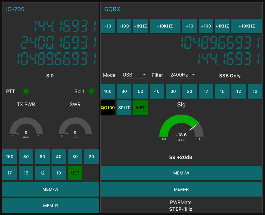
M0AWS QO-100 Ground Station Control Dashboard built using Node-RED.
Looking at the dashboard web app it looks relatively simple in that it reflects a lot of the functionality that the two radio devices already have in their own rights however, bringing this together is actually more complicated than it first appears.
Starting at the beginning I use FLRig to connect to the IC-705. The connection can be via USB or LAN/Wifi, it makes no difference. Node-RED gains CAT control of the IC-705 via XMLRPC on port 12345 to FLRig.
To control the SDR receiver I use GQRX SDR software and connect to it using RIGCTL on GQRX port 7356 from Node-RED. These two methods of connectivity work well and enables full control of the two radios.
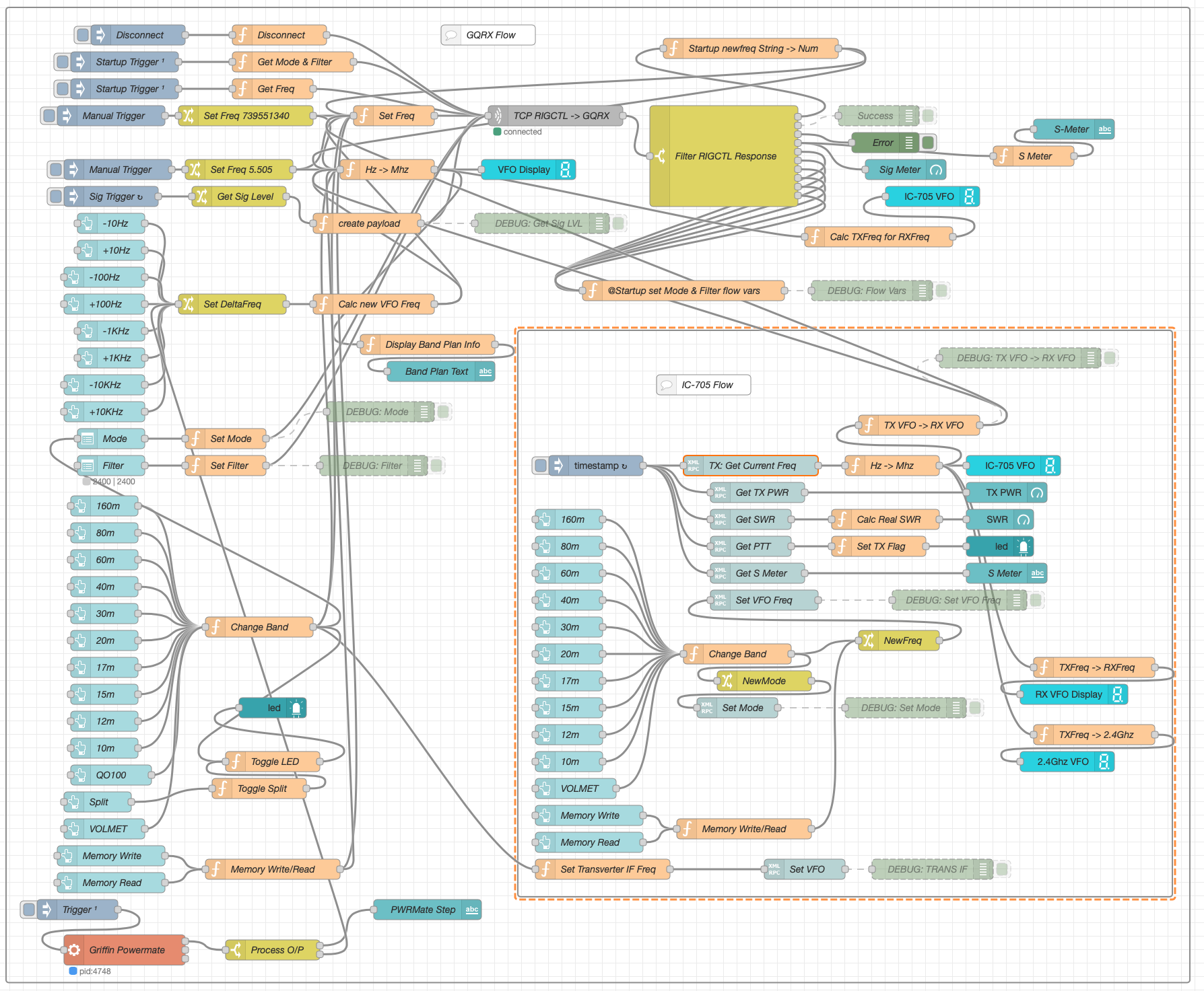
M0AWS Node-RED QO-100 Ground Station Dashboard Flow as of 12/06/24
The complete flow above looks rather daunting initially however, breaking it down into its constituent parts makes it much easier to understand.
There are two sections to the flow, the GQRX control which is the more complex of the two flows and the comparatively simple IC-705 section of the flow. These two flows could be broken down further into smaller flows and spread across multiple projects using inter-flow links however, I found it much easier from a debug point of view to have the entire flow in one Node-RED project.
Breaking down the flow further the GQRX startup section (shown below) establishes communication with the GQRX SDR software via TCP/IP and gets the initial mode and filter settings from the SDR software. This information is then used to populate the dashboard web app.
M0AWS Node-RED QO-100 Ground Station Dashboard – GQRX Startup Flow
The startup triggers fire just once at initial startup of Node-RED so it’s important that the SDR device is plugged into the PC at boot time.
All the startup triggers feed information into the RIGCTL section of the GQRX flow. This section of the flow (shown below) passes all the commands onto the GQRX SDR software to control the SDR receiver.
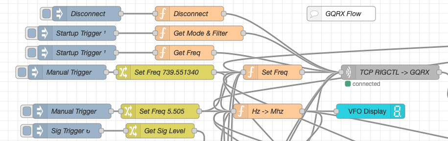
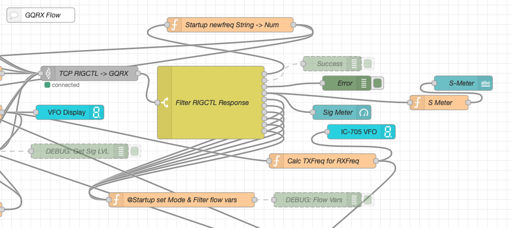
M0AWS Node-RED QO-100 Ground Station Dashboard – GQRX RIGCTL Flow
The TCP RIGCTL -> GQRX node is a standard TCP Request node that is configured to talk to the GQRX software on the defined IP Address and Port as configured in the GQRX setup. The output from this node then goes into the Filter RIGCTL Response node that processes the corresponding reply from GQRX for each message sent to it. Errors are trapped in the green Debug node and can be used for debugging.
The receive S Meter is also driven from the the output of the Filter RIGCTL Response node and passed onto the S Meter function for formatting before being passed through to the actual gauge on the dashboard.
Continuing down the left hand side of the flow we move into the section where all the GQRX controls are defined.
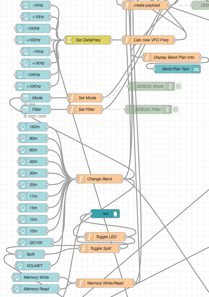
M0AWS Node-RED QO-100 Ground Station Dashboard – GQRX Controls Flow
In this section we have the VFO step buttons that move the VFO up/down in steps of 10Hz to 10Khz. Each button press generates a value that is passed onto the Set DeltaFreq change node and then on to the Calc new VFO Freq function. From here the new VFO frequency is stored and passed onto the communications channel to send the new VFO frequency to the GQRX software.
The Mode and Filter nodes are simple drop down menus with predefined values that are used to change the mode and receive filter width of the SDR receiver.
Below are the HAM band selector buttons, each of these will use a similar process as detailed above to change the VFO frequency to a preset value on each of the HAM HF Bands.
The QO-100 button puts the transmit and receive VFO’s into synchro-mode so that the receive VFO follows the transmit VFO. It also sets the correct frequency in the 739Mhz band for the downlink from the LNB in GQRX SDR software and sets the IC-705 to the correct frequency in the 2m VHF HAM band to drive the 2.4Ghz up-converter.
The Split button allows the receive VFO to be moved away from the transmit VFO for split operation when in QO-100 mode. This allows for the receive VFO to be moved away so that you can RIT into slightly off frequency stations or to work split when working DXpedition stations.
The bottom two Memory buttons allow you to store the current receive frequency into a memory for later recall.
At the top right of this section of the flow there is a Display Band Plan Info function, this displays the band plan information for the QO-100 satellite in a small display field on the Dashboard as you tune across the transponder. Currently it only displays information for the satellite, at some point in the future I will add the necessary code to display band plan information for the HF bands too.
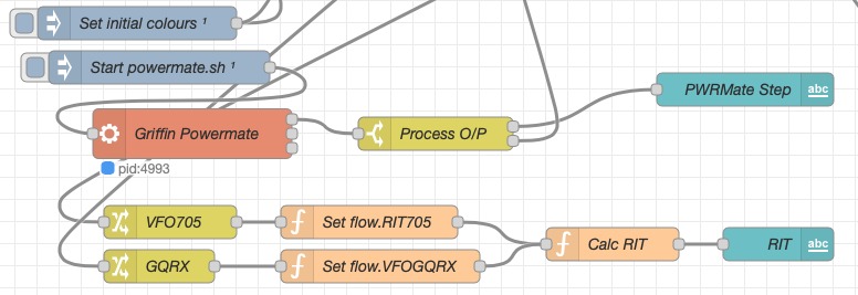
The final section of the GQRX flow (shown below) sets the initial button colours and starts the Powermate USB VFO knob flow. I’ve already written a detailed article on how this works here but, for completeness it is triggered a few seconds after startup (to allow the USB device to be found) and then starts the BASH script that is used to communicate with the USB device. The output of this is processed and passed back into the VFO control part of the flow so that the receive VFO can be manually altered when in split mode or in non-QO-100 mode.
M0AWS Node-RED QO-100 Ground Station Dashboard – Powermate VFO Flow
The bottom flows in the image above set some flow variables that are used throughout the flow and then calculates and sets the RIT value on the dashboard display.
The final section of the flow is the IC-705 control flow. This is a relatively simple flow that is used to both send and receive data to/from the IC-705, process it and pass it on to the other parts of the flow as required.
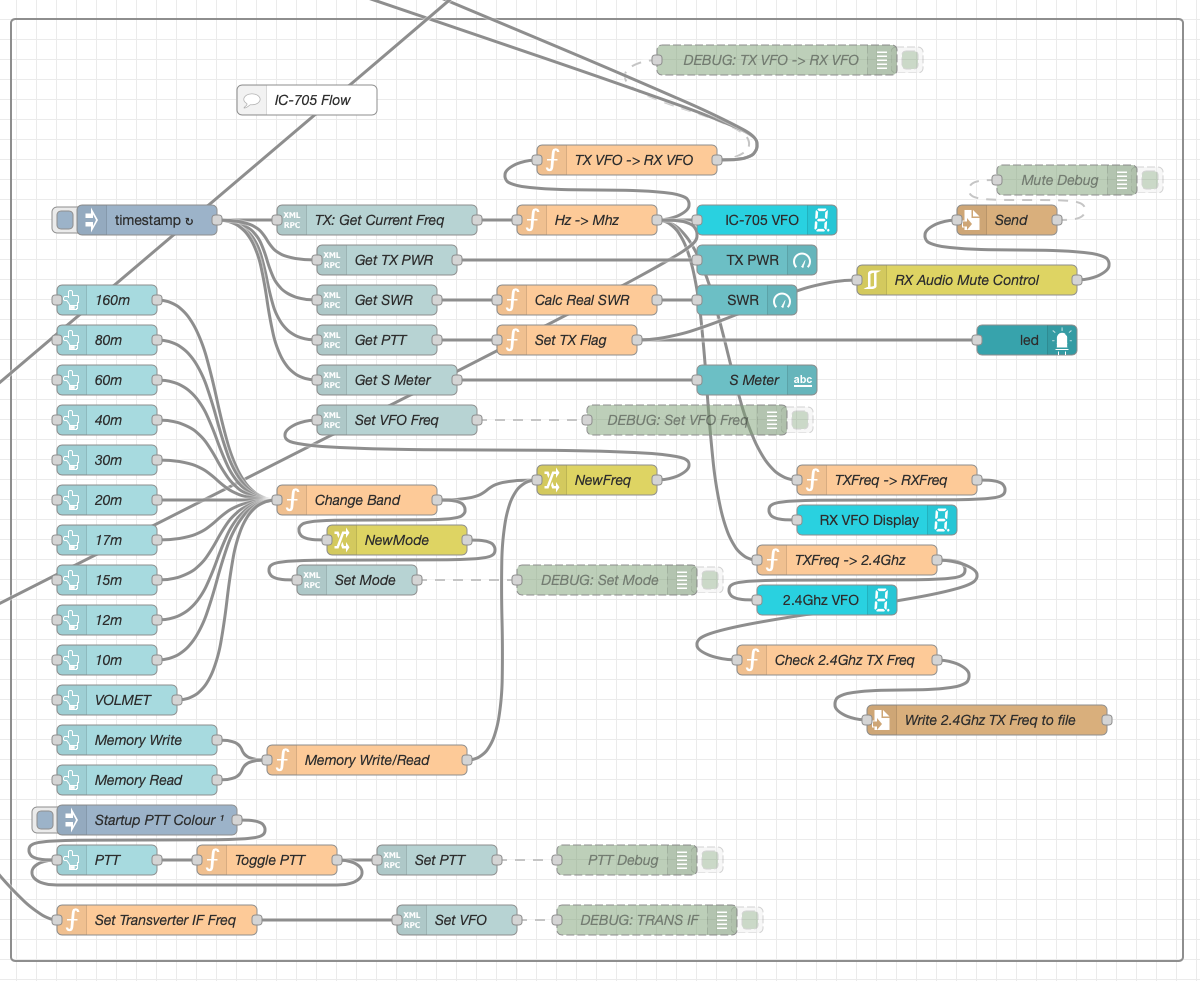
M0AWS Node-RED QO-100 Ground Station Dashboard – IC-705 Control Flow
The IC-705 flow is started via the timestamp trigger at the top left. This node is nothing more than a trigger that fires every 0.5 seconds so that the dashboard display is updated in near realtime. The flow is pretty self explanatory, in that it collects the current frequency, transmit power, SWR reading, PTT on/off status and S Meter reading each time it is triggered. This information is then processed and used to keep the dashboard display up to date and to provide VFO tracking information to the GQRX receive flow.
On the left are the buttons to change band on the IC-705 along with a button to tune to the VOLEMT on the 60m band. Once again there two memory buttons to save and recall the IC-705 VFO frequency.
The Startup PTT Colour trigger node sets the PTT button to green on startup. The PTT button changes to red during transmit and is controlled via the Toggle PTT function.
At the very bottom of the flow is the set transverter IF Freq function, this sets the IC-705 to a preselected frequency in the 2m HAM band when the dashboard is switched into QO-100 mode by pressing the QO-100 button.
On the right of the flow there is a standard file write node that writes the 2.4Ghz QO-100 uplink frequency each time it changes into a file that is used by my own logging software to add the uplink frequency into my log entries automatically. (Yes I wrote my own logging software!)
The RX Audio Mute Control filter node is used to reduce the receive volume during transmit when in QO-100 full duplex mode otherwise, the operator can get tongue tied hearing their own voice 250ms after they’ve spoken coming back from the satellite. This uses the pulse audio system found on the Linux platform. The audio is reduced to a level whereby it makes it much easier to talk but, you can still hear enough of your audio to ensure that you have a good, clean signal on the satellite.
As I said at the beginning of this article, this flow has grown organically over the last 12 months and has been a fun project to put together. I’ve had many people ask me how I have created the dashboard and whether they could do the same for their ground station. The simple answer is yes, you can use this flow with any kind of radio as long as it has the ability to be controlled via CAT/USB or TCP/IP using XMLRPC or RIGCTL.
To this end I include below an export of the complete flow that can be imported into your own Node-RED flow editor. You may need to make changes to it for it to work with your radio/SDR but, it shouldn’t take too much to complete. If like me you are using an IC-705 and any kind of SDR controlled by GQRX SDR software then it’s ready to go without any changes at all.
Discover the latest in ham radio technology with the Xiegu X6200, featuring RF direct sampling, versatile frequency support, and built-in wireless capabilities. Explore key features, setup tips, and recommended accessories in our comprehensive overview.
This solution has worked incredibly well from the outset and over time I’ve added extra functionality that I’ve found to be useful to enhance the overall setup.
The latest addition to the ground station solution is a Sennheiser Headset that I picked up for just £56 on Amazon (Much cheaper than the Heil equivalents at the HAM stores!) and have found it to be excellent. The audio quality from both the mic and the headphones is extremely good whilst being light and comfortable to wear for extended periods.
M0AWS – Sennheiser SC 165 Headset
To incorporate this into the ground station the headset is connected to my Kubuntu PC and the audio chain to the IC-705 is sent wirelessly using the latest version of WFView. This works extremely well. The receive audio comes directly from the GQRX SDR software to the headphones so that I have a full duplex headset combination.
Audio routing is done via pulse audio on the Kubuntu PC and is very easy to setup.
Since I no longer have a mic connected to the IC-705 directly I found that I needed a way to operate the PTT wirelessly and this is where the latest addition to my NodeRed QO-100 Dashboard comes in.
Adding a little functionality to the NodeRed flow I was able to create a button that toggles the IC-705 PTT state on and off giving me the ability to easily switch between receive and transmit using a simple XMLRPC node without the need for a physical PTT button.
M0AWS – Additional NodeRed PTT Flow
The PTT state and PTT button colour change is handled by the Toggle PTT function node shown in the above flow. The code to do this is relatively simple as shown below.
M0AWS – NodeRed Toggle PTT Function to change button colour
The entire QO-100 Dashboard flow has grown somewhat from it’s initial conception but, it provides all the functionality that I require to operate a full duplex station on the QO-100 satellite.
M0AWS – NodeRed QO-100 Dashboard complete flow
This simple but, effective PTT solution works great and leaves me hands free whilst talking on the satellite or the HF bands when using the IC-705. This also means that when using my IC-705 it only requires the coax to be connected, everything else is done via Wifi keeping things nice and tidy in the radio shack.
M0AWS – Updated NodeRed QO-100 Dashboard with PTT button
The image above shows the QO-100 ground station in receive cycle with the RX/TX VFO’s in split mode as the DX station was slightly off frequency to me. The PTT button goes red when in TX mode just like the split button shown above for visual reference.
As you can probably tell, I’m a huge fan of NodeRed and have put together quite a few projects using it, including my HF Bands Live Monitoring web page.
With the recent demise of CQ magazine in the US, I've decided to start looking at what other amateur radio publications are out there. Thanks to the paid subscribers to the new EI7GL newsletter on Substack, I'll use the funds to subscribe to a few amateur radio related organisations. Not only does this support them but I hope to give a bit of publicity to the various publications as well so others might subscribe.
In this post, we'll look at the May 2024 edition of the Practical Wireless magazine.
***
Practical Wireless is a monthly UK based radio magazine and describes itself as ..."aimed at the licensed radio amateur and caters for the amateur radio hobby."
Some of the articles that I think might be of interest are...
Pt 3 of a series on linear power supplies. Commercial loading coils for the HF bands Pt 2 of a series about constructing a home made CW transceiver mainly for the low HF bands with mostly discreet components. Using the Si5351 as a bench clock generator Programming an Arduino for the WSPR mode Reports of recent activity on the HF bands from a UK perspective Tim, GW4VXE as always gives a comprehensive review of recent activity on the VHF bands as well as what the recent UK licence changes mean. QRM eliminator kit A very simple home made 144 MHz Yagi made from a tape measure!
The full index of contents can be seen below...
The magazine can be purchased in the UK and Ireland in large newsagents.
Following on from my last article on improving the Heltec ESP32 v3 antennas I found during the installation of the 90 degree SMA connector that the device was very sensitive to stray capacitance from things around it. After reconnecting my VNA I found the SWR curve would change substantially depending on what the device was near and so I set about rectifying this.
I decided to remove all the insulation from the single radial inside the unit and then added two more radials to increase the ground for the antenna to tune against. I then removed the N type plug with the antenna connected to it and made a new antenna from a piece of 1.5mm solid core insulated mains wire connected directly to the N type socket, without using an N type plug. Tuning to resonance was much easier than before and I soon had the SWR down to 1.2:1. Moving the device around and placing near to other objects the SWR curve was now much more stable than before with only very slight changes in curve shape.
M0AWS Updated 868Mhz Antenna
Making this change to the 868Mhz antenna has shown an improvement in signal strength from my node-1 device of almost +0.5dB, every dB counts when you only have 100mW to play with!
The Bluetooth antenna update has made a massive improvement to the usability of the device via the iOS Meshtastic app. Being able to have a reliable, solid connection from anywhere in the house is great and I no longer lose messages because I’ve strayed outside the range of the Bluetooth connection.
I now have 2 new Heltec ESP32 v3 devices on the way to me and will be getting those configured and operational outside with external antennas in the hope of hearing some nodes locally to me.
I’ve been making a few improvements to my QO-100 Node Red Dashboard whilst waiting for the 2.4Ghz hardware to arrive. I’ve added the ability to split the RX and TX VFOs so that I can tune away from the TX frequency for working split stations or for tuning to slightly off frequency stations. I also added a series of tuning buttons to the top of the GQRX side of the dashboard to enable easy tuning using the trackball connected to my Kubuntu PC. This worked well but, I really missed having a real VFO knob like a conventional radio.
As I had a Griffin Powewrmate USB VFO from a previous SDR radio I added it to the flow as well so that I had a physical VFO knob for the SDR receiver. Details on how I got it working using evtest and a simple BASH script are in the Griffin Powermate article.
M0AWS QO-100 Node Red Dashboard Flow
The Node Red flow is looking a little busier with the addition of split mode and the Griffin Powermate USB VFO which has really enhanced the useability of the solution. It’s very impressive what can be achieved with Node Red with a little imagination. You really don’t need to be a heavy weight programmer to make things work.
M0AWS QO-100 Node Red Dashboard as of 07/06/23
I also put together some code to calculate the S Meter reading from the dBFS data the GQRX SDR software generates. It’s not 100% accurate but, it’s close enough to be useful.
On the IC-705 side of the Dashboard I also now display the 2.4Ghz uplink frequency so that it’s available for logging.
So with the QO-100 Dashboard ready to go live I have now started putting together the 2.4Ghz transmit path of the ground station. I have the 2.4Ghz transverter and matching 12w amplifier from DXPatrol, the IceCone Helix 2.4Ghz antenna from Nolle Engineering, some LMR-400-UF and connectors from Barenco and an appropriate water proof enclosure from Screwfix to fit all the kit into however, I’m now being held up by one simple little SMA male to SMA male connector that I need to connect the transverter and amp together.
M0AWS Waterproof enclosure from ScrewfixM0AWS Laying out the 2.4Ghz TX kit in the enclosureM0AWS LMR-400-UF coax from Barenco
The SMA connector has been ordered but, is taking a month of Sundays to arrive! Hopefully it’ll arrive soon and I’ll finally get on the QO-100 satellite and start enjoying the fun.
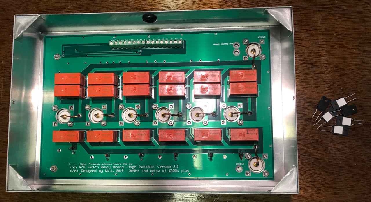
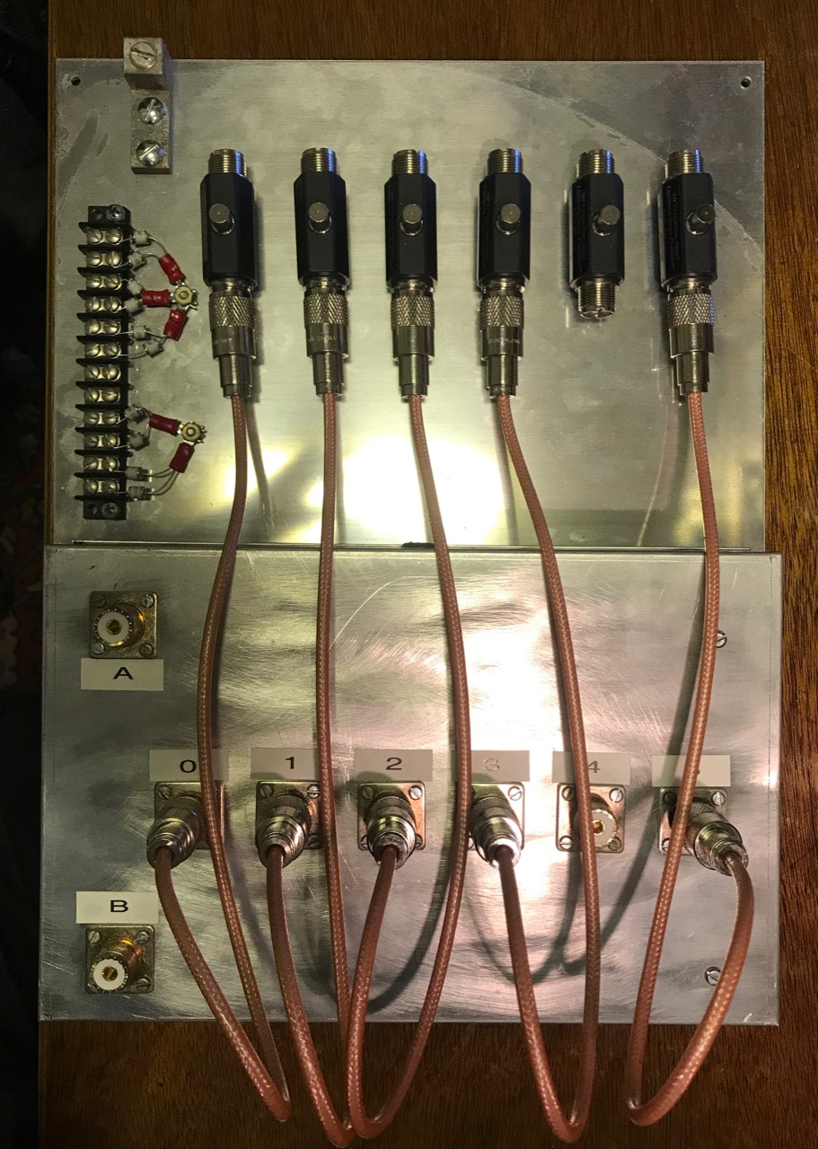
My KK1L board, showing the old resistors on the board, and the new ones on the desk.
While testing the KK1L Antenna Switch after mounting to the Single Point Ground (SPG), I noticed that some of the load resistors were no longer 50 ohms.
These resistors provide a load impedance whenever a antenna jack is not selected by either port A or Port B. This protects the antenna from static build-up as well as dissipating any coupled RF energy.
I originally used 50 ohm, 1/2 watt resistors I had on hand. Clearly they were not up to the task. On the ports for the shunt-fed tower, and the 80/40/20m trap dipole, these resistors were completely open. Both showed signs of overheating.
Most likely, these resistors succumbed to dissipating too much couple RF energy. I needed bigger ones. KK1L had 50 ohm, 50 watt resistors in his Mouser parts list, so that's what I ordered. These sorts of things come in handy, so I bought ten. Due to supply chain issues, they were back-ordered for months. But they finally arrived.
Replacing these parts is a pain. First, I had to remove the KK1L box from the SPG panel. Next, I had to remove the board from the aluminum box. Before I did that, I made sure to mark the locations the mounting screws for each resistor. To remove the board, I had to unsolder the eight connections to the SO-239 center conductors and bend them out of the way. Then came twenty-some nuts holding the board in place.
With the board separated from the box, I drilled the holes for the resistor mounting screws. I used a numbered drill bit the same size as the hole in the board to give me the largest tolerance. With the holes drilled and de-burred, my attention turned to the board.
Board with new resistors
Next step was to remove the existing resistors. Where they connect to the relays was easy, but the connections to the ground plane were harder. The ground plane tended to carry the heat away, making it hard to melt the solder without damaging the board. Getting these holes cleared of solder took a lot of effort.
Once done, the new resistors mount cleanly on the underside of the board. I oriented the resistors so the ceramic patch was toward the aluminum box. This patch does not appear electrically conductive.
After the resistors are soldered, the process is reversed to re-install the board in the aluminum box. In addition to the existing twenty-some nuts, there are also six new #4 screws and nuts to mount the resistors securely. With that in place, re-soldering the eight connections to the SO-239 center conductors completes the job.
I mounted the KK1L box to the SPG, and then re-tested all the switching combinations. This was to ensure I had connected the switching lines correctly.
I hope the new resistors are up to the job. I'll have to check on them in a few months to make sure.
As radio amateurs, taking proper precautions against lightning and electrical surges can be a difficult and expensive proposition. We often neglect them and rely on luck.
After reading Bonding and Grounding for the Radio Amateur, I decided it was worth the investment. I already had all ground connections - house, tower, station - bonded. What was missing was bonding the antenna connections to the ground as they entered the house. I needed a Single-Point Ground panel.
A Single-Point Ground is a metal panel or box providing a common bonding point for all cables as they enter a building. This metal is connected to the external ground rods, which are all bonded together. The idea is to bond the cables connected together, so that lightning or surge potentials all rise and fall together. Without a potential difference, damaging currents cannot flow.
SPG panel ready to mount on basement wall
I cut a 0.090" Aluminum panel 12" by 16" and mounted the KK1L antenna switch to the bottom edge. I added lightning arrestors for the antenna coaxial cables, plus a barrier strip holding gas discharge tubes for the rotator and shunt antenna control cables.
I chose MFJ-272 lightning arrestors. I needed six of these, and the MFJ units were about $40 each. The Alpha Delta and Polyphaser units were more expensive. The arrestors are mounted to the panel with a single large screw, supplied with the arrestor.
Short coaxial jumpers connect the arresters to the KK1L switch. I made these out of 18 inches of RG-400 coax using new Amphenol UHF connectors and a UG-175 adapter. RG-400 is doubly-shielded, eliminating the potential for any coupling between the jumpers. (Notice I didn't quite have enough RG-400 for all six jumpers, so there are only five at the moment. I'll have to purchase more)
The panel mounts on the basement wall where the cables enter the house through a 4 inch PVC pipe. A grounding block connects a short piece of copper wire to an eight foot ground rod on the outside. The ground connection is also bonded to the perimeter ground wire between the house, tower and station grounds using a split bolt.
I had a bit of trouble with the coax running from the A and B ports of the KK1L to the operating desk. Since the coax to the antennas ended at the basement wall, I trimmed some coax from the antenna feed lines. To get the right length, I pulled the feed lines outside, then trimmed them from the far end. Simple, eh? Except the first one looped around and got stuck, and the cut piece ended up being about five feet too short.
The next feed line was a newer run of Davis Buryflex. I ran it to the A3S/A743, and then cut the right length. For some reason, I had problems with the connectors on both ends, but once they were redone, the cable worked as expected. For a short while, I thought the cable itself might be defective.
To do these tests, I made good use of my RigExpert AA-55 Zoom. Which of two pieces of old coax is any good? The cable loss test is quick and give one real numbers to compare. You just need to test the coax both open and shorted.
With the SPG installed, the next step is to automate the switching of the KK1L.