Looking to expand the device capability I stumbled across a really interesting little project that is still in the early stages of development but, is functional and worth trying out.
The TC²-BBS Meshtastic Version is a simple BBS system that runs on a RaspberryPi, Linux PC or virtual machine (VM) and can connect to a Meshtastic device via either serial, USB or TCP/IP. Having my M0AWS-1 Meshtastic node at home connected to Wifi I decided to use a TCP/IP connection to the device from a Linux VM running the Python based TC²-BBS Meshtastic BBS.
Following the instructions on how to deploy the BBS is pretty straight forward and it was up and running in no time at all. With a little editing of the code I soon had the Python based BBS software M0AWS branded and connected to my Meshtastic node-1.
M0AWS Meshtastic BBS Main Menu accessible on M0AWS-1 node.
The BBS system is very reminiscent of the old packet BBS systems of a bygone era but, it is ideal for the Meshtastic world as the simple menus and user interface are easily transmitted in seconds via the Mesh using minimal bandwidth.
The BBS is accessible by opening a Direct Message session with the M0AWS-1 node. Sending the letter H to the node will get you the initial help screen showing the menu above and then from there onwards it’s just a matter of selecting the menu item and following the BBS prompts to use the BBS.
The BBS also works across MQTT. I tested it with Dave, G4PPN and it worked perfectly via the Meshtastic MQTT server.
This simple but, effective BBS for the Meshtastic network will add a new message store/forward capability to the Mesh and could prove to be very important to the development of the Meshtastic mesh in the UK and the rest of the world.
As some of you know I do some QRPp Parks on the Air activations using the QRP Labs QCX Mini. For the past couple of years I've had GREAT results using my 40 and 20 meter QCX Mini with what I call, "My Smoke Detector Battery" setup
This spring and so far this summer I've used both 40 and 20 meter QCX minis with a 9 volt/200mW battery for WSPR operations. And most recently I've used the 9 volt/200mW battery with my 40 meter QCX Mini for for early morning CW Parks on the Air activations.
While using my YouKits HB-1B during a POTA activation on April 29th, 2024, I set up another vertical antenna with my 20 meter QCX Mini to use as a WSPR station with a 9 volt/200mW battery. I ran this setup for almost an hour and was amazed with the distance and how many beacons picked up my less than a watt signal from Kentucky, USA.
QRP Labs QCXX Mini 20 Meters
A few days later on May 1, 2024; I decided to give it another try but this time on 40 meters when conditions were not quite optimal. And again, I was amazed with the number of stations picking up my signal with "My Smoke Detector Battery"
QRP Labs QCX Mini 40 Meters
As most of you may know, during the month of June 2024, the sun has presented several Earth facing regions which have been quite active with solar storms, solar flares, large sunspot regions, CME's and HF radio blackouts. These conditions have not been favorable for QRPp communications. Living in Kentucky, USA this time of year also represents days and weeks of hot, humid weather with potential for almost daily thunderstorms. So far in June 2024; we've seen record low morning temperatures of 82 degrees and several days of temperatures exceeding 95 degrees with heat indices well over 100 degrees.
Finally the Solar Space Weather forecast for the first few days of July 2024 looked like an excellent opportunity to try some Parks on the Air CW activations using QRPp. However, terrestrial weather was another issue. Heat advisories were forecasted for the last few days of June 2024 and first few days of July 2024. It was time to take advantage of this brief window to do some QRPp operating.
QRPp Equipment Set Up
The antenna I was going to use was the Tufteln 40 / 20 Linked EFHW. I made this antenna specifically for my QRP Labs 40 & 20 Meter QCX Minis.
Tufteln 40 / 20 Meter Linked EFHW
As for a keyer, I was going to use the American Morse Equipment Ultra Porta Paddle.
American Morse Equipment Ultra Porta Paddle
Upon awaking before daybreak, I checked the NOAA Space Weather Predication Center's website for Space Weather conditions. It all looked favorable. Terrestrial weather had a Heat Advisory forecasted for July 2, 2024, so I decided to head out for a near sunrise Parks on the Air activation at Beargrass Creek State Nature Preserve US-7956 which is less than 4 miles from my QTH.
Not knowing who would be hunting at 1130 UTC, I arrived on site; throw up my arborist line about 45 feet into a tree and pulled up my antenna in a sloper configuration, set up my 40 meter QCX Mini and was ready to go.
At 1142 I started sending CQ and 'BEHOLD" within a minute or two the hunters responded top my calls and kept me busy for the next 50 minutes. Below are the results of what a QRPp CW Parks on the Air activation yielded me.
The highlight of this day's activation was a QSO with Greg / VE3GSS Port Carling, ON, Canada. A little over 920 km from my Kentucky POTA site with less than 1 WATT.
At 1235 UTC the temperature had risen to 84 degrees. It made no sense in pushing it as I had already achieved more than I expected. To say I walked away with a HUGE grin on my face is an understatement. It was a GREAT Parks on the Air activation.
On July 3, 2024 my internal clock woke me at 0900 UTC with basically the same Space and Terrestrial conditions that were in play as the day before. So why not make this "Ground Hog Day in July. Same time, same set up on July 3, 2024. One difference; today I would try 20 meters.
Within less than a minute after my CQ on 40 meters at 1143 UTC, my activation began with hunters eagerly wanting to be acknowledged. I didn't disappoint and neither did they. QSOs were rapid fire for almost an hour.
At 1240, I switched over to my 20 meter QCX Mini to see what I could garner, knowing that at time time of morning in the U.S., the likelihood of getting any action on 20 meters was suspect. I did manage one 20 meter QSO. Here was my catch for a July "Ground Hog Day"
The highlight of this day was as try for a Park-to-Park QSO with a station in Japan. I tirelessly tried for several minutes to make a 40 meter contact with a Parks on the Air station JJVAS at JP- 0128. The QSB was pronounced and the strongest I could get was a 229. The operator was kind enough to send AGN? a few times but I was just trilled for that reply with less than 1 WATT.
This day like many others brought greetings from people who have become familiar with my operations as they get in their daily walks, runs and cycling before the heat sets in. Today though I met Dr. Tamekka Cornelius, Ph. D, who was out on her daily walk. She, like others are inquisitive about seeing a man sitting in a mostly open field connected to some wires, a bicycle close by and some weird equipment strapped to his legs. Dr. Cornelius and I had a nice chat about Amateur Radio, brief history of my broadcast career and my bicycling activities.
Operating QRPp reminds me of the country music singer Kenny Rogers' song:
"The Gambler"
You've got to know when to hold 'em
Know when to fold 'em
Know when to walk away
And know when to run
Once in your ham radio journey, try operating QRPp.
This solution has worked incredibly well from the outset and over time I’ve added extra functionality that I’ve found to be useful to enhance the overall setup.
The latest addition to the ground station solution is a Sennheiser Headset that I picked up for just £56 on Amazon (Much cheaper than the Heil equivalents at the HAM stores!) and have found it to be excellent. The audio quality from both the mic and the headphones is extremely good whilst being light and comfortable to wear for extended periods.
M0AWS – Sennheiser SC 165 Headset
To incorporate this into the ground station the headset is connected to my Kubuntu PC and the audio chain to the IC-705 is sent wirelessly using the latest version of WFView. This works extremely well. The receive audio comes directly from the GQRX SDR software to the headphones so that I have a full duplex headset combination.
Audio routing is done via pulse audio on the Kubuntu PC and is very easy to setup.
Since I no longer have a mic connected to the IC-705 directly I found that I needed a way to operate the PTT wirelessly and this is where the latest addition to my NodeRed QO-100 Dashboard comes in.
Adding a little functionality to the NodeRed flow I was able to create a button that toggles the IC-705 PTT state on and off giving me the ability to easily switch between receive and transmit using a simple XMLRPC node without the need for a physical PTT button.
M0AWS – Additional NodeRed PTT Flow
The PTT state and PTT button colour change is handled by the Toggle PTT function node shown in the above flow. The code to do this is relatively simple as shown below.
M0AWS – NodeRed Toggle PTT Function to change button colour
The entire QO-100 Dashboard flow has grown somewhat from it’s initial conception but, it provides all the functionality that I require to operate a full duplex station on the QO-100 satellite.
M0AWS – NodeRed QO-100 Dashboard complete flow
This simple but, effective PTT solution works great and leaves me hands free whilst talking on the satellite or the HF bands when using the IC-705. This also means that when using my IC-705 it only requires the coax to be connected, everything else is done via Wifi keeping things nice and tidy in the radio shack.
M0AWS – Updated NodeRed QO-100 Dashboard with PTT button
The image above shows the QO-100 ground station in receive cycle with the RX/TX VFO’s in split mode as the DX station was slightly off frequency to me. The PTT button goes red when in TX mode just like the split button shown above for visual reference.
As you can probably tell, I’m a huge fan of NodeRed and have put together quite a few projects using it, including my HF Bands Live Monitoring web page.
I don’t need to explain the attraction of low power operation; if you’re reading this, the chances are that you are already a convert. I’ve been operating with low power ever since first being licensed in the UK in the late 70’s as G8RYQ, and then G4IFA. One of my first rigs was a homebrew VFO-controlled FM rig for 2M. I don’t remember how much power it put out, but it was at most only a few watts. Then there was an 80M DSB rig, built from a kit, that put out a watt or two. I had a series of 2M FM rigs, including an Icom IC-22A and a Trio TR2200 (1 watt out). I had a hand-rotated 5 element 2 meter beam. To change the beam heading, I leaned out of my bedroom window and twisted the aluminum pole that was supporting it. One of the PA transistors in my Icom IC-22A was blown, so the rig only put out 4 or 5W. I remember using that rig and the beam to talk regularly on simplex with a fellow young ham who was in Wales, 90-100 miles away. I think I used the TR2200 to talk with him as well, which was even more impressive, as the Trio only put out 1 watt of RF power.
My checkered amateur radio life did include one 100W rig. It was a TS520 that I owned for a couple of years in the early 1990’s. Other than that though, every rig I have ever built or owned has been 5 watts or less. After a while doing QRP, 5 watts becomes the norm. 5W is known as “the full QRP gallon”, and it does feel like it! I still run 5W as my default most of the time, on both CW and SSB. Recently though, I’ve been turning the power down, to see how lower power levels get out. A fun moment recently, was when I clearly heard the backwave from my little two-transistor transmitter on the KPH SDR, which is 41 miles away as the crow flies. That backwave was about 1mW, and being able to hear it on a remote receiver was something of a revelation. It was that moment that kickstarted my interest in even lower power levels than the mighty force of the full QRP 5 watts.
Once a day, I check into The Noontime Net on 7284KHz. It is virtually the only time I use SSB. They welcome check-ins from QRP stations. Once a year, they have a QRP day, when operators are encouraged (though not required) to check-in using QRP power levels. There is an honorable mention on their website for the station who checks in using the least power and this year, I took the prize for checking in with 10mW of SSB. The check-in was with Don KY7X in Wellington, NV. The distance between us is 168.5 miles as the crow flies. At an equivalent distance of 16,850 miles per watt, I think that would easily qualify for the QRPARCI 1,000 miles per watt award. Given that most members who apply for that award have achieved it with CW, I think that a QSO of 168.5 miles with 10mW of SSB is even more inspiring.
The lowest power I can turn my Elecraft K2 down to on SSB is 1 watt. I achieved the power of 10mW out by connecting an inline attenuator with a fixed attenuation level of 20dB in the antenna lead. It is one of those “barrel” attenuators, with a BNC connector on each end. With the success of a check-in with 10mW under my belt, I resolved to try for even lower power in next year’s QRP Day. This led me to a nifty little kit offered by QRP Guys. It is an inline attenuator, with switchable levels of attenuation of 10, 20, and 30dB. Also included is a bypass switch that allows the operator to easily switch the attenuator out of circuit when on receive. For $25 + shipping, it was the obvious solution to my QRPp needs. I was very close to pulling the trigger, when my “QRPp extreme sports” gene kicked in, and I thought it could be useful to be able to attenuate a signal by an extra 10dB, for a total of 40dB attenuation. This would reduce the 1 watt of SSB from my K2 down to the truly flea power level of 100µW, and the 100mW CW output to the mind-bogglingly low level of just 10µW! Granted, this extra 10dB of attenuation may never be needed, but if and when I succeed in making a QSO with 30dB of attenuation in the antenna line, I may always wonder if it could also have been made with an extra 10dB. It’s the desire to constantly push our achievements just that little bit further.
With that in mind, I decided to build my own attenuator box. There is no circuit design involved really, as it is simply a series of 50 ohm pi-attenuator pads and a few DPDT switches. I took the circuit from the QRP Guys’ attenuator and added an extra pi-section and switch –
All resistors are metal film 3W types. The 100 ohms ones are 1%, while the other values were 5%. If you can get 1% tolerance for all values, then all the better. If you want to calculate resistor values for any other degree of attenuation, you can use this online calculator.
There’s not much to the build. The diecast enclosure, switches, and BNC connectors all came from Tayda. I am not thrilled with the quality of the connectors and switches from Tayda. The terminals were hard to solder to, presumably due to the use of a cheaper alloy than the quality brands such as Kobiconn and Switchcraft use. Nevetheless, I persevered, and managed to obtain a reasonably satisfactory result.
The bypass/attenuate switch is useful when going from transmit back to receive, for ensuring that your reception is not also attenuated.
Daytime band conditions weren’t too good on first finishing this attenuator, though I did manage to just be heard by Don KY7X, 168.5 miles away, with an output power of 10mW SSB, using 20dB of attenuation from an original 1W signal. I’m not sure if it would have been enough for a positive ID of my signal if he didn’t already know who I was. Nevertheless, band conditions were poor that day, so this was a good sign. I decided to hook it up to my VK3HN WSPR beacon (thanks Paul), which puts out 200mW. I applied 30dB of attenuation, for a 200µW WSPR signal – that’s just 0.2mW! Incidentally, to figure out the various attenuation levels, and what output power they give you, there are several online calculators. I found this one to be useful.
Unfortunately, the lowest power level that can be encoded into a WSPR signal is 0dBM, equivalent to 1mW. I’m not keen on misrepresenting the power level, but as I was so eager to see what a mighty 200µW of WSPR could snag me, and as I considered a power level of 20mW (10dB of attenuation of the 200mW signal) to be too high, I decided to WSPR for the night on 40M, and encode the signal at 0dBm. Check out the following results from a night of WSPR’ing. There were 486 spots in total. This is not a lot by normal standards but a good result, I think, for such a low power signal. In this screen grab, they are sorted in order of distance, so these are the most remote spots. AI6VN/KH6 in Maui tops the list, for a distance of 3778km = 2347 miles. That’s 11.735 million miles per watt! In a normal night of WSPRing on 40M with the relatively high power of 200mW, I would expect multiple spots from Hawaii, VK and ZL land, as well as a spot or two from DP0GVN in Antarctica. However, 0.2 mW is a whole new ballgame, and I was very happy to get just one spot from HI –
Here’s the attenuator sitting on my desk, on top of the VK3HN WSPR beacon. It would be nice to have a tidy desk and a nice, clean operating position but every time I tidy it, it slowly gets like this again (the 3rd law of thermodynamics in action!) At the bottom of the stack is the Sproutie SPT Part 15 Beacon, which is currently not QRV. DK, if you’re reading this, you may notice something familiar at the very bottom of this picture –
I want to be able to WSPR on a more regular basis, and have the encoded power information on my transmissions actually be fairly accurate, so the next step was to build an attenuator with a fixed attenuation level of 23dB, to reduce the output of the WSPR transmitter to 1mW. This way, when a spot from me shows up with a power level of 0 dBm, it actually is 0 dBm. This online pi-attenuator calculator was pressed into service, and yielded the following values. If you don’t have a 12 ohm resistor, then a single 330 ohm part will be close enough –
As this attenuator will only be used to attenuate the 200mW output of the WSPR beacon, I used 1/4 W resistors. The two 56 ohm resistors were left over from a cheap resistor kit that I bought years ago. They had short, thin leads, and were ostensibly 1/4W parts. The left-hand one (the one closest to the transmitter) dissipates the most amount of power, and was getting very warm during 2 minute transmissions from the 200mW transmitter. I do think it was sustainable, but would have preferred it to run cooler. I didn’t have any 1/2W or bigger resistors in appropriate values, so decided to parallel 2 x 1/4W parts. There are plenty of fresh sheets of white paper here, but drawing schematics on envelopes is more fun. A 100 ohm and 150 ohm resistor in parallel makes 60 ohms. Using 352 ohms as the “top” resistor (achieved with a 330 and a 22 ohm resistor in series) makes for an attenuation level of 22.7dB, which is pretty dang close –
The two resistors on the left-hand side run much cooler than the single 56 ohm did. The 56 ohm one was a cheapie resistor, and I suspect it’s stated power dissipation of 1/4W was being a bit optimistic. All the resistors in the final attenuator are 1/4W metal film types. The project box came in a pack of 5 from Amazon, for $7.50. I have used the same ones recently to build QRP baluns and ununs. There are all sorts of fun and novelty projects they would be useful for. The lid snaps on. I can supply the link to anyone who is interested –
The increase in power from 200µW was noticeable after the first night of WSPR’ing on 40M with 1mW. Here is a screen grab of the most distant spots received. In just under 10 hours, I had 1114 spots. It’s a lot fewer spots than what I would receive with 200mW, but that many spots with just 1mW sounds very encouraging. I love this little WSPR beacon (thanks to Paul VK3HN once again). Out of 1114 spots, all of the drift figures were a big honking zero, with the exception of a single 1 and a single -1. Instead of the single spot from AI6VN’s remote listening station in Maui, I now had 7. Sure, propagation on different nights could be some of it, but I’m pretty sure the 7dB power increase from 200µW to a gigantic 1 milliwatt was a significant factor.
The VK3HN WSPR Beacon merrily WSPR’ing away on my desk, with a mighty 1mW, thanks to the 23dB pi-attenuator.
This QRPp experiment has been a huge success so far, and I haven’t even begun to work on the goal that I had in mind when beginning this. That was to use the switched step attenuator to see how far I can go with very low power on CW, my mode of choice. WSPR is very instructive and interesting, but an actual QSO, even a brief one, carries the extra appeal of contact with a distant person, with all the unpredictable intangibles that come along with that. I do wish there was a way of encoding lower powers than 0 dBm (1mW) into a WSPR transmission, as I would then be WSPR’ing with successively lower powers. I’ve already received a significant number of spots with 200µW of transmitted power. It would be great to see what could be done with, say, just 10µW (0.01mW), if anything. In the meantime though, there will be a lot of 1mW WSPR’ing emanating from the AA7EE radio ranch, as well as some extreme QRPp CW too, with the help of the switchable step attenuator.
For the past few weeks I've been using my Buddipole Deluxe Antenna system in several different configurations for my Parks on the Air activations. Nothing special but the antenna has been sitting in the corner for too many months collecting dust. I've had a lot of success using using my Buddipole antenna during recent QRP use. It brought to mind something I was told and has been ingrained in my ham radio DNA for over 60 years. For ham radio operating your money is better spent on an effective antenna system than your radio. Whether you make it, bake it, print it, or buy it; spend the money first on that antenna system.
My ham radio antenna redux journey started something like this. In March 1983 when I took my Novice test to get re-licensed, I had moved back in with my aging parents to care for them. I had already purchased my rig (Ten-Tec Century 21) and antenna (Butternut HF6V). As I look back, purchasing that antenna at THAT time was not one of my best ham radio operating decisions. I wish I had done what I did when I was first licensed in 1963 and built my own antenna. (The mind of a child can be so innocent and yet plausible.) There was nothing wrong with that Butternut antenna. It is a great antenna.
However, their house was two stories with an attic (Total height was almost 40' high)with a metal roof and a small backyard 30 x 12, surrounded by similar dwellings and power/telephone lines surrounding the property. Considering safety and operating efficiency, It took me almost 2 years to mount the Butternut to optimum (though compromised) operating position. The Butternut antenna was mounted with metal pipes attached to side of house that place the base of antenna 10 feet above roof with several wires running from base to metal roof to act as a counterpoise. I worked the world on CW with that Century 21 & Butternut HF6V setup.
The point for me, was my excitement to get on the air as quickly as possible. I wished I would have invested more time in preparing and evaluating my antenna setup before purchasing the Butternut.
As we approach warmer temperatures with better weather here in the U.S., what better time to invest in some antenna system evaluating, antenna repairing and building. There's no time like the present to do some antenna work and take advantage of the benefits of this enhancedsolar cycle as it will come and go before you know it. You'll want to be assured your antenna will give you its best not only during these intensified solar conditions but during solar minimum as well.
If any of you follow me on Social Media, you may have noticed I do most of my Parks on the Air activations via bicycle. You also may have seen I have a lot of cycling jerseys. I like to say, I have as many ham radio antennas as I do cycling jerseys.
I have made quite a lot of antennas over the years. Some good and some I try to forget. Some Mono, some dual band, J-Pole, Moxon-Turnstile, Yagi, Egg Beaters, Flower Pot antenna, linked dipole for QRP and QRO, some EFHW for QRO and QRP, some vertical, some random wire for QRP and QRO, Delta Loop and antennas for satellite use.
QRP/QRO 40 meter Mono Band
QRP Tufteln Linked EFHW
QRP 40 - 15 Lijnked Dipole
QRO 60/ 40/ 30 / 20 Linked Dipole
QRP 40 - 10 meter Random Wire
Moxon Turnstile for Sat work
40 - 10 Meter QRP EFHW
Their use depends on some variables in portable use. Terrain, footprint, type and length of mast, availability of trees for deployment (if they can be used) which radio, which bands, mode of operation, band conditions, solar and terrestrial weather, and how I feel, etc.
Some of my most memorable contacts have been made using antenna I've built. For me, there's nothing more satisfying and rewarding than getting that cross continent or QRPp QSO with an antenna built with my own hands.
Besides, wire, coaxial cable, connectors, heat shrink, insulators , etc the most important tool for my antenna building projects is either an Antenna Analyzer or Nano NVA. Hands down it makes antenna building so much easier.
I remember reading something about antennas from renowned ham radio enthusiast Doug DeMaw W1FB (SK) that went something like this .... the most important part of an effective ham station is the antenna system. Expensive transceivers and mediocre antennas do not complement one another if you want to communicate over long distance paths.
After initially finding that I couldn’t tune the 868Mhz ground plane antenna with the radials bent down at 45 degrees I decided to experiment to find out why.
Initially I had the radials connected to the 4 corners of the base of the chassis mount N Type socket. This works great if you have the radials completely horizontal and gives an SWR of 1.1:1 but, with the radials bent down at 45 degrees the best SWR is around 2:1.
M0AWS 868Mhz Ground Plane Antenna Close Up
Removing the radials from the base of the N Type chassis socket and soldering them to the outer of the N Type plug at the same level as the feed point for the radiating element I found that an almost perfect SWR can be achieved very easily.
M0AWS 868Mhz Antenna with radials soldered to the N Type Plug
It seemed weird to me that such a small change could have such a big effect on the obtainable SWR for the antenna but, as can be seen in the image below with the radials soldered to the N Type plug and bent downwards I immediately got an SWR of 1.07:1 and a much wider SWR curve.
M0AWS 868Mhz Antenna SWR curve with radials soldered to N Type plug.
By making my own antennas I’m learning a lot about antenna design for the 800-900Mhz frequency range. Minor changes seem to have a much bigger impact than they do at much lower frequencies.
As well as the small stash of finished projects that grace my living space, I also have two small boxes containing various boards. Some of them are boards from part-finished projects that didn’t work. For whatever reason, I ran out of steam and, instead of troubleshooting them, put them carefully into a small box along with their cellmates, and conveniently put them out of my mind. A few of the boards actually worked, but I decided not to case them up. One of these is the two-transistor transmitter I built a few years ago, that was basically the TX side of the Pixie 2 design. I like to pull boards like this out of the box from time to time and power them up. Then they go back in the box, waiting for the next time I feel partial to some extra-curricular fun.
Extricated unceremoniously from it’s cardboard box on the shelf, this little transmitter (pictured above) was putting out about 200mW when connected to a 12V supply. I got a real kick from hearing the signals from this simple circuit on the KPH online SDR at the Point Reyes coastal station, 41 miles away as the crow flies. This design has the oscillator running continuously. In the Pixie, from which it was taken, the oscillator is needed on receive as well. As the circuit consists of just an oscillator and a PA stage, there is a small amount of oscillator leakage into the PA even when the PA stage is not being keyed. Imagine my surprise on discovering that I could hear this backwave on the KPH online SDR! Putting the transmitter on my OHR QRP Wattmeter revealed that although accurate measurement was not possible at such low power levels, it looked as if something of the order of a milliwatt of RF energy was making it’s way to the antenna when the transmitter was not being keyed. Now, the fact that 1mW could be heard 41 miles away, though impressive, is by no means unprecedented. Nevertheless, it fired up my imagination, and made me want to build another little transmitter.
The train of logic that I followed in order to finally settle on building GM3OXX’s little OXO Transmitter was, as it turns out, not very logical and quite convoluted. I will not attempt to explain it here, as it will only serve to confuse! However, I did want a design in which the oscillator wasn’t running on key-up, so that I could monitor the signal in the receiver to serve as sidetone.
The OXO transmitter was first featured in the Autumn 1981 issue of SPRAT, the journal of the G-QRP club. The original circuit didn’t include an LPF; the builder was expected to provide their own. Here is the original circuit, with the addition of an LPF –
The BCY39 PNP transistor keys the +12V supply to the 2N3866 PA. It is not necessary to key the oscillator, as the oscillator won’t run unless the PA transistor is switched on. In the LPF, the 1.38µH inductors can be made with 21 turns on a T37-6 toroid, and the 1.7µH with 24 turns on a T37-6 toroid. Values were taken from the assembly instructions for the QRP Labs low pass filter kits. Numbers of turns for different toroids can be figured out from the very useful calculators on the Kits and Parts website.
I mocked it up on a breadboard and it worked well. I noticed that the VXO, although not oscillating on key-up, was emitting some very low level spurii. In retrospect, this could well have been due to stray capacitances in the breadboard, and the fact that the circuit wasn’t built over a ground plane. Nevertheless, I decided to have the keying transistor key both the oscillator and PA. This is what I came up with, drawn on the back of an envelope –
George GM3OXX added a 0.1µF cap across the key contacts to help with shaping. It wasn’t on the original schematic as published in SPRAT, but I added it here. The RFC in the collector of the PA transistor can be a molded choke. I wound 17 turns on an FT37-43 toroid to serve the same purpose. I also added a spotting switch, with the 1N5817 diode to prevent the PA from being switched on when only the oscillator signal is wanted, for “netting” the transmitter frequency on a receiver. Unfortunately, the spotting switch didn’t work out quite as planned. More on that later.
I had an old LMB Heeger 143 enclosure lying around from my build of N6KR’s SST. I had drilled the front panel holes in the wrong places, so ditched it and used a fresh enclosure. I had considered this enclosure to be unusable for another project, until realizing that I could simply place a piece of PCB material over the front panel to cover up the unused holes, and keep it attached with the nuts and screws that were holding the controls in place. It worked well and looks pretty good. The slide switch is for transmit/receive switching, the red button is for spotting, and the big knob is the VXO tuning –
The board was scrubbed with a steel wool soapy pot scrubber and given a couple of thin coats of clear spray-on lacquer. A fresh board holds so much potential, and never looks as good as before construction begins. It’s almost a shame to glue any pads onto it!
All the back panel connectors (key jack, DC power connectors, and BNC’s) were from Tayda. I’m not blown away by the quality of the connectors from Tayda but considering the very reasonable prices, I am making an exception.
I built the VXO first, and tested the frequency coverage. Most any small signal NPN transistor will work in this position. I used a 2N3904. A 2N3866 was used in the original circuit for the PA. I didn’t have one of those, but I did have some 2N3866 equivalents in the form of the Motorola 4-247 CG9949. A while back, the G-QRP club were giving away small quantities of these transistors for free to their members. I took advantage of the offer, knowing that I could use a 2N3866 equivalent or three. This is the exact same transistor that Kanga UK are using for their kit version of the OXO transmitter.
At this point, after having built the VXO and PA circuits, the OXO will function as a transmitter, by keying the +12V line. If you only ever intend to use a manual key with this transmitter, it is not necessary to build the keying switch, and you’ve got yourself a nice and simple two-transistor transmitter. However, I like using a paddle, and the keying circuit is very simple. Here’s the board with the basic transmitter built. You can see the crystal, in a holder made from an SIP strip, along with the VXO transistor, right next to the polyvaricon. The PA transistor is the one with the big honking heatsink on it, just behind the toroid. The keying transistor, a 2N3906, is to the right of the toroid –
For transmit/receive switching, a primitive solution was found, in the form of a DPDT slide switch that came from Dan’s Small Parts and Kits years ago, and has been sitting in one of my parts drawers, just waiting for an opportunity to be used. It was wired up like this (another diagram drawn on the back of an envelope!) –
On receive, the antenna is connected to the antenna input of the receiver. The output of the transmitter is connected to a 50 ohm dummy load. In case the transmitter is accidentally keyed while in receive mode, it’s output will be protected by the 50 ohm load. On transmit, the output of the transmitter is routed to the antenna, while the receiver antenna input is connected to the 50 ohm load. The receiver is being used for sidetone, so the idea behind this is to do whatever can be done to prevent receiver overloading while in transmit mode.
The OXO transmitter, all wired up and ready to go. I used an LPF from QRP-Labs. Band changing can be accomplished by plugging in a different crystal and plugging in a different LPF –
Regarding the PA emitter resistor that is marked as 39Ω. You can fine tune the value of that resistor, depending on the output power you want. Be careful not to go too low, or the transistor could overheat and be destroyed. In the Kanga UK kit version that uses the exact same PA transistor, the emitter resistor is 2 x 33Ω resistors in parallel, for a total effective resistance of 16.5Ω. In the build instructions, Paul reports that with a 13.8V power supply, he gets 1.5W out on 80M and 1W on 40M. I was cautious, and began with 2 x 100Ω resistors (=50Ω). I added resistors in parallel, until I got to 4 x 100Ω (=25Ω). My OHR QRP Wattmeter indicated an RF power out of 400mW. My NM0S QRPometer indicated a power out of 580mW. I wasn’t sure which one was more accurate, so split the difference and called it 500mW. I could get more power by adding another couple of 100Ω resistors, but I rather like the idea of having a 500mW transmitter. By comparison, 1W seems so pedestrian! With an emitter resistance of 25Ω, the voltage across it was 3.2V. According to ohm’s law, the current through it was 128mA, for a dissipated power of 0.41W. The resistors are 1/4W parts, so their total power dissipation capability is 1W. Sounds well within the margin of their capability.
In the following picture, you can see the two 100 ohm 1 watt resistors that form the 50 ohm dummy load in the background –
The heatsink on the PA transistor is probably overkill for a power output of just 500mW, but it gives a good safety margin. I held the key down for 2 minutes (into a dummy load, of course), and it only became mildly warm to the touch. I think it would safely survive even if my cat fell asleep on the key
The two 12V DC connectors on the back panel are wired in parallel, to allow one 12V lead to power both the transmitter and a companion receiver. It is not shown in the schematic, and cannot be easily seen in any of these pictures, but a 1N5817 diode is wired between the +ve side of the 12V DC connectors and the board, for reverse polarity protection.
I paired it up with my Rugster direct conversion receiver and QSO’ed with K6KWV in Diamond Bar, CA on 40M – a distance of 363 miles as the crow flies. Not mega-DX, but it was a very enjoyable contact. He said that I was the first contact he’d had with a station using a homebrew rig, and I was also running the lowest power of any station he’d QSO’ed with. That was nice to hear! He has only been a ham for 4 months, and has a good fist. His code is pleasant to listen to, and easy copy.
When using the Rugster, as well as throwing the TX-RX switch when going from receive to transmit, I also have to turn the RF gain control down to zero to prevent the receiver from overloading. If on headphones, I also have to turn the AF gain down somewhat. Although it is an easy process to get used to, I find my Belka-DX even easier. Due to the AGC in the Belka, I don’t have to change a thing when going from receive to transmit, and vice-versa, other than flipping the TX-RX slide switch on the OXO transmitter.
The CW note sounds good on 40, and chirp-free. There is a little chirp with my 14060 crystal, and a lot with the 21060 and 28060 crystals. I credit this to the PA loading down the oscillator, and figure that a buffer stage between the oscillator and buffer would cure it. Thanks to John KC9ON, at 3rd Planet Solar, I have a pack of 40M crystals that are in HC49/S cases – the short cases. My 14060, 21060, and 28060 crystals are all in the tall HC49/U cases. Perhaps the higher band crystals are not fundamentals?
On a related note, comparing my HC49/U 7030 crystal with the HC49/S one, the tall crystal pulls over a wider frequency range. I didn’t think to measure the capacitance of the polyvaricon before installing it, but I think it is 270pF per gang. Putting both gangs in parallel made little difference to the pulling range. With the tall HC49/U 7030 crystal, the range was 7028.77 – 7032.83KHz, representing a swing of 3.61KHz. By contrast, the short HC49/S crystal pulled from 7029.57 to 7031.1KHz – a swing of just 1.53KHz. Pulling range became increasingly greater with the higher frequency crystals. The 28060KHz crystal pulled over a range of 13.42Khz, but chirped so much it was comic.
Oh, about that spotting button. I thought I’d be able to use it to net the transmitter precisely on a received station’s frequency. Unfortunately, the frequency of the VXO is significantly lower in spot mode than on full key-down. On 40M with a short crystal, the difference is 250Hz. I assume this issue wouldn’t exist with a buffer stage between the VXO and the PA.
For the time being, I am going to give this project a rest and concentrate on other things. We all need a break sometimes. However, if and when I revisit this little transmitter, I’d like to rewire it so that just the PA is keyed, as was intended with the original circuit. Given that the oscillator doesn’t run unless the PA transistor is switched on, I see no reason not to do this. It is an easy change to make. I’d also like to acquire and try different crystals for the higher bands, in the hope that will eliminate the chirpiness.
Another future possibility would be to add an SMA connector on the back panel for an Si5351 VFO. At that point though, the project is becoming more complex, perhaps negating the point of such a simple transmitter to begin with.
Following on from my last article on improving the Heltec ESP32 v3 antennas I found during the installation of the 90 degree SMA connector that the device was very sensitive to stray capacitance from things around it. After reconnecting my VNA I found the SWR curve would change substantially depending on what the device was near and so I set about rectifying this.
I decided to remove all the insulation from the single radial inside the unit and then added two more radials to increase the ground for the antenna to tune against. I then removed the N type plug with the antenna connected to it and made a new antenna from a piece of 1.5mm solid core insulated mains wire connected directly to the N type socket, without using an N type plug. Tuning to resonance was much easier than before and I soon had the SWR down to 1.2:1. Moving the device around and placing near to other objects the SWR curve was now much more stable than before with only very slight changes in curve shape.
M0AWS Updated 868Mhz Antenna
Making this change to the 868Mhz antenna has shown an improvement in signal strength from my node-1 device of almost +0.5dB, every dB counts when you only have 100mW to play with!
The Bluetooth antenna update has made a massive improvement to the usability of the device via the iOS Meshtastic app. Being able to have a reliable, solid connection from anywhere in the house is great and I no longer lose messages because I’ve strayed outside the range of the Bluetooth connection.
I now have 2 new Heltec ESP32 v3 devices on the way to me and will be getting those configured and operational outside with external antennas in the hope of hearing some nodes locally to me.
The Heltec ESP32 v3 LORA devices have a coil type Bluetooth/Wifi antenna on the PCB from the factory. This antenna doesn’t work particularly well and has very limited range so, I decided to do something about it.
Getting out the calculator a quarter wave at 2400Mhz is 29.7mm. Looking at the coil antenna on the PCB I decided the best way to connect the new antenna would be to solder it to the coil of the existing antenna. This would short out the coil completely whilst creating a solid mount point for the new antenna.
After a little measuring I decided to use a 31mm long piece of 1.5mm hard core mains cable for the new antenna. I stripped back the insulation from one end of the wire so that the exposed copper wire was exactly the length to short across all the windings of the coil antenna on the PCB.
Attaching replacement Bluetooth Antenna to the Heltec ESP32 v3 Device
Attaching the the wire to the coil was easy enough to do but, it’s worth pointing out that you need to be quick so that the heat doesn’t transfer down onto the PCB desoldering the coil antenna from the device.
Whilst tinkering with the Bluetooth antenna I decided I would also make a neat little quarter wave 868Mhz vertical antenna for this device whilst I had it all apart. This is my Meshtastic node-2 and it’s sole purpose is to allow me to use my iPad to send/receive messages via bluetooth which are then forwarded on to my base node-1 in the house. Node-1 is connected to the house wifi and the Meshtastic MQTT server. This combination allows me to message people on the mesh even though there are no local nodes within RF range.
Running the numbers for the 868Mhz antenna the vertical will need to be around 82.1mm long with a radial of similar length. I had to hand a very nice SMA to N Type chassis mount socket that would be ideal to mount the antenna to the case. I drilled out the holes in the case, measured out the wires and attached it all to the case. Connecting the antenna to the N Type socket I connected my VNA and set about tuning the antenna to resonance.
M0AWS Hidden Radial for the 868Mhz Heltec Antenna
Squeezing the radial and SMA connector into the case I realised I really could do with a 90 degree SMA connector so, I quickly ordered one from Amazon which will be delivered tomorrow. Connecting up my VNA, I had to trim the antenna down to get it to resonance. The SWR ended up at 1.2:1 which is ideal. I ended up cutting off more wire than I thought I would to get the antenna to resonance but, this is due to the extra capacitance caused by the insulation on the wire. If I had used bare copper wire then I wouldn’t of had to cut so much off. I eventually ended up with around 72.9mm of wire for both the antenna and radial.
M0AWS Heltec ESP32 v3 Device with replacement Bluetooth and 868Mhz Antennas
Putting the device back into the case and connecting the USB battery the device fired up and immediately connected to my node in the house. Checking the signal strength of node-1 in the house I could see a 7dB increase in signal strength compared to the little wire antenna that comes with the device. This is a significant improvement for such a simple antenna and well worth the effort.
Next I had to drill a hole in the front of the Heltec case so that the Bluetooth antenna could poke out the front and be bent up vertically. This worked out really well and improved the Bluetooth range massively.
M0AWS Completed alterations to the Heltec ESP32 v3 antennas
Putting the node back in the house and taking my iPad down to the end of the garden some 30m away I could instantly connect to the device via Bluetooth from my iPad, something I’d not been able to do prior to adding the new antennas. I can now use the Heltec device via Bluetooth from anywhere in the house or garden making it much more accessible.
It’s amazing the difference an hour and two little pieces of wire can make to these devices and is well worth the effort.
I’ve been on the QO-100 satellite for about 7 months now and I have to admit I love it!
Having a “Repeater In The Sky” that covers a third of the world really is a wonderful facility to have access to however, there is one thing that I find tiring and that is the high level of background noise that is always present.
Even though the signals are mostly 59-59+15dB the background “hiss” is very pronounced and gets very tiring after a while, especially if like me you have tinnitus.
Currently I’m using a NooElec Smart SDR for the receiver and GQRX SDR software on my Kubuntu Linux PC. This works great but, there is one short fall, there is no DSP Noise Reduction (NR) in the software or hardware.
To fix this I recently invested in a BHI Dual In-Line Noise Eliminating Module. The unit itself is nicely put together and has a good combination of inputs and outputs making it easy to connect up to my MacBook Pro to record QSOs and connect my headphones at the same time.
M0AWS BHI Dual In-Line Noise Eliminating Module
At £189.95 plus postage from BHI direct it’s not cheap but, it is nicely put together and comes complete with a power lead and a couple of cheap audio cables. The quality of the knobs and mechanisms is good apart from the little grey DSP Filter Level knob that feels cheap and is very wobbly on the switch below. I’m not sure how long this is going to last with prolonged use and will most likely need replacing with something a little sturdier at some point in the future.
Overall noise reduction is good but, the audio amplifiers on the Audio Input Level and Line Out Level distort very early on in their range and you cannot get them much above level 5 before distortion starts to appear on the received signal. This is disappointing as my headphones are of reasonable quality and are let down by the distortion creeping in from the audio amplifier in the BHI unit.
I’ve tried altering the levels on the input from the IC-705 and no matter what I cannot get a good audio signal in my headphones without some distortion on the higher frequency ranges.
Overall the device does do what I want, it reduces the background “hash” considerably reducing the fatigue whilst chatting on the satellite. Below is a recording from a conversation on the satellite showing the noise reduction performance of the BHI module.
M0AWS Example BHI DSP NR Recording
The recording starts with the BHI DSP NR off, at 00:07 the DSP NR is switched on, you can clearly hear the difference. At 00:23 the DSP NR is turned off again and at 00:36 the DSP NR is turned on again. The BHI DSP NR Module is set with the DSP Filter Level set at 3 out of 8 which appears to be the best level to use. Switching to level 4 starts to introduce digital artefacts to the audio which only gets worse the higher the DSP Filter Level goes.
With a setting above level 3 there really isn’t much improvement in noise reduction and the audio becomes progressively more affected by the digital artefacts than it does from the background noise.
M0AWS BHI Dual In-Line Noise Eliminating Module with Icom IC-705 QO-100 Ground Station
The only other problem I have with the BHI Dual In-Line Noise Eliminating Module is that is comes in a plastic case. The case itself is solid and of good quality however, it offers no RF shielding whatsoever and the unit is extremely susceptible to RF getting into the audio chain and then being heard during transmit in the headphones and via the line out connections. For the money I would had expected the unit to come in a metal case that provides proper RF shielding. This is a real shame as it lets the unit down considerably.
As setup in the photo above I am using 300mW O/P on 144Mhz from the IC-705 into a perfect 1:1 SWR presented by the DX Patrol 2.4Ghz Upconverter via some very high quality LMR-400 Coaxial cable from Barenco but, I get terrible RF interference via the BHI unit during the transmit cycle. Considering I am only using 300mW I dread to think what it may be like if I was using a 100w HF radio. This is something I need to investigate further as it really is very annoying.
Moving the unit to a different location in the radio room does help a bit but, doesn’t solve the problem completely. At 300mW RF O/P I really didn’t expect there to be a problem with RF getting into the BHI unit.
Having a proper line-out facility on the BHI unit really is nice as it makes it very easy to connect to my MacBook Pro to obtain good quality recordings of signals on the QO-100 satellite as can be listened to above.
Overall I am happy with the BHI Dual In-Line Noise Eliminating Module but, do wish that more care had been taken over using a metal case instead of a plastic case to protect the unit from RF ingress and better audio amplifiers within the unit that don’t distort/clip so early on in their O/P levels.
Is this the perfect noise reduction unit?
No but, overall it is better than nothing and does help to reduce the background noise to a more acceptable level reducing the overall fatigue during prolonged conversations on the QO-100 satellite.
UPDATE: I tried the BHI unit with my FTDX10 on the HF bands and the RF interference is horrendous, even when using QRP power levels! This device clearly hasn’t been designed to work in an RF environment and the total lack of shielding or isolation lets it down terribly. If you are an SWL then this unit is fine but, if like me you like to monitor your transmitted audio whilst on air through headphones then this isn’t the unit for you. To prove the problem isn’t in the radio shack I put the BHI unit in the house some 30m away powered by 12v battery with nothing connected but a pair of headphones and still the unit suffered from RF interference even at QRP levels.
A year ago I purchased and built a QCX Mini (40 Meter version) QRP CW transceiver from QRPLabs. My main reason for this purchase was the small nature of the radio. A subsequent added reason was its capacity to operate with 9 volts.
Over the last year I have used this rig several times using a 9 volt / 200 mah battery. Most recently August 26th and 27th, 2023 during a Parks on the Air activation.
On those two days the Terrestrial weather was extremely HOT with daytime high temperatures near 100 degrees Fahrenheit. My activations on those two days were at or near sunrise. Even at sunrise it was warm, humid and muggy with sunrise temperatures hovering in the low 80's.
However, the Space weather was working in my favor with the SFI at 139, A index of 6, K index of 2, Sun Spot number of 70, and Solar Winds of 380. The noise of the HF bands was relatively quiet.
My antenna for both days was my 40/20 Meter Linked End Fed Half Wave antenna I constructed from Tufteln. Joshua / N5FY has a nice selection of antenna and other ham radio related accessories. Visit his site here https://www.tufteln.net/
I wanted to get this antenna as close to vertical as possible so I used 150 feet of Weaver Arborist Throw Line and a 14 ounce weight to get it as high as possible into a tree.
Here is how I launched my line into this tree. Its an awkward backward between my legs and over my head throw which works very well for me.
Once my antenna was up well over 50 feet into the tree, I setup as much as possible in the shade and within less than two minutes of calling CQ, I received my first QSO.
My station is so small it fits on a kneeboard from Tufteln which hold my rig, paddle, battery, audio recorder and notepad for logging.
My setup is simple, light and what I consider to be small which can fit in a small backpack. The heaviest item of my setup is the arborist throw line and weight.
Due to the heat, I only operated about an hour on August 26th and 27th. Both days were on 40 meters with 1 watt or less. Here are maps of QSOs for both days.
August 26, 2023
August 27, 2023
All in all it was a fun two days of operating QRPp, 1 watt and less using a 9 Volt battery you'll find in your home smoke detector. And if you do decide to try this type of operation, please DO NOT REMOVE the battery from your smoke detector
I’ve been waiting for over a week so far for a male to male SMA connector to arrive from Amazon so that I can connect the 2.4Ghz up-converter to the 2.4Ghz amplifier. Since it still hasn’t arrived I decided to connect the up-converter directly to the IceCone Helix antenna to see if I could get a signal into the QO-100 satellite.
To my surprise I could easily hear my CW signal on QO-100 even though the total output from the up-converter is only 200mW.
I didn’t expect to be able to hear my signal since it’s a tiny amount of power that has to travel some 22500 miles to the satellite but, I could hear it and was amazed that it was peaking S8 on my SDR receiver.
2.4Ghz Up-Converter connected directly to the antenna bypassing the 2.4Ghz Amplifier
Being excited I put out a CQ call that was soon answered by OH5LK, Jussi in Finland. Jussi gave me a 579 report which I was extremely pleased with. He was of course much stronger at a 599+ at my end. We had a quick QSO and exchanged details without any problems at all. Its really nice to get a QRPp contact without any QSB or QRM.
M0AWS QO-100 1.1m off-set Dish and IceCone Helix antenna ground station
Neil, G7UFO who I chat with regularly in the Matrix Amateur Radio Satellites room has posted a connector out to me so I’m hoping it will arrive on Monday and then I’ll be able to connect the amplifier and hopefully get a few SSB contacts.
UPDATE: I’ve since had 2 SSB contacts via QO-100 using just the 200mW O/P from the up-converter. Both times I got a 3/3 report not brilliant but, perfectly acceptable for the amount of power I’m putting out.
I first tried WSPR out in 2009, with a Signalink USB interface attached to my FT-817 and PC. For anyone interested in QRP and QRPp, the process of being able to decode a signal that is up to about 34dB below the noise level is quite fascinating. Morse code, sent by way of CW, engages and tickles my brain in ways that other modes don’t. WSPR though (and other weak signal modes), has it handily beat in terms of it’s sheer ability to extract data from a signal that the human ear cannot even detect. A few years later, in 2018, I assembled an Ultimate 3S QRSS/WSPR beacon transmitter from QRP Labs for a ham friend. This project opened me to the appeal of a standalone WSPR beacon that, unlike my earlier foray into WSPR, didn’t require tying up my main station gear. The addition of a GPS unit, as well as setting the timing of the transmissions, could also automatically insert the Maidenhead grid locator – no need to manually program that, making it ideal for travel.
Fast forward to the current day. I’ve recently become a bit more active on the bands, and decided that I wanted to “stop the rot” of my CW skills, which were slightly degrading due to lack of use. I signed up for an online CW course with the CW Academy, offered by CW Ops. I just completed their intermediate course, and enjoyed it immensely. The Intermediate course is designed to take ops from 10-20 wpm. I was already comfortably having conversational QSO’s at about 16-18 wpm. At CW Academy, the emphasis is on head-copying, so that you can converse without needing to write anything down other than the occasional piece of essential info (name, rig, etc.) This, they explain, is an important skill, if you are to increase your speed. I, along with most of the other students, found it surprisingly challenging to listen to short stories in code, and extract meaning from them without writing anything down. It helped that we had a fantastic advisor, in the form of Randy N1SP. Practice sessions in between our online Zoom sessions could be challenging, but the prospect of classes led by Randy were a great incentive. He made learning fun.
Along with my renewed interest in CW came interest in weak signal modes generally, as well as a slight stirring in the desire to build radio things again. Over the last 3 years, I’ve been putting time and effort into working on my camper van, which took energy and money away from amateur radio. Well, I’m gradually angling towards selling the campervan, which will free up some mojo for other pursuits. Anyone want to buy a 1993 Airstream B190, with 67K miles, 200w of solar on the roof, and a 2″ lift?
Back to radio. The Autumn 2022 issue of SPRAT contained an article by Paul VK3HN, detailing the WSPR beacon he had built using modified open source code from Harry at ZachTek and, of course, the JTEncode and Si5351 libraries from Jason NT7S (Jason’s libraries pop up everywhere). If you don’t have access to SPRAT, and even if you do, Paul describes his beacon on his blog here.
As long as you know how to upload a program to an Arduino, or flash firmware to a microprocessor (same thing), the barrier to entry to building a WSPR beacon is now quite low – even lower if you don’t build a PA stage, and take the ~10mW output from the Si5351 clock output directly to the LPF and the antenna. Here’s what I built –
The output is taken from the CLK 0 output of the Si5351 and feeds directly into the PA stage that Hans Summers uses in the QRP Labs Ultimate 3S QRSS/WSPR transmitter. I’ve built both the Ultimate 3S and QCX rigs, and liked the class E PA’s he used in both designs. Simple in design – and I also like the fact that, because the BS170 is a MOSFET that doesn’t suffer from thermal runaway, you can simply parallel them up for greater power, without the need for balancing. Details of how to wind the bifilar transformer can be found in the assembly manual for the Ultimate 3S on the QRP Labs website.
In his beacon, Paul runs the Si5351 at it’s default of 2mW output, and follows it with a W7ZOI-designed 2 stage PA from the pages of EMRFD . Due, I suppose, to sheer laziness, I wanted to keep the PA stage as simple as possible, so opted for higher output from the Si5351, and a single MOSFET, with very few supporting components, for the PA. Paul mentioned that in the earlier days of the Si5351 being available to experimenters, he heard some talk of higher phase noise and jitter from the Si5351 at higher output levels. Perhaps running it at a lower output level, and making up for that later, is a worthy strategy? To run the Si5351 at it’s maximum power of about 10mW out into 50 ohms, I found the following line in Paul’s modified code –
This sets the chip to produce the maximum power at the CLK0 output.
The very first iteration of this project used a passive patch antenna, as I didn’t realize that the GPS module supported active antennas. The patch antenna, with it’s very short piece of coax, was quite difficult to implement in the diecast enclosure I had chosen for the project. I mounted it on top of the lid, with the main board mounted on the inside of the lid, and the coax passing through a hole in the top. When I took the lid off to work on the circuit, the antenna was shielded from satellites by the lid, which was inconvenient. Once I discovered that the GPS module supported active antennas, I installed one. I have no photos of the implementation with the passive antenna.
Here’s a view of the next version of the board, with the clock generator and Nano boards unplugged, to allow viewing of the wiring underneath. As usual, I have used Rex’s wonderful MePADS and MeSQUARES for the Manhattan pads, and strips of header to plug the Si5351 board, Nano, and LPF boards into. Operating on a different band just requires changing the output filter, and reprogramming the Nano via it’s ICSP header –
The first version of this build used a single 7805 voltage regulator, bolted straight onto the board for heatsinking. I had forgotten how very hot these 1 amp regulators get. The IC itself got very hot, as did much of the ground plane on the board to which it was bolted. Although not my best idea, it turned out to be dwarfed by a particularly poorly thought-out aspect of the layout –
It’s perhaps not immediately obvious from the above photo, but might become more apparent from this image –
That is the BS170 PA transistor mounted directly underneath the frequency synthesizer board. The problem, is that the PA transistor gets very warm. Warm air rises – and what is directly above? Yes indeed – the most frequency sensitive part of the whole circuit. What a fool, an oaf, a bumpkin, a buffoon, and a rube! When laying out the build, I was mainly concerned with fitting everything in, and not having a long wire between the output of the Si5351 and the PA. I’m not sure why, as a short length of RG-174 would have worked just fine. Nevertheless, slightly disheartened at my mistake, I forged on, and proceeded to attempt to calibrate the unit using Jason NT7S’ calibration script. I’ll spare you the long, dull version, and just say that I couldn’t get Jason’s script to work. My suspicions lay with either the cheap Nano board, or the cheap Si5351 board that I had bought from Amazon. Not pictured here, the first Si5351 board I tried was a direct clone of the Adafruit board, with a purple board instead of the Adafruit blue color, and without the Adafruit branding on it. I ditched Jason’s script, and went for a rough calibration by beating the output of the board against WWV, and making adjustments to the correction factor, until I was within a Hz or two of zero-beat.
I then uploaded VK3HN’s script to the Nano. The unit was indeed WSPR’ing but, despite the fact that I had calibrated it fairly accurately, quite a few of the WSPR transmissions were out of band by anything up to 100Hz. This didn’t seem right, so I tried calibrating the board again, only to find that each time I calibrated the board, I came up with a significantly different correction factor. Replacing it with a genuine Adafruit board solved the problems. Suddenly, Jason’s calibration routine worked beautifully, and the board began producing consistent, repeatable frequencies. All subsequent WSPR transmissions were in-band. The Si5351 board that I had purchased from HiLetgo was only about $3 less than the genuine article from Adafruit. In retrospect, it was not worth the trouble just to save a few bucks. Lesson learned. In contrast, their Nano boards are significantly cheaper than the “real” thing, and seem to work just fine.
My first foray into WSPR with this mini concoction was on 10M. Drift figures were nearly all -4’s, and I wasn’t getting anywhere near as many spots as I would have expected to get. Because nearly all the drift figures were -4’s, that indicated to me that many spots were very possibly being missed, due to a drift figure of higher than -4. Placing the board in a diecast enclosure with the top on helped. I was then getting more spots, but still all with drift figures of -3 and -4, with more -4’s than -3’s. I went down to 20M, where the drift figures were a little better, but still not good enough. From cold, the first few transmissions produced no spots. After an initial warm-up period of about 30 minutes, I was getting more -3’s, and even a few -2’s. Still not good enough.
One obvious change would be to relocate the PA to the opposite side of the board, away from the clock generator board. If I did that, it would be in another build completely so, for the time being, I concentrated on other ways to bring the drift down. Here’s what I did –
Mounted the 7805 regulator on the side of the diecast enclosure, to which it was bolted. I also added a 7808 regulator, thinking that it wouldn’t hurt to spread the heat generation between two devices, even though these parts are designed to run very warm.
Added a 1N4001 diode in series with the 12V DC input. As well as providing reverse polarity protection, the forward voltage drop of about 0.7V should help to spread the heat dissipation from the regulators out just a little more.
Although not a modification, one thing I did differently this time before testing out the beacon, was to screw down the top of the enclosure tightly, instead of just placing the top on.
After these changes, the difference was dramatic. No spots were picked up on the first transmission. On the second transmission (on a 50% transmission duty cycle), several spots were received, all with drifts of -4. Things improved with every cycle until, after about 45 minutes, all spots were -1’s and 0’s, with the very occasional -2. Much better, and very encouraging.
After 45 minutes to an hour for warmup, drift figures are -1’s and 0’s, with the occasional -2, which comes from the same station. With more improvements planned, this is an encouraging result. My goal is to have these same drift figures on 10M.
Some more shots of the board with the regulator removed, and replaced with 2 regulators in series (a 7808 and 7805), both bolted to the side of the enclosure. The enclosure is a bigger mass of metal that provides more effective dissipation of heat from the devices –
Here’s a view of the board with the Si5351 breakout board and Nano board unplugged, to show the wiring underneath –
Although you can’t see them, there are 4 stick-on clear vinyl bumpers/feet on the bottom. My local Ace Hardware has a good selection of these.
Looking dead sexy in it’s diecast enclosure from Tayda –
In attempt to further improve the drift figures, I made a heatsink from a piece of brass strip, and epoxied the BS170 PA transistor to it with JB Weld. A clamp held the mighty little MOSFET in place while the epoxy set –
A pair of round-nose pliers were used to bend the leads. The leads on some of these parts are quite delicate, so I prefer to coax them round the bend, rather than foisting an abrupt 90 degree angle on them –
I am unsure of the dielectric properties of JB Weld so, to avoid any problems, made sure to keep the area around the leads free of epoxy –
I think this heatsink looks mighty spiffy. Brass is such an attractive alloy –
A close-up of the heatsink –
Unfortunately, with the heatsink fitted, the drift figures were worse. After about a 90 minute warm-up period, I was getting drift figures of mainly -2’s and -1’s. Removing the heatsink got me back to drift figures of mainly -1’s and 0’s, with the occasional 2, after warm-up. After 2 hours, the drift figures are equally split between -1’s and 0’s. All of the figures I have quoted are from 20M operation, by the way. A quite satisfactory result, I think, from a frequency generator board that is not temperature compensated.
I was already fairly satisfied with this result, but then things became better. The heat from the PA transistor was rising, and heating up the Si5351 board, forming a sort of crystal oven. Because of this, it occurred to me that if I were to adjust the bias on that BS170, it would affect the amount of heat the transistor gave off, and might also affect the drift figures reported by wsprnet.org. The transistor was currently providing about 200mW to the antenna. Although, by adjusting the bias, I could have coaxed some more power out of it – perhaps as much as 250mW, I didn’t want the transistor to run much hotter than it was already running. Likewise, I didn’t really want to run much less than 200mW. Fiddling around with the bias trimpot, I ended up with it in almost the same place as it was before. The transistor was probably putting out a mW or two more, but not much more. However, the difference in the drift was dramatic. Check out this wonderful result (still on 20M), achieved after a warm-up period of around 40 minutes or so –
These fantastic drift figures almost made me giddy! The only other thing I had changed, was to swap out the 4 oxide black panhead 4-40 machine screws on the sides of the diecast enclosure, for regular stainless steel machine screws. Perhaps they have slightly different thermal properties, but I think the main factor responsible for the improvement in drift, was the very slight change in the bias setting. I had haphazardly settled on a near-perfect bias setting, and created a very effective crystal oven! I did have a couple of other ideas I was going to try, namely placing foam over the Si5351 board, to insulate the Si5351 and crystal from air currents, and looking for a TCXO to replace the crystal in the Adafruit board. However, at this point, I don’t think it’s necessary. Running the beacon for another 6 hours, the results were much the same, though a single -2 and +4 drift figure did pop up. I think the +4 was an anomaly, probably caused by drift in the other station. This is a better result than I had hoped for. I’m ecstatic!
On 10M, it takes 3 hours to fully settle down, after which, drift figures are mainly -2’s and -1’s, with a few -3’s, the occasional 0, and the very occasional -4. However, I do notice that after running it all night, drift figures in the morning are a little worse, with a lot of -3’s and a few more 4’s. This suggests to me that the ambient temperature of the room might be playing a part.
Incidentally, changing bands only involves changing the band in the code, which requires simple changes to two lines in the sketch, plugging in a different LPF, and uploading the new sketch via the ICSP header on the Nano board in the WSPR beacon. As far as initial setup goes, before you upload Paul’s modified code, you will need to insert your callsign, and the power level in dBM. Mine puts out about 200mW, which is 23dBm. You can input your grid locator if you want, but the unit will calculate that from the GPS, once it has gotten a fix. Although I haven’t tested it yet, I assume that if the unit moves into a different grid square, it will report the new locator. (EDIT – Paul informs me that, although it would be easily possible to insert code that calculates the grid locator, his modified code doesn’t do that. I assumed it did, based on the fact that although I input my locator as CM87, wsprnet reports it as CM87ut. However, they are probably doing that based on their knowledge of my location. Looks as if I have something else to work on!)
By the way, when you’re changing bands, remember to also change the LPF. When assembling the LPF boards from QRP Labs, I always check the response curve on my NanoVNA. As an added testament to the fact that they do indeed work, I recently flashed the unit with firmware to change the operation from 80M to 20M and left it to run overnight. In the morning, there had been absolutely no spots. I was flummoxed, and even thought I might have fried the Nano board, until it dawned on me that I had not changed the LPF. The beacon was running on 20M, with an 80M LPF still plugged in. No wonder!
In the future, I may experiment with an Si5351 board that has a TCXO, in order to improve the drift figures on the higher HF bands. In the meantime though, I am deliriously happy with the performance on 20M (and presumably below). This project was inspired by VK3HN’s SPRAT article, and the realization that “throwing together” a few boards, and constructing a simple PA and LPF should be easy, and wouldn’t constitute a full-blown project. I have become somewhat shy of such lengthy endeavors these days. I wasn’t expecting it to turn into a cased-up and very serviceable WSPR beacon though. I tend to let it run in the evenings and overnight, when I’m not operating. That way, in the morning, I can check wsprnet to get an idea of what propagation is like. As many others have said, it’s a handy propagation tool. If you don’t want to build one, you can buy a ready-made WSPR beacon from Harry at Zachtek.
At the risk of posting too many pictures, here are a few more –
A cigar box from the local tobacconist, and some packing foam, makes a good storage box for my growing collection of QRP-Labs LPF’s and BPF’s. Only the LPF’s are used in this project. The BPF’s, in the front row, are for receivers (though they could be used in the early stages of transmitters, where only very low signal levels are involved) –
Definitely a successful project. Thank you Harry Zachrisson of ZachTek, Paul VK3HN, and Jason NT7S –
One last gloat. Look at these great drift figures. Pretty good for an Si5351 board without a TCXO! To date, this 200mW powerhouse has been spotted all over Europe, North, South, and Central America, Hawaii, Taiwan, Hong Kong, Australia, New Zealand, and several island clusters and nations in the middle of vast oceans. Exciting stuff!
Oh, and one last thing. Paul included an LCD display in his transmitter, which shows some extra useful information. The code will support it, and his blog shows how to connect the display. I think there is just enough space to fit a display into my unit. I didn’t chance it however, as I seem to have the thermal balance inside the case just right (for 20M and below, at least) and I don’t want to upset anything. My desire for a display isn’t strong enough to want to make any more changes. I’m fine with this, as I think of it as a set and forget kind of beacon. In the evenings, I plug it in, and forget about it until morning.
I haven’t been building much at all, for quite a long time now. However, the urge occasionally returns. When it does, it’s wonderful to have a small stash of parts on hand, so I can pull the soldering iron out and start building before the desire dissipates. I’ve been interested in beacons for a while, and this interest has followed a logical progression. I first noticed that my interest in talking with other hams over the air using phone (i.e. SSB) was waning. During this time, I would still check in daily with the Noontime Net on 40M (now on 7284 KHz). A quick check-in to a net was fine, and it was good to hear the other stations, many of whom were regulars, also check-in, and have the occasional quick conversation. In addition I noticed that my inclination towards CW QSO’s was also diminishing. I’m not exactly sure why. I enjoy talking with close friends, acquaintances, and neighbors in person, but my enthusiasm for chatting with relative strangers who I can’t see, and don’t know that well, all but disappeared. Too many QSO’s seem very cookie cuttter. Either that, or the conversation is about subjects that don’t interest me.
My main interest in amateur radio was fast becoming the medium of radio communication and the science behind it, rather than the content. I enjoyed quick contest exchanges, as it was a way of seeing where my signal was getting to. Some folk dislike contests, preferring to ragchew, but I find the average ragchew on the bands rather dull. Mike Rainey AA1TJ referred to brief QSO’s as being akin to high-fiving someone when you’re walking down the street. It’s an acknowledgement – a quick, “Hi! It’s good to see you. Talk later!” If you just built something, it’s good to know that it works, and a way to marvel in the mechanism of propagation that made it all possible.
This is why I like beacons. The ones I listen to send CW at regular speeds. I tend not to look for QRSS beacons, or data signals. I like CW that I can listen to and decode in my head, even if it’s just a few letters that are constantly repeated. I can put in the work to decode a very weak signal from a QRP (and often QRPp) beacon, figure out roughly where it is in some cases, and feel the satisfaction of having received a very weak signal, without listening to some chap talking about the model number of his transceiver, his latest medication, his political/social opinions, or whether he mowed the lawn and watered his plants today.
I’ve probably explained this before, but there are two main types of beacon I like to listen out for. The first are the so-called “unlicensed HF beacons” (for which read pirate). They tend to operate in the lower half of the HF spectrum. The lowest frequency one I know of is on 2097.3 KHz, is located somewhere in the southwest (many of them are in the SW deserts), and is relatively high power – probably in the range of 5-15W. It sends the letter A once every 10 seconds (approximately). There are a number clustered around 4096 KHz (a popular crystal frequency), quite a few around 8000 KHz, and others up to about 8500 KHz. A good one to listen out for, is the fairly new Desert Whooper, on 4095.65 KHz. It must be relatively high power, as I have heard it regularly in 6 Western states, on a recent campervan trip, with a portable receiver and set-top whip. It sends a whooping sound for a few minutes then, in CW, it sends the battery voltage, the outside temperature, the inside temperature, and a number that is related to the solar panel voltage. Then, if I remember correctly, it sends it’s ID a few times (DW, for Desert Whooper), and goes back to whooping for the next few minutes. The current list of known active unlicensed HF beacons is here, on the very excellent HF Underground forums –
I’m a bit too chicken to deploy one of these types of beacons, partly because I’m a licensed amateur. Also, how do you really know that your HF beacon is not operating on, or close to, some frequency that is used for critical communications? Certainly, there are published bandplans, but I’m not sure how much detail they really go into. On top of that, I just cannot bring myself to leave something that emits RF in a remote location such that I would have trouble getting back there quickly, were the beacon to malfunction. It’s a control thing, I suppose. I’m responsible for my stuff, and I like to be able to switch it on and off, and service it, at will. I know that the likelihood of a 100mW HF beacon interfering with critical communications is pretty unlikely but even so. Besides, as an amateur, there is a wide swath of spectrum I am allowed to use legally (though not for unmanned beacons below 28MHz).
The other type of beacons that I find quite fascinating to listen for, are the HiFERs. These are also unlicensed, though if you keep your power low enough, they are legal (in the US, at least). The FCC, for the 13553 – 13567 KHz ISM band, regulate the power level allowed in terms of the field strength a certain distance from the antenna. For those of us without a professional calibrated field strength meter (most of us, because they are expensive!) a couple of helpful gentlemen have expressed this in terms of power to various antennas. According to W1TAG’s calculations, you should be within, or close to, the allowed field strength with 4.6mW into a half-wave dipole, or 2.3mW into a quarter-wave groundplane. K6STI uses several different antenna installations over varying degrees of ground conductivity. Under certain conditions, he calculates that up to 473mW would be allowed. His calculations are at –
I’ll leave it up to you to decide what power level to use, but it sounds to me as if you’re pretty safe if you keep it under about 5mW. What? you think. Is it possible to even hear beacons at distance at those sorts of power levels? It certainly is. If you, like me, either have a poor antenna installation, or none at all, you can still hear some of these HiFERs by utilizing online SDR’s. One of my favorites is the KFS SDR, that uses several large antennas on a 150 foot cliff overlooking the Pacific Ocean, 6 miles south of Half Moon Bay, CA. This SDR has good ears! In the last few days, on this SDR, I have heard TON in Tonopah, Arizona, PCO in Pine, Colorado, and TSN in Tucson, Arizona.
Which brings me to this project. I wanted to build a HiFER beacon that would operate from a LiPoly battery charged by a small solar panel, for a compact installation that could be located outside on a hilltop, or in some desert area. These batteries are 4.2V at full charge, so I built up my beacon with a LP2950 5V regulator on board, figuring that if it worked at 5V, it would probably work at 4.2V. The regulator and it’s bypass capacitors are not shown in the following schematic, but there is a 100uF and a 0.047uF bypass cap on the input of the regulator. The bypassing on the output is shown in the schematic, and consists of a 0.047uF on pin 8 of the ATTiny85, and another 0.047uF on the +ve supply line side of the 8.2uH choke that feeds the collector of the PA transistor. A molded choke was used in this position.
Schematic of the HiFER beacon. Both transistors are general purpose NPN types. I used 2N3904’s. The values of the feedback capacitors C1 and C2 are discussed in the text.
13.56MHz crystals are easily available from many suppliers of electronic parts. I bought a bag of 20 on eBay. The RF chain is very straightforward, and is the same one seen in the transmit section of the Pixie transceiver. The output filtering is more than is necessary for this application. 2 poles of filtering would have sufficed, but it doesn’t hurt to add an extra pole. The 47pF capacitor across the center toroid forms a parallel tuned circuit with that inductor to increase rejection at the second harmonic. It’s a design by W3NQN. I took the values from the 20M LPF –
The ATTiny85 keys the oscillator. There is no chirp or instability caused by doing this. I like this approach, rather than keeping the oscillator running and keying the PA. I build most of these beacons for use around the house, and am usually in close proximity to them. If the oscillator is keyed, I don’t hear the constant backwave from the oscillator transistor. The code for keying, as in my Boris Beacon, was courtesy of Nick SV1DJG. I use pin 2 of the chip as the keying line, and had to change that in Nick’s sketch. The line –
#define ledPort 1
was changed to
#define ledPort 3
The feedback capacitors C1 and C2, as well as forming part of the feedback loop to maintain oscillation, help to pull the crystal, to determine the frequency of operation. Initially, C2 was 100pF, and there was no capacitor in the C1 position. The oscillator ran reliably, but it was on around 13561, which is too close to the center of the band where all the RF from the various ISM and RFID devices is. Take a look at 13560 ± 1 or 2 KHz on a waterfall display – on your own receiver if you have a good antenna, or a good online SDR. You’ll see why you wouldn’t want to run a QRPp beacon there. Too much RFI! However, above about 13562, and below around 13559.5, the band is quite clear. It’s a gift for very low power beacon enthusiasts. Where else in the HF spectrum can we legally operate an unmanned beacon that stands a chance of being heard? (Well apart from 10 meters, that is.)
The KFS SDR, tuned to 13560. You don’t want a beacon in the section of the band from about 13559.5 to 13562! The entire band (and no more) is shown in this waterfall, from 13553 to 13567. you can see that there is about 11Khz available for beacons. There’s room for a lot of CW signals!
I wanted to avoid frequencies that established and known beacons are operating on, as well as the 3 other devices in this band that I use at my house. I ended up with a 100pF cap for C2, and a 150pF one for C1, which gave me an operating frequency of 13557.49 KHz ± a few tens of Hz, depending on the ambient temperature.
The finished board for the HiFER beacon. As always, Rex’s MeSquares and MePads gave sterling service. The resistor at the very bottom center of the board is a 51 ohm temporary dummy load, for the purpose of measuring power output.
With the above setup powered by the 5V regulator, I measured 0.913V across the 51 ohm resistor with the N5ESE RF probe and an EEVBlog Brymen BM235 DMM. The voltage drop across the diode in the probe was 0.234V, so this translates to a power of about 25mW. I removed the 51 ohm resistor and measured the power with a freshly calibrated WM-2 QRP Wattmeter. The reading was about 6 or 7mW. I am not sure why the discrepancy between the two readings, but if I’m able to get my hands on a DSO in the near future, I’ll be interested to see which of the two readings is the more accurate. I suspect it’s the wattmeter reading. If the power is closer to 25mW, it can easily be dropped with an attenuating pad, or a lower supply voltage from either a LiPoly battery, or a 3.3V regulator.
The ATTiny85 controller was convinced that it was in charge, and relentlessly issued orders to it’s minions.
The board fitted in it’s enclosure. I have not wired up power supply or antenna leads yet, as I’m not planning on using it anytime soon. I consider this project a success, and am now wondering what to work on next.
A successful project, I think. I may even press it into service one day!
I had a lot of fun making the video series on the Forty-9er, so decided to do something similar with another cheap eBay kit I had in my junk box. I found a Pixie, so the next transceiver was decided. This radio is simple to the point of being almost useless, but it is an interesting design.
As before, there's also an activation video where I put it on the air.
Unlike the Forty-9er, however, I wrote a document that explains things a bit better. And it has the space to go into the math. Everyone could use some more math.


.png)


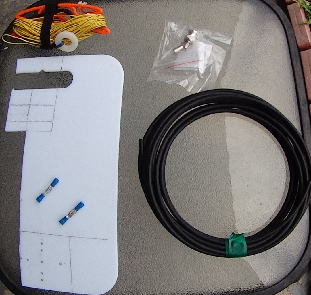


.jpg)


.jpg)


