Following on from my article about my QO-100 Satellite Ground Station Complete Build, this article goes into some detail on the Node-RED section of the build and how I put together my QO-100 Satellite Ground Station Dashboard web app.
The Node-RED project has grown organically as I used the QO-100 satellite over time. Initially this started out as a simple project to synchronise the transmit and receive VFO’s so that the SDR receiver always tracked the IC-705 transmitter.
Over time I added more and more functionality until the QO-100 Ground Station Dashboard became the beast it is today.
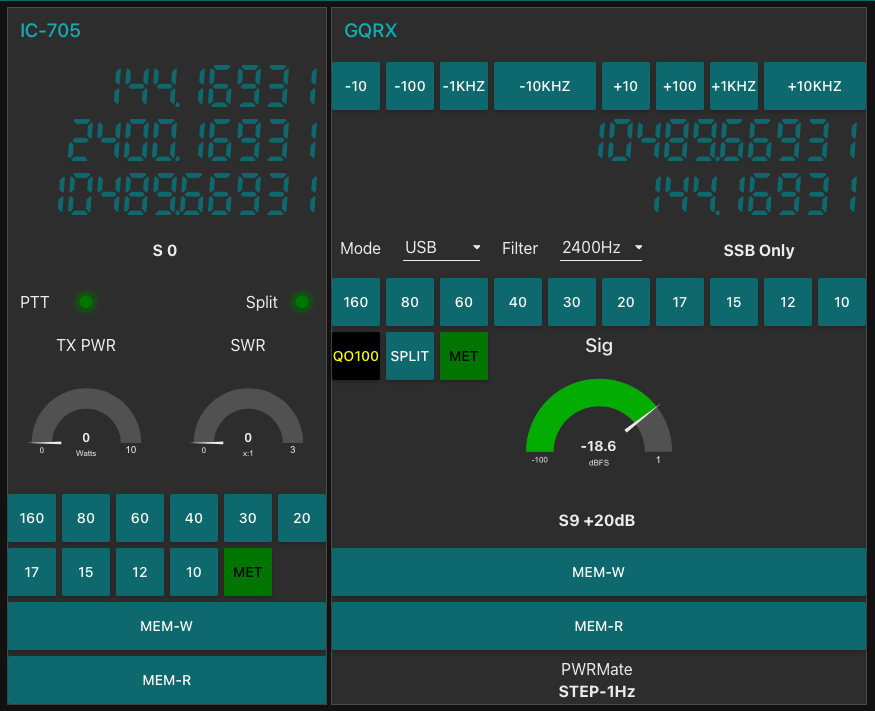
M0AWS QO-100 Ground Station Control Dashboard built using Node-RED.
Looking at the dashboard web app it looks relatively simple in that it reflects a lot of the functionality that the two radio devices already have in their own rights however, bringing this together is actually more complicated than it first appears.
Starting at the beginning I use FLRig to connect to the IC-705. The connection can be via USB or LAN/Wifi, it makes no difference. Node-RED gains CAT control of the IC-705 via XMLRPC on port 12345 to FLRig.
To control the SDR receiver I use GQRX SDR software and connect to it using RIGCTL on GQRX port 7356 from Node-RED. These two methods of connectivity work well and enables full control of the two radios.
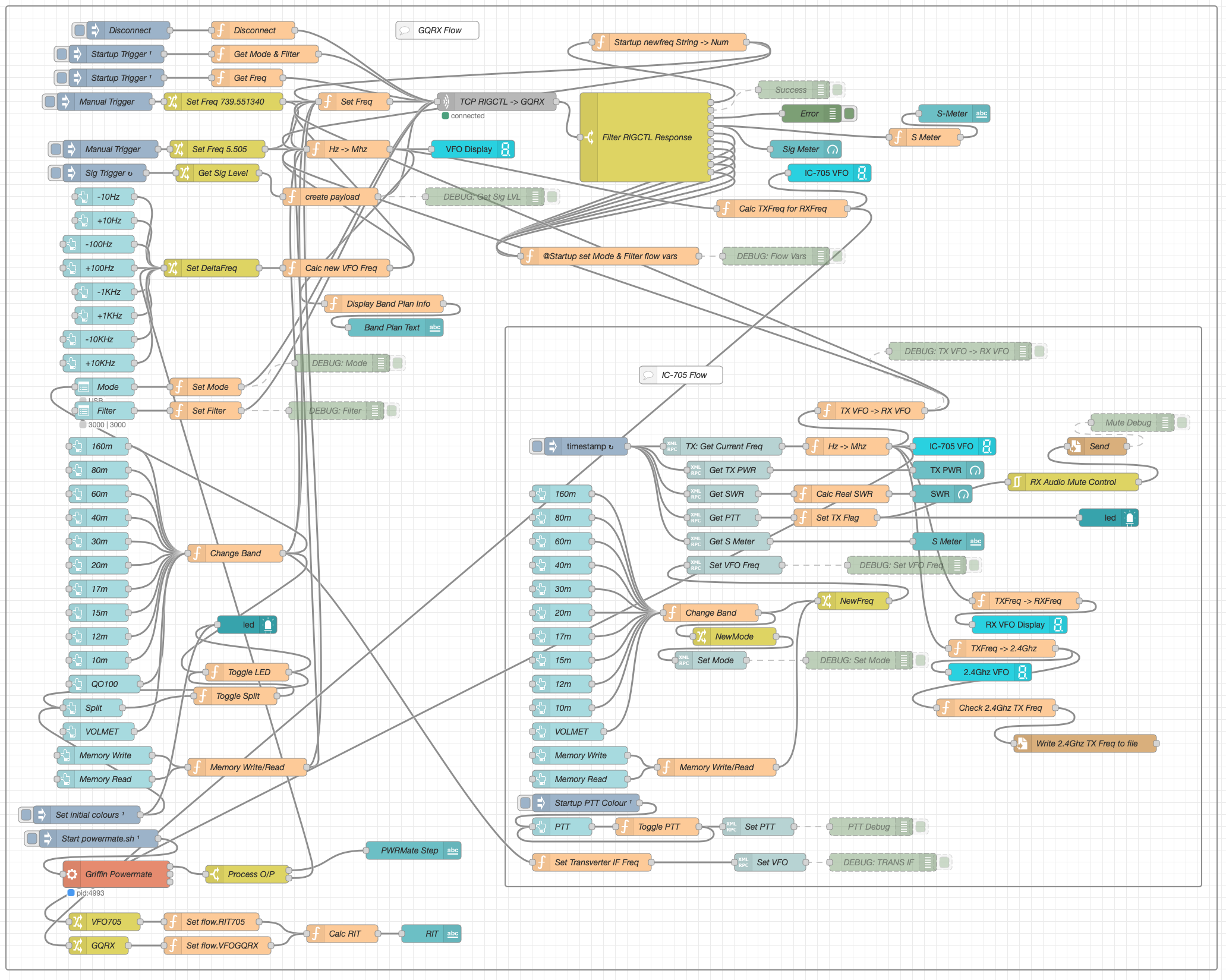
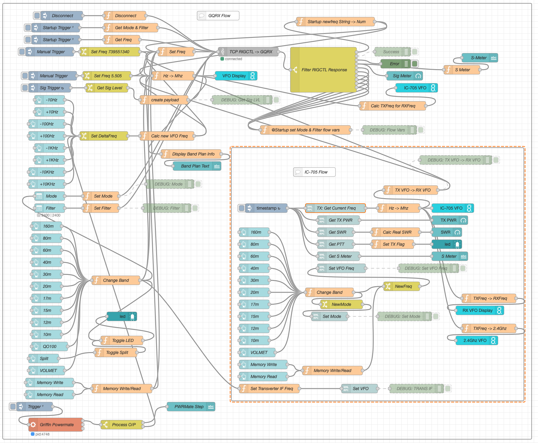
M0AWS Node-RED QO-100 Ground Station Dashboard Flow as of 12/06/24
The complete flow above looks rather daunting initially however, breaking it down into its constituent parts makes it much easier to understand.
There are two sections to the flow, the GQRX control which is the more complex of the two flows and the comparatively simple IC-705 section of the flow. These two flows could be broken down further into smaller flows and spread across multiple projects using inter-flow links however, I found it much easier from a debug point of view to have the entire flow in one Node-RED project.
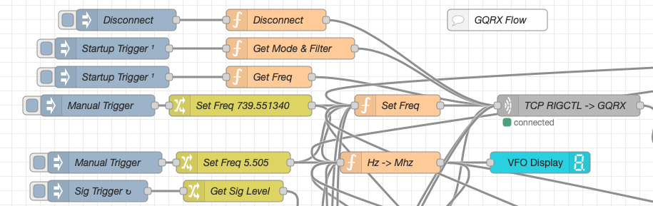
Breaking down the flow further the GQRX startup section (shown below) establishes communication with the GQRX SDR software via TCP/IP and gets the initial mode and filter settings from the SDR software. This information is then used to populate the dashboard web app.
M0AWS Node-RED QO-100 Ground Station Dashboard – GQRX Startup Flow
The startup triggers fire just once at initial startup of Node-RED so it’s important that the SDR device is plugged into the PC at boot time.
All the startup triggers feed information into the RIGCTL section of the GQRX flow. This section of the flow (shown below) passes all the commands onto the GQRX SDR software to control the SDR receiver.
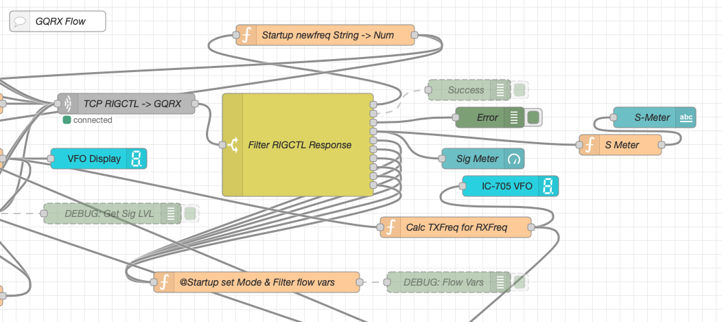
M0AWS Node-RED QO-100 Ground Station Dashboard – GQRX RIGCTL Flow
The TCP RIGCTL -> GQRX node is a standard TCP Request node that is configured to talk to the GQRX software on the defined IP Address and Port as configured in the GQRX setup. The output from this node then goes into the Filter RIGCTL Response node that processes the corresponding reply from GQRX for each message sent to it. Errors are trapped in the green Debug node and can be used for debugging.
The receive S Meter is also driven from the the output of the Filter RIGCTL Response node and passed onto the S Meter function for formatting before being passed through to the actual gauge on the dashboard.
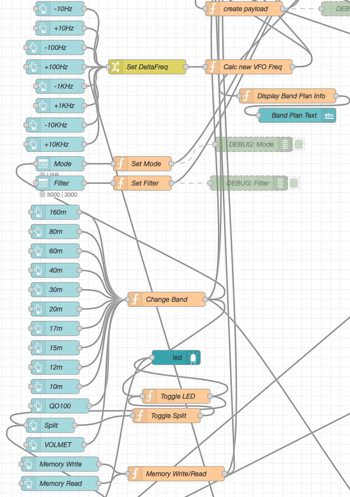
Continuing down the left hand side of the flow we move into the section where all the GQRX controls are defined.
M0AWS Node-RED QO-100 Ground Station Dashboard – GQRX Controls Flow
In this section we have the VFO step buttons that move the VFO up/down in steps of 10Hz to 10Khz. Each button press generates a value that is passed onto the Set DeltaFreq change node and then on to the Calc new VFO Freq function. From here the new VFO frequency is stored and passed onto the communications channel to send the new VFO frequency to the GQRX software.
The Mode and Filter nodes are simple drop down menus with predefined values that are used to change the mode and receive filter width of the SDR receiver.
Below are the HAM band selector buttons, each of these will use a similar process as detailed above to change the VFO frequency to a preset value on each of the HAM HF Bands.
The QO-100 button puts the transmit and receive VFO’s into synchro-mode so that the receive VFO follows the transmit VFO. It also sets the correct frequency in the 739Mhz band for the downlink from the LNB in GQRX SDR software and sets the IC-705 to the correct frequency in the 2m VHF HAM band to drive the 2.4Ghz up-converter.
The Split button allows the receive VFO to be moved away from the transmit VFO for split operation when in QO-100 mode. This allows for the receive VFO to be moved away so that you can RIT into slightly off frequency stations or to work split when working DXpedition stations.
The bottom two Memory buttons allow you to store the current receive frequency into a memory for later recall.
At the top right of this section of the flow there is a Display Band Plan Info function, this displays the band plan information for the QO-100 satellite in a small display field on the Dashboard as you tune across the transponder. Currently it only displays information for the satellite, at some point in the future I will add the necessary code to display band plan information for the HF bands too.
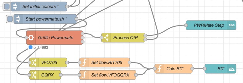
The final section of the GQRX flow (shown below) sets the initial button colours and starts the Powermate USB VFO knob flow. I’ve already written a detailed article on how this works here but, for completeness it is triggered a few seconds after startup (to allow the USB device to be found) and then starts the BASH script that is used to communicate with the USB device. The output of this is processed and passed back into the VFO control part of the flow so that the receive VFO can be manually altered when in split mode or in non-QO-100 mode.
M0AWS Node-RED QO-100 Ground Station Dashboard – Powermate VFO Flow
The bottom flows in the image above set some flow variables that are used throughout the flow and then calculates and sets the RIT value on the dashboard display.
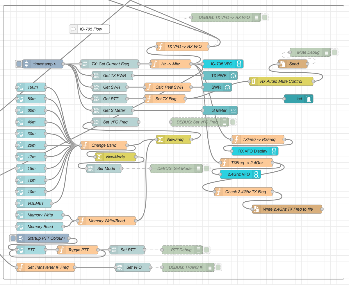
The final section of the flow is the IC-705 control flow. This is a relatively simple flow that is used to both send and receive data to/from the IC-705, process it and pass it on to the other parts of the flow as required.
M0AWS Node-RED QO-100 Ground Station Dashboard – IC-705 Control Flow
The IC-705 flow is started via the timestamp trigger at the top left. This node is nothing more than a trigger that fires every 0.5 seconds so that the dashboard display is updated in near realtime. The flow is pretty self explanatory, in that it collects the current frequency, transmit power, SWR reading, PTT on/off status and S Meter reading each time it is triggered. This information is then processed and used to keep the dashboard display up to date and to provide VFO tracking information to the GQRX receive flow.
On the left are the buttons to change band on the IC-705 along with a button to tune to the VOLEMT on the 60m band. Once again there two memory buttons to save and recall the IC-705 VFO frequency.
The Startup PTT Colour trigger node sets the PTT button to green on startup. The PTT button changes to red during transmit and is controlled via the Toggle PTT function.
At the very bottom of the flow is the set transverter IF Freq function, this sets the IC-705 to a preselected frequency in the 2m HAM band when the dashboard is switched into QO-100 mode by pressing the QO-100 button.
On the right of the flow there is a standard file write node that writes the 2.4Ghz QO-100 uplink frequency each time it changes into a file that is used by my own logging software to add the uplink frequency into my log entries automatically. (Yes I wrote my own logging software!)
The RX Audio Mute Control filter node is used to reduce the receive volume during transmit when in QO-100 full duplex mode otherwise, the operator can get tongue tied hearing their own voice 250ms after they’ve spoken coming back from the satellite. This uses the pulse audio system found on the Linux platform. The audio is reduced to a level whereby it makes it much easier to talk but, you can still hear enough of your audio to ensure that you have a good, clean signal on the satellite.
As I said at the beginning of this article, this flow has grown organically over the last 12 months and has been a fun project to put together. I’ve had many people ask me how I have created the dashboard and whether they could do the same for their ground station. The simple answer is yes, you can use this flow with any kind of radio as long as it has the ability to be controlled via CAT/USB or TCP/IP using XMLRPC or RIGCTL.
To this end I include below an export of the complete flow that can be imported into your own Node-RED flow editor. You may need to make changes to it for it to work with your radio/SDR but, it shouldn’t take too much to complete. If like me you are using an IC-705 and any kind of SDR controlled by GQRX SDR software then it’s ready to go without any changes at all.
I get quite a few emails from readers of my blog asking how my QO-100 satellite station is put together and so, I thought perhaps now is a good time to put together an article detailing the complete build.
My QO-100 satellite ground station is built around my little Icom IC-705 QRP transceiver, it’s a great little rig and is ideal for the purpose of driving a 2.4Ghz transverter/up-converter.
Of course all the software used for the project is Opensource and freely available on the internet.
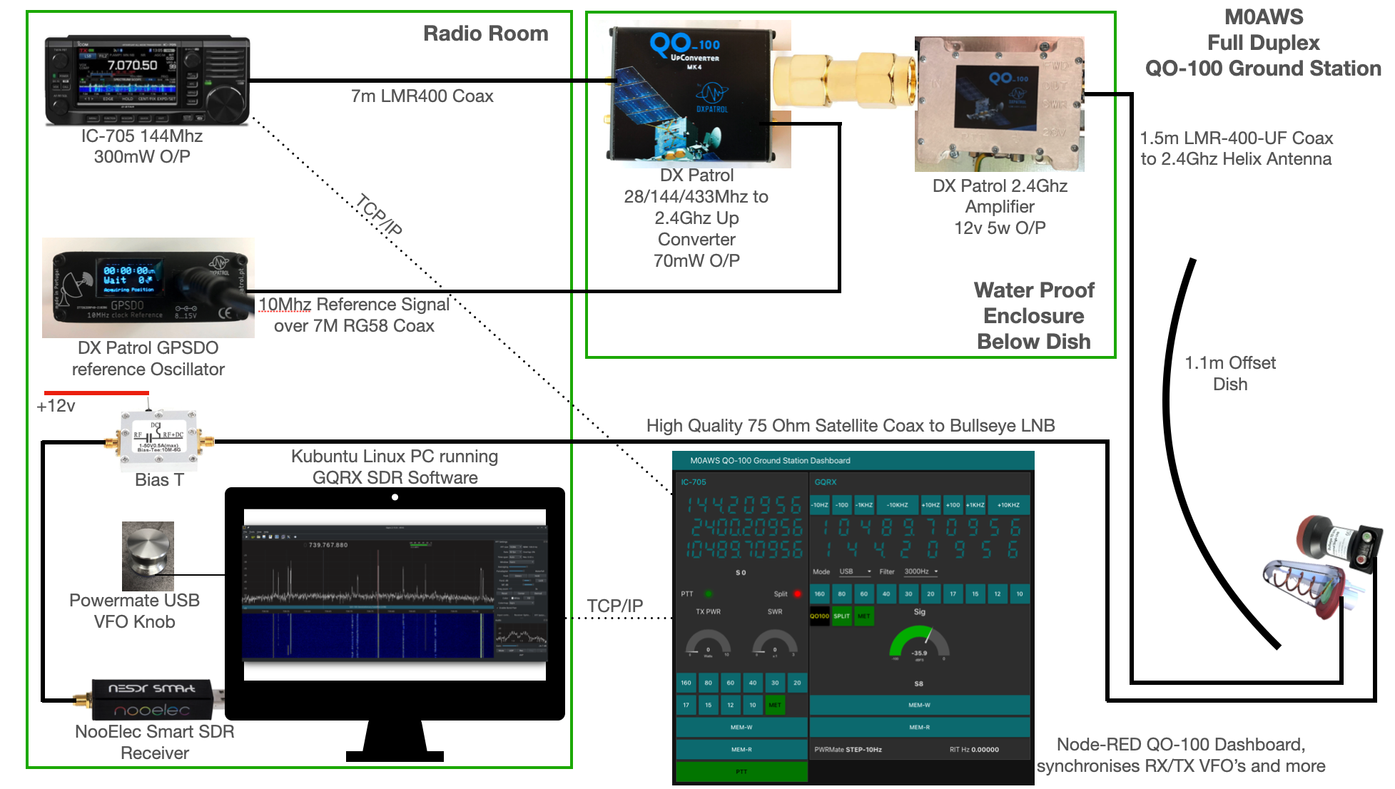
M0AWS QO-100 Ground Station Build Visual (Click to Enlarge)
The station comprises of the following building blocks:
QO-100 Ground Station Dashboard developed using Node-RED
LMR400-UF/RG58 Coax Cable
M0AWS QO-100 1.1m (110cm) off-set Dish with IceCone Helix antenna and Bullseye LNB.
To get a good clear view of the QO-100 satellite I have the dish mount 3.2m above the ground. This keeps it well clear of anyone walking past in the garden and beams the signal up at an angle of 26.2 degrees keeping well clear of neighbouring gardens.
The waterproof enclosure below the dish houses all the 2.4Ghz equipment so that the distance between the feed point and the amplifier are kept to a minimum.
The DXPatrol amplifier is spec’d to run at 28v/12w or 12v/5w, I found that running it at 28v produced too much output for the satellite and would cause the LEILA alarm on the satellite to trip constantly. Running the amp at 12v with a maximum of 5w output (average 2.5-3.5w) is more than enough for me to have a 5/9+10 signal on the transponder.
The large 1.1m dish gives me quite an advantage on receive enabling me to hear the very weak stations with ease compared to other stations.
2.4Ghz ground station enclosure ready for testing
The photo above shows the 2.4Ghz equipment mounted in the waterproof enclosure below the dish. This photo was taken during the initial build phase before I rewired it so, the amplifier is shown connected to the 28v feed. To rewire the amp to 12v was just a matter of removing the 28v converter and connecting the amp directly to the 12v feed instead. This reduced the output from a maximum of 12w down to a maximum of 5w giving a much better (considerate) level on the satellite.
It’s important to keep all interconnects as short as possible as at 2.4Ghz it is very easy to build up a lot of loss between devices.
For the connection from the IC-705 to the 2.4Ghz Up-Converter I used a 7m run of LMR-400 coax cable. The IC-705 is set to put out just 300mW on 144Mhz up to the 2.4Ghz converter and so it’s important to use a good quality coax cable.
Once again the output from the 2.4Ghz amplifier uses 1.5m of LMR-400-UF coax cable to feed up to the 2.2 turn Icecone Helix Antenna mounted on the dish. This keeps loss to a minimum and is well worth the investment.
Bullseye 10Khz High Stability Unversal Single LNB for 10.489-12.750Ghz
The receive path starts with a Bullseye LNB, this is a high gain LNB that is probably one of the best you could use for QO-100 operations. It’s fairly stable frequency wise but, does drift a little in the summer months with the high temperature changes but, overall it really is a very good LNB.
The 12v feed to the LNB is via the coax and is injected by the Bias-T device that is in the radio shack. This 12v feed powers the LNA and associated electronics in the LNB to provide a gain of 50-60dB.
Bias-T to inject 12v feed into the coax for the Bullseye LNB
From the Bias-T the coax comes down to the NooElec SmartSDR receiver. This is a really cheap SDR device (<£35 on Amazon) based on the RTL-SDR device but, it works incredibly well. I originally used a Funcube Dongle Pro+ for the receive side however, it really didn’t handle large signals very well and there was a lot of signal ghosting so, I swapped it out for the NooElec SDR and haven’t looked back since.
The NooElec SmartSDR is controlled via the excellent Opensource software GQRX SDR. I’ve been using GQRX SDR for some years now and it’s proven itself to be extremely stable and reliable with support for a good number of SDR devices.
To enhance the operation of the SDR device I have added a Griffin Powermate VFO knob to the build. This is an old USB device that I originally purchased to control my Flex3000 transceiver but, since I sold that many moons ago I decided to use it as a VFO knob in my QO-100 ground station. Details on how I got it working with the station are detailed in this blog article.
Having the need for full duplex operation on the satellite this complicates things when it comes to VFO tracking and general control of the two radios involved in the solution and so I set about creating a QO-100 Dashboard using the great Node-RED graphical programming environment to create a web app that simplifies the management of the entire setup.
M0AWS QO-100 ground Station Control Dashboard built using Node-RED.
The QO-100 Dashboard synchronises the transmit and receive VFO’s, enables split operation so that you can transmit and receive on different frequencies at the same time and a whole host of other things using very little code. Most of the functionality is created using standard Node-RED nodes. More info on Node-RED can be found on the Opensource.radio Wiki or from the menu’s above.
I’ll be publishing an article all about the QO-100 Dashboard in the very near future along with a downloadable flow file.
I’m extremely pleased with how well the ground station works and have had well in excess of 500 QSO’s on the QO-100 satellite over the last last year.
I really like Marc's (AL6JV) videos. It is great fun and very educational to watch him and his team troubleshoot some of the old gear they work on. There is also a lot of humor.
In this video Marc delves into the circuitry of the Phase-Locked Loop. I didn't know that the PLL circuitry has its origins in the space program. NASA needed a circuit that would permit very narrow band reception of a signal that was undergoing the kind of Doppler shift that spacecraft produce. Viola! Enter the PLL. Far beyond Apollo, PLL circuits started to show up in ordinary radio gear. The General Electric (and JC Penny!) CB transceivers that we rescued from 11 meter infamy used PLL as the frequency determining circuit.
Marc gives a really good explanation of how the PLL circuit works. Thanks Marc.
However, Marc gives an incorrect pronuniation of "kludge" (it should sound like fudge). But he is a computer guy and is originally from France, so all is forgiven. He also redeems himself by making fun of the inaccuracies that appear in what he calls "data shites."
Pavel CO7WT explained why Cuban hams used a process of thermal endurance to improved the frequency stability of their homebrew rigs:
--------------------
I'm CO7WT from Cuba, I started my endeavor in ham radio with a islander board.
They (FRC, like ARRL but in Cuba) made a print of a PCB to build the Islander, with component numbers and values, making construction fool proof, I think it was on the 90 or end of the 80...
Mine was built with scraps from an old KRIM 218 Russian B&W TV as Coro's explain, later on I get the 6bz6 and 6be6 tubes for the receiver (this worked better than the Russian parts) the VFO was transistorized, made with Russian components. A friend CO7CO Amaury, explain me a trick: thermal endurance:
For a week put a crust of ice on the VFO board by placing it in a frosty fridge during the night. Put them in the sun by day. This indeed improved stability, this was an old trick.
By thermal endurance I
mean improving thermal resistance vs tolerance, meaning that tolerance doesn't
vary as much with temperature changes.
It's crazy, but it
worked!!
I remember that my vfo
was on 7 MHz, with Russian kt315 as normal Russian transistors and capacitors,
nothing 1-5%, 20% at most, it ran several khz in 5-10 min, mounted on a Russian
"Formica" board (no PCB) and wired underneath.
After that treatment to
the complete board with components and everything, including the variable
capacitor; I managed to get it to "only" noticeably in the ear after
30-40 minutes.
To me it was magic!!
Basically, what I'm
describing is just "thermal annealing", but Cuban-style and with more
extreme limits.
In a refrigerator you
could easily reach -10 c and in the sun for a day in Cuba 60-80 celsius at
least.
In Cuba in the
1990s-2010s many designs of DSB radios proliferated, both direct conversion and
super heterodine (using an intermediate frequency)
At first tubes and then
transistors, mostly using salvaged parts, so it was common to find 465/500 kHz
(if common Russian) 455 khz and 10.7 Mhz with or without "wide"
filters since narrow filters for SSBs were not scarce: they were almost impossible
to get.
Not only that, crystals,
ifs, PCBs, transistors, etc.
Then, around the 2000s,
Russian 500 khz USB filters began to appear (from Polosa, Karat, etc. equipment
from companies that deregistered and switched to amateur radio) and that
contributed to improving... Even though at 7 MHz 500kc if is very close.
I made many modifications with the years mostly from 1998 to 2004 ish... better filters in front of the first RX stage (same IF described between stages) improved selectivity and out of band rejection, remember we had on that days broadcast as low as 7100 khz
Tx part was a pair of russian 6P7 (eq. RCA 807) in paralell, etc.
The Jagüey and others is
one of those evolutions...
This is something I
remember...
73 CO7WT
----------------
This is not as crazy as it sounds. We can find versions of the same technique in the writings of Roy Lewellan W7EL, Doug DeMaw W1FB, and Wes Hayward W7ZOI. I found this 2007 message from our friend Farhan VU2ESE:
I think the word 'annealing' is a bit of a misnomer. the idea is to thermally expand and contract the wiring a few times to relieve any mechanical stresses in the coil. after an extreme swing of tempuratures, the winding will be more settled. this techniques owes itself to w7EL. I first read about it in his article on the 'Optimized transceiver' pulished in 1992 or so. but all said and done, it is part of the lore. it needs a rigorous proof. - farhan
I can almost hear it, all the way from across the continent: Pete N6QW should, please, stop chuckling. Obviously these stabilization techniques are not necessary with his beloved Si5351. Some will see all this as evidence of the barbarity and backwardness of LC VFOs. But I see it as another example of lore, of art in the science of radio. (Even the FCC regs talk about "Advancing the radio art." ) This is sort of like the rules we follow for LC VFO stability: keep the frequency low, use NP0 or silver mica caps, use air core inductors, keep lead length short, and pay attention to mechanical stability. Sure, you don't have to do any of this with an Si5351. Then again, you don't have to do any of this to achieve stability in an Iphone. But there is NO SOUL in an Iphone, nor in an Si5351. Give me a Harley, a Colpitts, or a Pierce any day. But as I try to remember, this is a hobby. Some people like digital VFOs. "To each, his own."
Above you can see what I picked up at the Vienna Wireless Society's 2024 Winterfest Hamfest.
-- On the left in the blue box is an MXM Industries SuperRX/TX 40 transceiver. It is a kit from a Texas company. Superhet receiver with IF at 455 kHz. Crystal controlled CW transmitter on 7040 kHz. The oscillator works, but so far no receive signals. I will have to troubleshoot. Does anyone have a schematic?
-- Behind the MXM there is a nice box marked "Diode Detector" I opened it up and there is just a solid state diode and a 50 ohm resistor to ground. Box may be useful.
-- I got a couple of books: "Weekend Projects" 1979 from ARRL, and "A History of QST -- Volume 1 Amateur Radio Technology 1915 - 2013" 2013 from ARRL.
-- On top of the Weekend Projects book you see a "Crystal Holder" from Gross Radio of New York City. W1UJR has some good history on this company: https://w1ujr.com/written-word/gross-radio-company-circa-1931/ This device seem to be intended to hold in place a raw piece of quartz! Cool.
-- To the right of the books there is a serious-looking VFO. One dollar! Deal! It is a CB VFO, but the markings say it puts out 5.44 to 5.99 MHz. So it should be useful. The dual speed dial is very nice.
-- Above the VFO is a nice step attenuator from the "Arrow Antenna" company of Loveland Colorado.
-- Further to the right are some Electric Radio and Antique Wireless Association magazines that Armand WA1UQO gave me. Really nice. The AWA mags have a very thoughtful piece (warts and all) on Jean Shepherd. And the ER pile has an article by Scott WA9WFA that mentions my work on the Mate for the Mighty Midget receiver. Thanks again Armand!
-- I also got some ADE6+ surface mount mixers. The price was right!
Above — This blog post supports the video shown above
[1] SIGNAL GENERATOR
Steve AA7U & Everett N4CY, built gear -- plus a procedure to test Intermodulation Distortion (IMD) on a loop amplifier using a Siglent SDG2042X generator and SSA3021X spectrum analyzer. Click on this hyperlink to read about it. I'm a fan of Siglent test equipment.
My strategy employs a 50.0 MHz crystal oscillator-based signal generator plus a 50.1 MHz VFO as the second signal source. My VFO tunes from about 49.6 to 51.8 MHz via a front panel air variable capacitor.
My 50.1 MHz VFO
Above — VFO schematic. Although I had worked out the low-pass filter L and C values, I built this VFO without a schematic and perhaps would build it differently if I needed to make another. I might consider tuning the output of the differential amplifier buffer for more output power and less harmonic energy.
I thought mostly about temperature drift when making this -- I started with JFET amp as the oscillator and struggled to make it work. This would be wise since a JFET offers better temperature drift over a BJT and gives a cleaner output signal with lower phase noise. However, I only had 1 day for this entire project and got frustrated. I deployed a common base PNP BJT local oscillator (LO) that never fails for me.
Both the LO and its buffer get regulated, well filtered DC. The LO gets temperature compensation/separation from the 8.2 volt Zener diode-based voltage regulator by way of 2 R C low-pass filters. I applied several C0G caps to resonate the tank and ran 2 air variable trimmer capacitors -- 1 as the main board frequency trimmer, the other as the front panel tuning control.
The LO gets lightly coupled via 1 pF to a differential amplifier emitter fed 10 mA with a current source. Differential amps offer strong reverse isolation, plus a reduced 2nd harmonic if the BJT balance is OK. The BC546 pair offer reasonable balance right out of the bin (without matching) & the BC546C serves as my go-to differential amp BJT from DC to ~ 100 MHz. The 10 mA current source, plus the 21 mA current in the final feedback amp provide heat for my temperature compensation scheme.
Low-pass filters built using T30-10 toroids worked OK. This was a board cram -- so the inductors are not spaced apart as much as when more board space is available. The 22 gauge air inductor measured ~ 374 nH & seems well anchored to the main 1-sided board with J-B Weld epoxy, plus the grounded coil lead soldered to the main board. The main board = 1/16″ (1.60 mm) Half Ounce 500 Series Copper Clad Board from MG Chemicals.
Above — Copper board under test. To simulate the front panel capacitor, I've got the air variable front panel tuning cap in a small bracket that I got from a local Builders merchant. I have several for holding caps, jacks and potentiometers during test phase circuit development. Mine are all pre-drilled with the proper sized holes to fit pots jacks, or air-variable trimmer caps.
Above — Close up of the tank coil secured with a messy application of epoxy.
Above — Side view. The actual front panel capacitor leads were this long to allow slack to put on the herring tin cover. The Herring Tin lid added much difficulty with temperature compensation and construction tactics -- but I got it done! The idea of the herring tin cover came from this blog post
Above —View for the VFO showing the DC input port ( an RCA connector ) plus the SMA RF output port. 2 bolts hold the tin to the copper clad board.
Above — My 50.0 MHz xtal based oscillator next to the Herring made VFO. Ready for 2 tone testing. The front panel tuning capacitor is front left. The front panel bolt just fills in a hole I drilled by mistake.
If I want to drive a DUT such as a high IP3 amp -- or say a diode ring mixer ( I rarely use them anymore), I'll chain up 1 of 3 separate, sealed up wide band amplifiers that range from 12 dB to 26 dB gain (up to 150 MHz or so). I also have a plethora of low-pass and band-pass filters in sealed Hammond cases that go from 5 MHz to microwave if needed.
[2] 6 dB HYBRID COMBINER
Above — The VHF targeted hybrid combiner is also a return loss bridge and vice versa. No experimenter bench should likely be without a return loss bridge or 3. I built with standard 1/4 watt 1% metal film resistors and tried several different coils as the transformer. After many versions, I settled with 3 stacked BN61-2402 ferrites with 4 total turns of lightly twisted wire. I twisted the wires only enough so they would stay together during winding. Because of only 4 turns, I was able to use 28 gauge wire. I measured 43 dB port isolation at 50 MHz.
Above — The applied transformer.
Above — Boxed up combiner/return loss bridge with a Mini-Circuits Lab 50 Ω SMA resistive load attached.
Above — Another view of the hybrid coupler
Above — My favourite design project of 2014: a wide band return loss bridge with directivity >= 30 dB from 5 MHz to 1.5 GHz. You may read more about it in the old site pops.net archive: Topics 2012 - 2014 : Caitlyn 310 — UHF Beginnings : 3. Return Loss Bridge Experiments : Bridge #4
I’ve been making a few improvements to my QO-100 Node Red Dashboard whilst waiting for the 2.4Ghz hardware to arrive. I’ve added the ability to split the RX and TX VFOs so that I can tune away from the TX frequency for working split stations or for tuning to slightly off frequency stations. I also added a series of tuning buttons to the top of the GQRX side of the dashboard to enable easy tuning using the trackball connected to my Kubuntu PC. This worked well but, I really missed having a real VFO knob like a conventional radio.
As I had a Griffin Powewrmate USB VFO from a previous SDR radio I added it to the flow as well so that I had a physical VFO knob for the SDR receiver. Details on how I got it working using evtest and a simple BASH script are in the Griffin Powermate article.
M0AWS QO-100 Node Red Dashboard Flow
The Node Red flow is looking a little busier with the addition of split mode and the Griffin Powermate USB VFO which has really enhanced the useability of the solution. It’s very impressive what can be achieved with Node Red with a little imagination. You really don’t need to be a heavy weight programmer to make things work.
M0AWS QO-100 Node Red Dashboard as of 07/06/23
I also put together some code to calculate the S Meter reading from the dBFS data the GQRX SDR software generates. It’s not 100% accurate but, it’s close enough to be useful.
On the IC-705 side of the Dashboard I also now display the 2.4Ghz uplink frequency so that it’s available for logging.
So with the QO-100 Dashboard ready to go live I have now started putting together the 2.4Ghz transmit path of the ground station. I have the 2.4Ghz transverter and matching 12w amplifier from DXPatrol, the IceCone Helix 2.4Ghz antenna from Nolle Engineering, some LMR-400-UF and connectors from Barenco and an appropriate water proof enclosure from Screwfix to fit all the kit into however, I’m now being held up by one simple little SMA male to SMA male connector that I need to connect the transverter and amp together.
M0AWS Waterproof enclosure from ScrewfixM0AWS Laying out the 2.4Ghz TX kit in the enclosureM0AWS LMR-400-UF coax from Barenco
The SMA connector has been ordered but, is taking a month of Sundays to arrive! Hopefully it’ll arrive soon and I’ll finally get on the QO-100 satellite and start enjoying the fun.
I’ve been gradually building my QO-100 ground station over the last few months and have had the receive path working for some time now. One of the things I really miss with the Funcube Dongle Pro+ (FCD) SDR is a real VFO knob for changing frequency.
My QO-100 Node Red dashboard is configured so that I can have the FCD track the uplink frequency from the IC-705 but, sometimes I use the FCD without the IC-705 in the shack and so a physical VFO would be handy.
Many years ago when I lived in France (F5VKM) I had a Flexradio Flex-3000 SDR, a great radio in it’s time and one that gave me many hours of enjoyment. One addition I bought for that station was a Griffin Technology Powermate VFO knob. It worked extremely well with the PowerSDR software for the Flex-3000 and I used it for many years.
Many years later I’m back in the UK and much of my equipment is packed away in the attic, including the Griffin Technology Powermate VFO.
I decided to dig it out and see if I could get it working with GQRX SDR software. Sadly I couldn’t get it working with GQRX however, I did find a way of getting it working with Node Red and thus could add it to my QO-100 Node Red Dashboard and then control GQRX with it via a simple Node Red flow.
Griffin Technology Powermate VFO
Plugging the Powermate VFO into my Kubuntu PC it wasn’t immediately recognised by the Linux O/S. After a little searching I found the driver on Github. I added the PPA to my aptitude sources and installed the driver using apt.
Once installed the default config for the Powermate device is to control the default audio device volume. To make the device available for use as a VFO knob you need to change the configuration so that the default setting is disabled. To do this is relatively easy, just edit the config file using your favourite command line editor (Vi/Vim in my case) and add the following entry.
vi /etc/powermate.toml

# Entry to control HDMI volume with Powermate
#sink_name = "alsa_output.pci-0000_01_00.1.hdmi-stereo"

# Set powermate not to work with volume control
sink_name = ""
As shown above, comment out the default “sink_name” entry (Yours may be different depending on audio device in your PC) and add in the Powermate “sink_name” entry that effectively assigns it to nothing.
Once this is done, save the file and exit your editor and then reboot the PC.
Next you’ll need to install a small program called evtest.
sudo apt install evtest
To check the evtest program has installed correctly, plugin your Powermate VFO to any available USB port and run the following command in a terminal.
evtest /dev/input/powermate
Turning the Powermate knob you should see output on the screen showing the input from the device. You should also see BTN events for each press of the Powermate device.
Input driver version is 1.0.1
Input device ID: bus 0x3 vendor 0x77d product 0x410 version 0x400
Input device name: "Griffin PowerMate"
Supported events:
  Event type 0 (EV_SYN)
  Event type 1 (EV_KEY)
    Event code 256 (BTN_0)
  Event type 2 (EV_REL)
    Event code 7 (REL_DIAL)
  Event type 4 (EV_MSC)
    Event code 1 (MSC_PULSELED)
Properties:
Testing ... (interrupt to exit)
Event: time 1685816662.086666, type 2 (EV_REL), code 7 (REL_DIAL), value -1
Event: time 1685816662.086666, -------------- SYN_REPORT ------------
Event: time 1685816662.318638, type 2 (EV_REL), code 7 (REL_DIAL), value -1
Event: time 1685816662.318638, -------------- SYN_REPORT ------------
Event: time 1685816662.574615, type 2 (EV_REL), code 7 (REL_DIAL), value -1
Event: time 1685816662.574615, -------------- SYN_REPORT ------------
Event: time 1685816663.670461, type 2 (EV_REL), code 7 (REL_DIAL), value 1
Event: time 1685816663.670461, -------------- SYN_REPORT ------------
Event: time 1685816664.030421, type 2 (EV_REL), code 7 (REL_DIAL), value 1
Event: time 1685816664.030421, -------------- SYN_REPORT ------------
Event: time 1685816664.334389, type 2 (EV_REL), code 7 (REL_DIAL), value 1
Event: time 1685816664.334389, -------------- SYN_REPORT ------------
Event: time 1685816665.334255, type 1 (EV_KEY), code 256 (BTN_0), value 1
Event: time 1685816665.334255, -------------- SYN_REPORT ------------
Event: time 1685816665.558230, type 1 (EV_KEY), code 256 (BTN_0), value 0
Event: time 1685816665.558230, -------------- SYN_REPORT ------------
Event: time 1685816666.030161, type 1 (EV_KEY), code 256 (BTN_0), value 1
Event: time 1685816666.030161, -------------- SYN_REPORT ------------
Event: time 1685816666.182151, type 1 (EV_KEY), code 256 (BTN_0), value 0
Event: time 1685816666.182151, -------------- SYN_REPORT ------------
At this point you’re ready to stop evtest (CTRL-C) and then create the following little BASH shell script that Node Red will run to collect the O/P from the Powermate USB device.
#!/bin/bash

###############################################
# Griffin Technology Powermate control script #
# for Node Red.                               #
#                                             #
# 04/06/23 - M0AWS - v0.1                     #
#                                             #
###############################################

VAL="1"
echo "STEP-1Hz"

/usr/bin/evtest /dev/input/powermate | while read LINE
do
   case $LINE in

      *"(REL_DIAL), value 1") echo "$VAL"
           ;;

      *"(REL_DIAL), value -1") echo "-$VAL"
           ;;

      *"(BTN_0), value 1") case $VAL in

                              "1") VAL="10"
                                   echo "STEP-10Hz"
                                      ;;

                             "10") VAL="100"
                                   echo "STEP-100Hz"
                                      ;;

                             "100") VAL="1000"
                                    echo "STEP-1Khz"
                                       ;;

                             "1000") VAL="10000"
                                     echo "STEP-10Khz"
                                         ;;

                             "10000") VAL="1"
                                       echo "STEP-1Hz"
                                          ;;
                              esac
                                 ;;
        esac
done
Once the BASH script is copied and pasted into a file called powermate.sh you need to make it executable by using the following command.
chmod 700 ./powermate.sh
If you now run the shell script in a terminal you’ll see a similar output to that shown below from the device when used.
As you can see above the shell script outputs a positive or negative number for VFO tuning and changes the VFO step size each time the Powermate is depressed.
Getting this output from the BASH shell script into Node Red is really simple to achieve using just 3 or 4 nodes.
In the Node Red development UI create the following nodes.
Griffin Powermate Node Red Nodes
The first node in the flow is a simple inject node, here I called it trigger. This sends a timestamp into the next node in the flow at startup to set the flow running.
The Griffin Powermate node is a simple exec node that runs the script we created above.
M0AWS Powermate exec node
Configure the node as shown above and connect it to the inject node that’s used as a trigger. Note: Change “user” in the Command field shown above to that of your username on your Linux PC)
Once done create the third node in the flow, a simple switch node and configure as shown below.
Switch Node for Powermate
The switch node has two outputs, the top one is a text output that is fed into a text field to show the current step size of the Powermate device and the lower output is the numeric output that must be fed into your VFO control flow so that the VFO value is incremented/decremented by the amount output by the Powermate device.
I’ve found the Griffin Technology Powermate USB device works extremely well with Node Red and GQRX that I use for controlling the FCD SDR radio and it’s now part of my QO-100 ground station build.
M0AWS QO-100 Dashboard with Powermate Step Display at bottom
As shown above you can see the Powermate Step size at the bottom of the dashboard, this text changes each time the Powermate device is depressed and will set a step size of 1Hz, 10Hz, 100Hz, 1Khz, 10Khz in a round-robin fashion.
The next stage of the build is the 2.4Ghz transmit path. I now have all the necessary hardware and so this part of the build can finally commence.
To many, this will be just another Si5351 VFO project, with nothing to distinguish it from the others. In fact, that’s exactly what it is. The “how to” of connecting an Arduino board to an Si5351 board, wiring up a display, and loading the firmware, is straightforward, and well established. To me though, it was a complete mystery. I have been very adept, my whole life, at studiously avoiding anything to do with digital electronics, computing, coding, and the like. When my friends in school were getting excited over Sinclair ZX81’s, BBC Micros, and Commodore 64’s, I was building a one-tube regen, an 80M DSB transceiver, listening to my British military R107 shortwave receiver, and talking to hams on the local repeater on my converted Pye tube VHF base station. I remember wandering into a Tandy store (what us Brits called Radio Shack) in the city of Worcester at some point in the late 70’s, and being greeted by the sight of a Tandy computer – probably a TRS-80 or something similar.
“What does it do?” I asked the salesperson.
“What do you want it to do?” he replied.
This seemed like a strangely non-committal response. Maybe he didn’t know what it did, and was merely throwing the responsibility for finding out back on me? I don’t remember anything about him now, but perhaps he was some gangly teenager who knew little about the stuff he sold, and whose main thought was getting off work so he could go to the pub with his friends? That’s it! He was just trying to appear knowledgeable by giving me a non-answer! This suspicious reaction was quite representative of the way I thought about computers back then. Just as it’s hard, if not impossible, to get the measure of a person if they willfully refuse to reveal anything of themselves to others, so it seemed with computers. These expensive boxes just sat there, doing nothing, except waiting for instructions. Such a disappointing lack of character! How is one supposed to respect a person or an object that sits quietly in a corner, waiting to be told what do? How feckless! Dedicated hardware, however, was different. When you bought a radio receiver, you knew that, on twiddling a few knobs and flicking a few switches, it would receive radio signals. A burglar alarm would alert you to the presence of burglars (well in theory, anyway), and those remote control cars that RS sold by the gazillion were guaranteed to quietly drive your family nuts in the days after Christmas before work, and school, resumed. Computers, on the other hand, promised everything but actually did nothing, until you told them what to do – and even then, there were a myriad of ways in which they could obstinately refuse to comply with your wishes. Not for me!
And so it was that, throughout my adult years, I deprived myself of exposure to things digital. I am not proud of my incurious nature about many things – though, when I am interested in something, I exhaust myself with the sheer intensity of focus. It’s an odd type of blinkered approach to the world that leaves others confused. I can’t say I blame them. The projects I built ran off anything from a few volts, up to 15-20V or even more. 9V batteries worked fine (we called ’em PP3’s), as did the old 12V lead acid battery that would no longer power the family lawn mower, but did a sterling job of powering the radio gear in my bedroom. My circuits weren’t picky about voltage, but these new-fangled digital chips just wanted to see 5V. Really? What kind of a voltage was that? They came with a surfeit of incomprehensible nomenclature too. Words that sounded like something John Lennon would have made up for a song post-1965. Words like NAND. You know, it wasn’t so much that this stuff wasn’t interesting – it was simply that I was really into building little radio receivers, and didn’t see how this digital stuff could help me (I wasn’t very imaginative). I had a small stash of ferrite rods, variable capacitors, resistors, and transistors, and some 9V battery snaps and with that, I had all that I needed. These were the days when loading a program onto a computer meant playing an audio cassette into the “line in” jack of your computer. I just didn’t see how any of that world full of DOS, NAND gates, tiny amounts of RAM, and the like, as well as really weird voltages like 5V, could possibly apply to me. Yes – I was that closed-minded. It’s not hard to see how a few years later, when we all graduated from University, my colleagues went on to successful careers with big technology companies, designing integrated circuits, and building the backbone of the internet, while I moved to Los Angeles and promptly became a DJ
A few years ago, a friend generously gifted me a Bare Bones Arduino board. I didn’t know what it was. It had header pins sticking out of it but, at that point, I didn’t really know what header pins were, or how to connect to them. I looked at it, and wondered what to do with it. What did it do? How did it do it? What was I supposed to connect to it? I placed it carefully in a box along with some other electronic things that confused my simplistic analog mind, and carried on with my life. Every now and again, I’d take it out of the box, blink at it a few times, and put it back. I knew that Arduino was the new big thing, and something that was going to play a big part in ham radio homebrewing in the coming years but I guess that, with my toroids and air-spaced variable capacitors, I wasn’t ready for it yet. Not that my experience level in this arena was completely non-existent. I had taken part in the beta tests of the Etherkit CC-20 and later, the planned CC1 series of QRP transceivers. These experiences had taught me that I could solder SMT devices, and even replace an SMT ATMega328P with nothing more than a soldering iron, soldering wick, flux, and a sharp blade. It was a small revelation to learn that I could do this stuff. Jason NT7S very patiently walked me through the process of flashing the firmware onto the ATMega328 via the ICSP header mounted on the board. This was a first for me, and quite exciting to gain a new skill, which proved handy when I built the SPT “Sproutie” Beacon, and needed to flash firmware onto the ATtiny13 in that little transmitter.
Then, recently, I took the Bare Bones Arduino board out of the box which had been it’s home for a few years and, this time, something clicked. “Goshdarnit” I thought, “I’m going to make an LED blink. If others can do it, so can I!
You can’t see the LED blinking in the above photo. The fact that the board is not powered doesn’t help, but take it from me that when it was powered, it was blinking!
I spent a few days and nights with the LED blinking and pulsating at various rates, as I loaded different sketches, and adjusted the parameters. As fun as flashing lights are to a simple lad like me, it wasn’t the reason I wanted to resurrect this little Arduino board from it’s relaxing life in storage. I had an Etherkit Si5351 Breakout Board that needed to have life breathed into it. I wanted to generate RF, by golly!
This next stage was where things started to come into focus, and it began to dawn on me that using one of these little breakout boards to generate a stable RF signal wasn’t all that hard at all – well, from the point of view of the end user, at least. Once I did a bit of reading up on how to control the Si5351, I was just a little gobsmacked. You mean all it needs in terms of data input is 2 connections? SDA (serial data) and SCL (serial clock)? That’s it? I made those 2 connections between the Arduino and Si5351 board, uploaded the Etherkit Si5351 example sketch, and almost fell off my chair when the Si5351 began emitting RF on the frequency I had entered into the sketch just before uploading it. It was a moment of realization – that this little board actually was a programmable oscillator. How incredibly neat! No more custom-cut crystals – for ~$10, you can get a board like this, and program it to the frequency of your desire (within it’s specified limits), and it replaces both the crystal and the oscillator. For a single frequency, once you have programmed it, it doesn’t even need a micro-controller connected to it. Fantastic!
I suppose that was the moment at which my mind, which moves at the speed of molasses, “got” that a VFO with this board is really a micro-controller which, with the help of a rotary encoder, is re-programming the Si5351 “in real time” as the encoder knob is turned. Every single click of the encoder sends a new instruction to the Si5351, to step up or down, in an increment which the firmware has already specified. I was hot to trot, so began looking around for a basic Si5351 sketch. The word “sketch” reminds me of the Etch-A-Sketch which I never came close to mastering as a child. I must admit that I think this association slightly trivializes Arduino programs (which are written in a type of C) in my mind, but that is what they are called, so that is what I will call them.
What I was looking for was a sketch that would allow me to vary the frequency of the Etherkit Breakout Board continuously in the HF region, from at least 3 – 30MHz. I was only concerned with one of the 3 clock outputs. At this point, I simply wanted to use it as an HF signal generator for testing purposes, or to control a general coverage direct conversion receiver. Perhaps at some point, I’ll begin fiddling around with code, and learning how to modify it for my own purposes, but at this point, I wanted a sketch that I could upload to the programmer, and immediately be in business. I also wanted to use one of those tiny little OLED displays, due to the enclosure I was considering. This was the point at which I found Thomas LA3PNA’s sketch entitled, “A simple VFO for the Si5351 for either LCD or OLED.” Perfect!
This was also the point at which I discovered that the ATMega168 in my little Arduino clone board didn’t have enough memory to hold Thomas’ VFO sketch. I considered purchasing a newer Arduino board or clone, but most of the ones I saw had more stuff on them than I needed or wanted, in terms of inputs/outputs and programming ability. All I wanted was the ATMega328P, and a 6-pin ICSP header to program it with. Then I remembered back to my time working on the Etherkit CC-20 beta, and how I had expertly fried the micro-controller. Jason sent me a replacement and, wisely, included a few extras, in case my prowess at destroying delicate chips were to reassert itself. I still had those little SMT ATMega328P’s lying around, as well as a supply of breakout boards to mount them on. Problem solved! Building something from parts on hand is so much more satisfying than purchasing a ready-made solution – at least, for the first time, it is.
I sat down to scribble out a schematic, and it was during this process that the realization hit, as to what an Arduino board is. What makes Arduino, well, Arduino, is not the board, but the software platform that supports it. Apologies for stating what is well known fact to many readers, but this had all been previously unknown to me. The board itself is really just a micro-controller, with the power supply and input/output options either suited to the tasks at hand or, in the case of a larger and more general purpose board, such as the Uno, many different such options, to make it as versatile as possible. Ths was fantastic, because what it meant was that all I needed to control the Si5351, was a micro-controller (ATMega328P), a 16MHz crystal with the two associated capacitors, a 5V power supply, and some 0.1uF capacitors for bypassing. Oh – and a 6-pin header for programming. The schematic for the VFO is simple because, as far as the hardware goes, everything happens inside the micro-controller and the the Si5351 (which are both internally complex). The rest of it happens in the firmware. As far as hardware goes, we’re simply tasked with the 21st century equivalent of assembling a crystal set.
Here’s what I came up with. There are an awful lot of unused pins but, for this purpose, there are a lot of pins we don’t need. Without thinking, I was about to connect the AREF pin to +5V, because that’s what I was seeing in the various schematics I was using as references, until it occurred to me what AREF stands for. It’s an Analog REFerence pin. This application uses only digital inputs and outputs, so figuring that I didn’t need an analog reference, I didn’t connect it –
Although not shown in this schematic, the encoder pushbutton for setting the tuning rate goes to digital pin 11 (pin 15 of this TQFP package). Also, the CLK outputs of the Si5351 don’t like DC voltage being applied. I fried one of these chips by accidentally applying 13.8V DC to the CLK 0 output. As a safeguard, it would be a good idea to permanently attach a coupling capacitor to the CLK 0 output of the Si5351. After my accident, I used as 0.1uF capacitor on mine. Some projects might require looser coupling, but you can always put a lower value capacitor in series with the output of this VFO to achieve this objective.
While planning this little VFO, a number of questions were presenting themselves to me. The main one concerned the issue of both the Si5351 Breakout Board and the OLED display being connected to exactly the same SDA and SCL connections. The I2C protocol does allow for multiple devices on the same line, but my understanding was that if more than one device is employed, then the firmware needs to include the unique address of each device. Would Thomas’ sketch work from the get-go, I wondered? As it happened, it did and, as of writing this, I don’t know if this is because
a) the address of the OLED was included in the library definition for this little display, or
b) with a setup like this that only has 2 devices connected, the instructions for the OLED are ignored by the Si5351, and vice-versa.
I’d like to be able to describe the exact steps I took when setting up the sketch, but I have, lamentably, forgotten them. I do remember installing the UG8lib library in the Arduino IDE, which supports the commonly available OLED displays. I also remember, at some point, uncommenting a line that specifically refers to devices that have an SSD1306 driver chip. If you purchase a cheap monochrome 128 x 64 OLED, this is probably the driver chip your display will have. These little displays are available for <$3 including shipping. Deal!
Here’s the ATMega328P mounted on the breakout board –
The controller part of the circuit constructed, with it’s supporting components. No power supply yet, as during initial testing, it will be powered through the ICSP header –
And with the Etherkit Si5351 Breakout Board fitted. The I2C control lines and 5V supply line are connected underneath the Etherkit board –
It took a while to figure out how to mount the OLED to the front panel. The 4 mounting holes are sized for #2 screws. I thought of running 4 #2 screws from the front panel, straight through to the OLED, and spacing the display away from the panel with 4 #2 nuts. The nuts were so close to the glass covering the display though, that they could have cracked it while being tightened. In retrospect, stacked #2 washers might have worked, though long before thinking of that, I came up with this rather more complex solution. It involved a small piece of PCB material, drilled and cut to size. #2 shakeproof washers and 3/16″ x 3/16″ nylon spacers were also employed. Their use should be apparent in subsequent photos –
I seriously considered fabricating a PCB enclosure for this little VFO, even getting as far as cutting some of the main pieces. The primary reason for wanting to use a custom enclosure was that the other case I was considering (which I ended up using) was a little too high. As a result, the front panel had, in my opinion, too much empty space. A PCB enclosure, about 4″ x 4″ x 1.5″ high would have looked mighty spiffy. However, I didn’t have the mettle to go through with it. I just couldn’t get quite inspired enough to put all that extra work into making a custom enclosure, and fell back on my favorite ready-made enclosure, the 143 from LMB Heeger. It is 4″ x 4″ x 2″ high, and available in plain aluminum finish, smooth light grey paint, or a sort of wrinkled black finish. They are also available with either an undrilled cover, or a perforated cover. The encoder was connected using header. The main reason for this was that I wasn’t sure if the cheap Chinese encoder ($1.68 each, inc shipping) was up to the task, so wanted to facilitate easy replacement –
A close-up, showing a little more detail of the mounting of the OLED to the front panel. Like the encoder, the display was also connected using header, making installation, and any dismantling for repair or upgrade purposes, easier –
Amazingly, it worked!
With the perforated cover you could, if you wanted, add some internal LED’s, for a splash of light to brighten up the shack, and add some flair. Being frugal energy-wise, I left the LED’s out for the time being. As it stands, the VFO already consumes 86mA at ~12V, which is not an insignificant amount –
Although the hardware side of this little project is finished (or very close to it), I am still very much fiddling with the firmware. As well as using Thomas’ code, I have been trying out sketches from other folk too. I began by trying to find a sketch that would do exactly what I wanted it to do, and fast discovered that, at the very least, an ability to modify code was required. That lesson led to a desire to actually develop a more complete understanding of C, so that I can at least do intelligent re-writes, if not write my own from scratch. This is all a bit overwhelming, and I vacillate from having fun, to being very grumpy, and back again
Thank you Thomas LA3PNA for the sketch – and also to the many others whose code I have been borrowing, and will no doubt butcher. I view this little VFO very much as a learning platform, from a programming point of view. Also, a big thank you to Jason NT7S for the Etherkit Si5351 Breakout Board, and the very useful libraries, which are seeing much use from homebrewing hams.
PS – I just started reading “Beginning C For Arduino” by Jack Purdum. Great stuff.
UPDATE (Jan 30th 2021) – I made a few small changes to the sketch, to improve the display a little. I found a font to display the frequency, that is a little larger. It is in the U8G library, and is known as helvB18. I also removed the word “step” from in front of the step size, as I felt it was self-explanatory. The text needed to be moved around on the display a little to fit it in, and this was adjusted in the sketch.
Since building this little clock generator, I noticed that, although the sketch set the Si5351 to start up on 7030KHz, it would nearly always start up 100Hz higher. Unsure whether this is a software or hardware issue, I did the clumsy workaround of altering the sketch to start up on 7029.9KHz. As a result, it now starts up on 7030KHz. I’d like to find the reason for this discrepancy, and fix it at the source.
I also added a 5mm red LED inside the case, with a 1K resistor in series with the +ve lead, connected to the 12V DC power connector on the back. The LED lights up the whole inside of the case, though this is not so obvious in the daylight shot below –
However, when used indoors, the red light is visible through all the perforations in the case, and looks great. It’s almost reminiscent of the old tube days. The red light effect actually looks a bit better in real life than in the photo. This Si5351 VFO/signal generator draws 105mA, of which 10mA is the LED –
Although I’ve had quite a few thoughts about using it as a stable signal source for other projects, it’s very handy to have around the shack, just as it is. Calibrating receivers is a lot easier, with this accurate signal source. I didn’t run the calibration sketch but, through a process of trial and error found a correction integer to place in the sketch, that places the VFO to within a few Hz, as verified by beating the output against WWV.