Bands getting a “bit” better and testing some gear
Well its not as bad as indicated from my last post…

But its still got a way to go…
This morning on my 11 am (Eastern) hour on the TPN I managed to get 7 stations in my log which is the best its been in a while. After the net ended I had some household chores to do before I could get to the next part of this post.
Today I wanted to take my Yaesu FT891 rig along with my two antennas out into my backyard and make sure everything is still working as well as I remember. Next week my shifts on the TPN will be ending for a while as I am taking the summer off in an attempt to concentrate on my POTA part of the hobby.
So here’s the setup
Rig: Yaesu FT891 powered by my ECO-Worthy 20ah LI-PO4 battery


Antenna 1: 40m EFHW which is 63 feet long and fed by a 64:1 unun. This antenna usually is used in a sloper or inverted Vee configuration. Its very nice on 10-40m and I have 2 small counterpoises which I clip on as needed. I feed the unun from a 25 foot run of RG58 with a RF choke at one end.
Antenna 2: 17.5 foot long end fed fed by a 9:1 unun. I normally would use this in a vertical or sloper configuration. Its excellent on 10m to 20m but will also work on 40m without the need of a tuner. Depending on the situation I have a couple of small counterpoises I can clip onto the unn if needed. I feed the unun from a 25 foot run of RG58 with a RF choke at one end. The advantage to this antenna is that if I use it as a vertical there is next to no footprint which could make a couple of the parks in the downtown area much easier to activate.
If the trees do not cooperate I also carry a MFJ 33 foot telescopic masting which will support the wire if needed.
How did I do today?
Operating from my deck I strung out the 63 foot EFHW kind of as an inverted xyz configuration. Hanging 63 feet of wire anywhere I could hand it without anyone seeing it or running into it. Despite the setup Contacts were made on 40m and 20m despite the band conditions. with a reasonable SWR (no tuner in line) where I normally use it

Next I used the 17.5 with the 9:1 unun as a low sloper and made 1 contact on 20. The SWR was “tolerable” on 40m but on 10m to 20m it was under 2:1 which is great for a Portable setup. Nothing to complain about on my part.
I also use this style of antenna at home in a vertical configuration and it works great for my need either “home or away”
So here’s the plan…

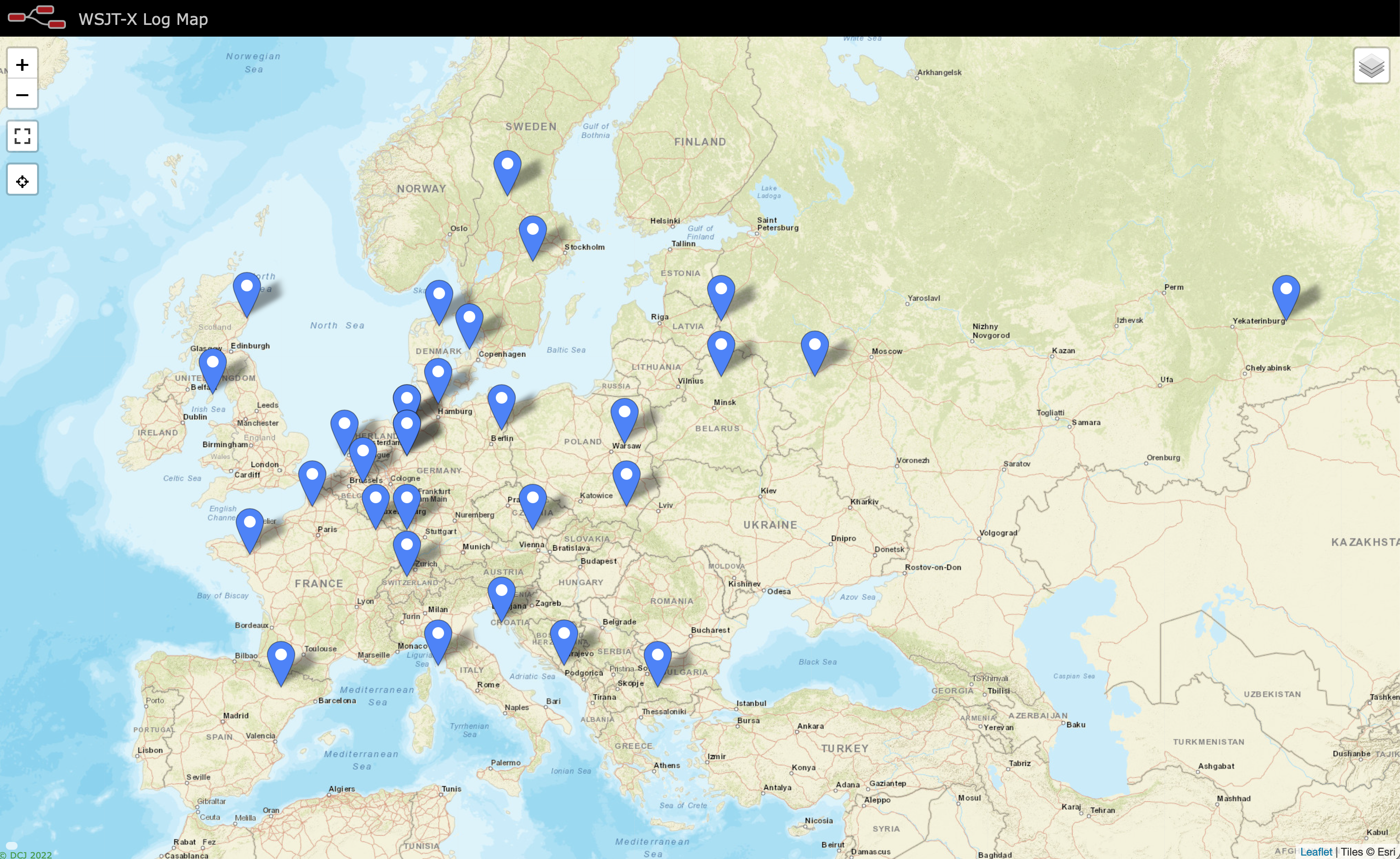
If you notice the above map there are 10 POTA sites (yellow dots) that I can easily access from my home in Kingston. All of them easily reachable via public transit or a bit of a walk. The one on the bottom right (the island) is not reachable via foot. There is a dock but I can’t find out if Kingston has a Water Taxi so if I can activate 10 out of 11 I will be pleased.

I guess I could also say that this would be a test of the station I will be using for Field Day this year. Not sure where I’m going to be yet but…. I know I’ll be participating from somewhere near Kingston.
.
Till next time
73bob
![]()