via Hackaday: College Gives You Practical Electronics
22 September 2024 at 05:45

Jeff, K6JCA, kindly sent me a paper, (Dunsmore 1991) which gives design details for a variation of the common resistive Return Loss Bridge design.
This article expands on the discussion at Return Loss Bridge – some important details, exploring Dunsmore’s design.
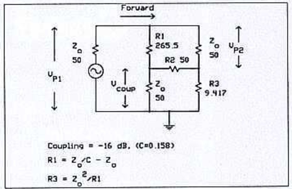
Above is Figure 3a from (Dunsmore 1991).
The Dunsmore’s circuit has been rearranged to be similar to that used in my earlier articles.

Above is the rearranged schematic for discussion. It is similar to that used in the earlier article, but three components are renamed, R1, R2 and R3.
To analyse the circuit, we can use the mesh currents method. Mesh currents i1, i2 and i3 are annotated on the schematic.
The mesh equations are easy to write:
\(V_s=(zs+r1+r3) \cdot i1-r1 \cdot i2-r3 \cdot i3\\0=-r1 \cdot i1+(r1+r2+zd) \cdot i2-zd \cdot i3\\0=-r3 \cdot i1-zd \cdot i2+(r3+zd+zu) \cdot i3\\\)This is a system of 3 linear simultaneous equations in three unknowns. In matrix notation:
\(\begin{vmatrix}i1\\i2\\i3 \end{vmatrix}=\begin{vmatrix}zs+r1+r3 & -r1 & -r3\\-r1 & r1+r2+zd & -zd\\-r3 & -zd & r3+zd+zu\end{vmatrix}^{-1} \times\begin{vmatrix}V_s\\0\\0\end{vmatrix}\\\)Lets solve it in Python (since we are going to solve for some different input values) for Vs=1V.
First pass: zs, zref, zd are 50Ω, and zu is short circuit (1e-300 to avoid division by zero) for calibration and 25Ω for measurement. This example uses Dunmore’s 16dB coupling factor to derive the values for r1 and r3.
from scipy.optimize import minimize
import numpy as np
import cmath
import math

zs=50
zref=50
zd=50
c=0.5
c=10**(-16/20)
r3=zref/c-zref
r1=50
r2=zref**2/r3

print(c,r1,r2,r3)

#equations of mesh currents
#vs=(zs+r1+r3)⋅i1−r1⋅i2−r3⋅i3
#0=−r1⋅i1+(r1+r2+zd)⋅i2−zd⋅i3
#0=−r3⋅i1−zd⋅i2+(r3+zd+zu)⋅i3

#s/c cal
zu=1e-300
#solve mesh equations
A=[[zs+r1+r3,-r1,-r3],[-r1,r1+r2+zd,-zd],[-r3,-zd,r3+zd+zu]]
b=[1,0,0]
#print(A)
#print(b)
res=np.linalg.inv(A).dot(b)
#print(res)
vcal=(res[1]-res[2])*zd
#print(vcal)

#check oc
zu=1e300
#solve mesh equations
A=[[zs+r1+r3,-r1,-r3],[-r1,r1+r2+zd,-zd],[-r3,-zd,r3+zd+zu]]
b=[1,0,0]
#print(A)
#print(b)
res=np.linalg.inv(A).dot(b)
#print(res)
vm=(res[1]-res[2])*zd
#print(vm)
rl=-20*math.log10(abs(vm)/abs(vcal))
print('ReturnLoss (dB) {:0.2f}'.format(rl))

#check 25
zu=25
#solve mesh equations
A=[[zs+r1+r3,-r1,-r3],[-r1,r1+r2+zd,-zd],[-r3,-zd,r3+zd+zu]]
b=[1,0,0]
#print(A)
#print(b)
res=np.linalg.inv(A).dot(b)
print(res)
vm=(res[1]-res[2])*zd
#print(vm)
rl=-20*math.log10(abs(vm)/abs(vcal))
print('Zu: {:.2f}, ReturnLoss: (dB) {:.2f}'.format(zu,rl))
This gives calculated rl=9.54dB which is correct. Also ReturnLoss for OC reconciles with the SC calibration.
This result is sensitive to the value of Zs and Zd, changing them alters the result. It may be that there are other combinations of Zs, Zd, r1, r2, r3 that give correct results in all cases.
A common manifestation of design failure is that ReturnLoss of a short circuit termination will be significantly different to an open circuit termination, and the difference may be frequency dependent when combined with imperfections in the bridge.
Jeff, K6JCA, published a very interesting article RF Directional Bridge: Operation versus Source and Detector Impedances that is relevant to the wider understanding of Return Loss Bridges.
Dunsmore gives an alternative design, though his formulas still depended on Zs=Zd=r1=Zref.
Dunsmore, J. Nov 1991. Simple SMT bridge circuit mimics ultra broadband coupler In RF Design, November 1991: 105-108.
I built a thing! This is a GPSDO using a PCB and kit of parts supplied by G8CUL and a OXCO from G1OGY. It uses a Jupiter GPS module which provides the PPS signal and a 10kHz output and the completed module provides 2x 10MHz and 1x 1MHz outputs. Although there are a number of such designs this one is nice in that it also has a display and shows the current date and time as UTC.
This was, I think my third SMD construction and certainly the Mose SMD devices including multi-legged chips. No issues in construction especially given the quality of the PCB that G8CUL had made.
The backup battery is a CR2 3.3V type and helps with warm starting. As the regulator gets hot I managed to fit a heatsink between it and the rear of the case and hopefully this will sort out heat transfer, otherwise I may need to bolt another heatsink on the rear. Construction in a die cast box would have been better maybe but the blue/white box fits in with others in the shack, plus I had it already! The bezel is cut down from a 3D printed one from Printables.com designed specifically for the 2×16 LCD displays. The button – which is not the best but I had one etc. – selects the various displays which include date and time, satellites seen, latitude, longitude, altitude and QRA locator.
I had a number of Molex pins to wire up recently. To make things easier I decided to use some 4-core signal cable I had but found that the insulation is so poor at resisting heat that soldering the Molex pins was a non-starter as it always ended up with bare wires. Of course, Molex pins are designed to be crimped… so off to eBay.
The latest addition to my toolbox arrived in a couple of days and made the job a lot easier.
Fox Flasher MkII and several follow on articles described an animal deterrent based on a Chinese 8051 architecture microcontroller, the STC15F104E.
Fox flasher MkII update 7/2019 documented a rebuild of the enclosure etc.
This is an update after five more years operation outside.

Above is a pic of the device. The polycarbonate case has yellowed a little. Importantly the cheap PVA has not crazed, it is kept dry by the outer enclosure, and a hydrophobic vent helps keeps the interior dry.
The battery is a pouch LiPo single cell, it is in good condition. A previous trial with 18650 LiIon cells showed they were unsuitable for the environmentals.
From Top to Bottom:
Not shown are my RigExpert VNAs, the NanoVNA, the Koolertron 60MHz function generator, the Tacklife 30V 5A variable DC power supply, and handheld digital multi- and LCR meters. On the bench is the Weller WE1010NA soldering station. Oh yeah, and my Elegoo 3D printer.
I think its turning into a proper little radio lab! State of the art, circa 1982!
KM1NDY
Some of you may remember that I used to collect valves. I started collecting when I was around 6 years old, although back then it was more to impress friends than collect. An old directly heated valve plus a Lego battery box lit my desk up at primary school. I did not start collecting in earnest until the 1990’s and launched my first online valve museum in 1999. Since then the collection grew in several directions at once, including German WW2 types, Russian Cold War types and British military and civilian types. There were specials from all over the world as well including a few Japanese WW2 ones. Valves ranged from tiny little things to a RD150YB that had to live in the garage, and a 6-anode mercury arc rectifier that was equally not allowed in the house, and for good reason too. The main collection grew to over 3,000 types, many of which had duplicates, so probably 4,000 in total. And then there were boxes of valves that did not warrant adding to the collection.
And so the collection continued to expand. While on holiday in the US friend in the US was discussing collecting trends with me and another collecting friend and said he collected US antique types, others collected microwave types and, pointing at me he said I collected everything and there is nothing wrong in that. But it made me think what exactly is my interest. And so I decided to concentrate on what I found most interesting – British military types, mainly in the CV, and A, N and V military series. The collection included a number of CRTs as well and eventually took over the whole garage.
I decided then to concentrate solely on CV types and trimmed the collection to 1,500 types, again with duplicates taking the collection to over 2,000 valves. Of the remainder many were sold and many hundreds went to the National Valve Museum which was nearly as old as my own.
Eventually though three things happened. First, it was becoming increasingly difficult to find new additions. Second, the website was now seeing fewer and fewer actual hits (as opposed to search engine spiders), and, most importantly I realised it had become an obsession. Time to quit. I also came to the realisation that I had an awful lot of valves in lots of boxes and I never even looked at any once they went into a box.
So I decided to close the website and sell off anything I could, donating the remainder to the National Valve Museum. The website was essentially converted to flat HTML files with none of the database behind them and taken over by a member of the BVWS. Of course, all praise to them for doing that, but none to me for all my years of work. Par for the course. In the past 20 years I received just a handful comments thanking me for providing the photographs and information about the collection. I was somewhat surprises at the screams when I announced the website was to close. Of course, I did not make the website for that, I did it because I thought people might actually be interested, and they clearly were back at the turn of the millennium but times change.
I was fortunate that someone local took many of the CRTs and a bunch of valves as well. Of the rest, a few hundred are destined for friends in Australia, the Netherlands, Belgium and Italy but the logistics are going to be a nightmare. Several hundred have found new homes here in the UK. Of the thousands left these went to the National Valve Museum with the more mundane radio and TV types being scrapped as no-one wanted to come and get them. I am keeping many of the early magnetrons for later sale, and some of the more decorative valves for, well, decoration!
There are still several boxes and a cupboard full of valves and they are destined to be scrapped. Selling on eBay as an individual has become more and more complex over the years so I will rarely sell there. As no-one was interested in paying me a visit to take them away they will end up in the dump.
At its height the collection took over half the workshop and half the garage. Once trimmed down to the CV types it was still half the workshop. Now it is all under one bench and I have more space to set up the various tools that have been sidelined for years and actually get back to working on the house.
Halibut Electronics is working on a new satellite antenna kit!
This is kinda cool for two reasons, first because we've recently started attending the high altitude balloon meetups at Noisebridge. Satellite antennas came up during one of the meetings.
More tactically importanly though, the EggNogs docs inspired what be a better tuna can feedtrough for Projct TouCan's antenna! For notes, here's my original EggNogs documentation review reply:
The documentation looks great so far! I've made it to page 17/22. One thing:
For those of us with partners heavily into fountain pens, those of us who like to print out manuals on JIS B5 paper and then store them in Kokuyo Campus binders, page numbers in the table of contents would be very cool. (I know, I know, such a niche group :) )
Mostly though, I wanted to thank you for jogging my memory into a, (I hope), better solution for Project TouCans antenna ports. At present, they're inverted bananna plug posts. Banana plug screw terminals are tiny, and therefore somewhat problematic in outdoor environments. Here's an idea of how tiny
![]()
![]()
Suspending a two pound rig 6 meters up, eventually the screw threads begin to strip. We stuck with banana plugs though because the insulator around the conductor makes them perfect for mounting in a tuna fish can. Yes, I've read about how Yagis and dipoles are balanced and therefore have 0 volts across the antenna center, so theoretically you don't need insulators, but TouCans frequently hangs at angles to the ground and/or very close to the ground, so, insulators.
![]()
Anyhow! The last figure on page 17, the one with the cool weather-proof washer, reminded me that gromets exist! With the correct sized gromet, we can put any size bolt pointing upward as an antenna connector.
![]()
And, even better still, we can source them from our local hardware store at the bottom of the hill!
Thanks Mark!
72 de KD0FNR Hamilton
It was not all that long ago that I tried unsuccessfully once again to make an AM radio receiver from discreet components and an LM386 low voltage power amplifier.
Well, apparently the fifth time is a charm…because THIS ONE WORKS!!!
As you can see in the video and pics below, there are only really a handful of components. Two ICs, the LM386 and a LM741 op-amp. That is a 10-365pF capacitor on the left in parallel with a homemade coil. A 10K potentiometer in the middle. An 8-ohm 0.5W loudspeaker. An 1N34A germanium diode. Some electrolytic caps and some resistors. A alligator-clamped a few feet of wire to one end of the inductor as an antenna. The LM741 requires both a positive voltage and a negative voltage, in this case +9V and -9V to function.
I think in making this particular receiver work, it was in part the careful construction of the tuning coil. I have a much better understanding now of LC circuits that I previously did. I knew how to utilize a inductor and LC frequency formulas (and online calculators!) to achieve a coil that along with a variable capacitor could be tapped to achieve resonant frequencies within the AM broadcast band (540kHz to 1700kHz). I used 26 gauge magnet wire wrapped 70 times around a 1 5/16″ PVC pipe. The enamel was scratched off in between the two pieces of electrical tape, trying to expose the outer surface without causing shorts between adjacent coils. A wiper was constructed from a bent piece of 14awg solid wire, and grounded. One end of the coil was also grounded (using the same screw as the 14awg wiper, which was then grounded on the breadboard with the rest of the circuit). The other end of the coil attached to the antenna, and also back into the circuit on the breadboard. The antenna and coil are directly connected to the germanium diode.
The variable capacitor (left) is in parallel with the tuning coil. The leftmost IC is the LM741 which requires the dual positive and negative voltage sources. After crossing the germanium diode, the now rectified signal passes through the LM741 op-amp. This feeds through a 10K potentiometer that can increase the volume of the signal as it enters the LM386 which further amplifies the audio before passing it into the loudspeaker.
Unfortunately, this circuit is copyrighted. It is from one of Forrest M. Mims III’s “Engineer’s Mini Notebook” of prior Radio Shack fame. In particular it is part of Volume II of the four volume set, called “Science and Communication Circuits & Projects”. Volume I, “Timer, Op Amp & Optoelectronic Circuits and Projects” is also handy in getting the dual power supplies correct. I ordered the entire compendium from Solarbotics. As always, I receive absolutely no payment or products for this website whatsoever; this is an entirely non-monetized personal endeavor so don’t think I care if you visit that site or not. These books just seem very hard to find these days, and I was just lucky to stumble upon this company that had them for sale. I may not be the only one that feels that way.
Finally! A working DIY receiver! There is still a lot of experimentation to do with this one. Like will a Schottky diode work instead of germanium unobtanium? I will let you know what I find out!
You are always on my mind.
KM1NDY
This was a little rabbit hole. On some amateur radio forum somewhere someone mentioned the MFJ-802B RF Field Strength Meter. This piqued my interest because I had not realized that a field strength meter was a consumer accessible device. Turns out there are all sorts of RF meters and detectors available to purchase. Who knew?
This collided me into the homebrew versions of RF detectors. One that caught my eye, and inspired this project was “The Squeakie” by VK3YE. It requires a handful of components, all of which I had. I built it mostly to spec on a breadboard, adding only an extra trimpot to control the volume. Then I soldered it onto perfboard and it, after a bit of troubleshooting, worked exactly as advertised. In short, it squeaks at a proportionally higher pitch when it encounters radio waves. This means it is useful as an audible RF field strength meter. You could use it to detect RF while fox-hunting, or to test the radiation pattern of an antenna, or to annoy your significant others… In short, it is a voltage-controlled oscillator that increases in frequency in the presence of an RF signal.
So I built The Squeakie, and sure enough one tap on my HT, and the little guy was shrieking. Below gives you a rough sketch of how I positioned and connected everything. This perfboard is of the type that all of the holes in each individual row are interconnected (and represented by the printed lines on the page).
So how exactly does The Squeakie work? My modification of VK3YE’s Field Strength meter is shown in part below (circuit constructed with Multisim).
Let’s start with D1, which is the switching diode 1N4148. In this application, the diode is acting as a rectifier, transforming an RF signal coming from the antenna into direct current.
Next let’s discuss the 555 Timer IC. This circuit is set up in “astable” mode, which means that the 555 timer is going to oscillate between an output of VCC and zero volts indefinitely with a regular and predictable voltage-dependent frequency. The tying of the threshold (pin 6) and trigger (pin 2) together puts the 555 in a permanently unstable state flipping between “on” (with a voltage equivalent to that seen on pin 8, i.e. VCC) and “off” (zero voltage) producing an endless square wave.
Resistors R1 and R2, along with capacitor C3 work together to produce the frequency of the 555 Timer output. In the situation where VCC is the only voltage source, the threshold/trigger flip-flop produces a stable oscillation. But in our circuit, the antenna acts as an additional voltage source in the presence of RF, adding to the VCC, and resulting in more swift oscillations (i.e., an increase in frequency of the output square wave signal).
The VCC crosses the R5 resistor, 20kΩ potentiometer, and the R4 resistor , which act as an adjustable voltage divider, creating a forward bias on the 1N4148 diode. The 20k POT can be adjusted to increase or decrease the voltage either toward the diode or toward ground, and in turn, change the frequency of the timer output. An additional voltage supplied by the antenna and rectified by the diode will increase that frequency.
The output voltage, rhythmically oscillating between VCC and zero volts, will cross through an electrolytic capacitor and to an 8Ω 0.5W loudspeaker whose volume is controlled by a 200Ω potentiometer. Running in parallel to the loudspeaker is also an LED that’s brightness will be increased or decreased with the frequency (and duty cycle) of the timer. And also an output lead to provide a readable input to a microcontroller is also available. In this case I used an Arduino Nano as well as a 1602 LCD screen.
The above EasyEDA schematic shows my entire finalized project. Or I supposed at least version 1.0. This includes placement of a DPDT switch (SW1) to switch from the Nano to the loudspeaker. A second switch (SW2) to switch the output to the Nano on or off. Three 2-port terminal blocks for the voltage source, antenna, and loudspeaker. The Arduino Nano and it’s connections to the 1602 LCD screen. And finally, the code I programmed for the Nano that would convert the output reading of the RF meter into a corresponding number. I’ll talk more about the code later on.
Below shows the entire breadboarded project, fully operational. In my version, not only does it squeak in higher frequencies (and have an adjustable volume) in the presence of RF above ambient background noise, it also brightens an LED proportional to RF signal strength, and displays a relative numerical meter reading. The antenna is just a length of wire tied into the positive port of the terminal block.
And just a close-up of the placement of the components. You will notice that the readout number is much less bright than the words “RF Strength”. I think this is due to the very quick oscillations of the device, of which I tried to account for somewhat in my rudimentary code. Hey, what can I say? It needs work.
I did go ahead and convert my EasyEDA schematic into a PCB through JLCPCB. Remember, I do not accept sponsorship from anyone. I actually cannot believe how easy it is to acquire a circuit board from this company.
The unpopulated rendering of the PCB is shown below. And the partially populated board is above.
And an exact Bill of Materials below.
And finally the code!
#include <LiquidCrystal.h>

int rs=7;
int en=8;
int d4=9;
int d5=10;
int d6=11;
int d7=12;
LiquidCrystal lcd(rs,en,d4,d5,d6,d7);

int maxVal = 0;
uint32_t lastSample = 0;

void setup() {
  Serial.begin(9600);
  lcd.begin(16,2);

}

void loop() {

    if (millis() - lastSample > 1000) {
        lastSample = millis();
        Serial.println(maxVal);
        maxVal = 0;

    }
    int reading = analogRead(1);
    if (reading > maxVal) {
        maxVal = reading;
    }
        lcd.setCursor(0,0);
        lcd.print("RF Strength: ");
        lcd.print(maxVal);
        lcd.clear();


}


What can I say? The firmware sure isn't pretty, and it doesn't even give you great results. But it does kinda work. I will probably spend some time working out different ways to produce more meaningful results from the readable Nano lead of this device.
This was a great and instructive project to work through for me. It also lends itself to a really easy soldering project for hams, or students, or individuals, particularly if you only build the part with the loudspeaker, or even the original “The Squeakie”. I think it is putting me one step closer to building my own receiver, which is something I have made a few attempts at so far.
May we meet again!
KM1NDY
OpenEMS, an open-source tool for simulating electromagnetic structures, has been a valuable resource for the scientific community for some time. Its capabilities continue to expand, thanks to ongoing contributions that add new functionalities. While...
The post A short tutorial to simulate your Kicad PCBs in openEMS using Gerber2EMS appeared first on Nuclearrambo.
For last year’s Field Day, I took a stab at networking a couple of computers together with an ethernet cable so that our N1MM+ logging software could be synced up. It was both surprisingly easy to do, but equally daunting due to the curious lack of reasonably digestible tutorials tackling the topic on the interwebs. So now that Field Day is again upon us, I felt that same sort of dread that comes from staring up at a steep learning curve. Because quite frankly, I could not remember at all how to create a N1MM+ computer network. I checked back at my blog page on the topic, and was dismayed at how little of the process I documented. So, I am here to rectify that.
Here is my use case. I want to have three computers with Windows 10 operating systems host logging software (N1MM Logger Plus) for a multiple station ARRL Field Day event. All of the computers need to be synchronized with each other in order to avoid such dreaded contesting faux pas as “dupes”, i.e., getting the same person twice. I also do not want to have to rely on an internet in order to maintain communication between these computers.
As far as hardware goes, I already was in possession of three (quite aged) computers. I splurged on three new 25′ ethernet (CAT 6) cables (one for each computer), and a Linksys 8-Port Gigabit Ethernet Switch. I set up the computers simply by plugging one end of an ethernet cable into its ethernet port, and the other end of the cable into the switch. Remember the gigabit switch does need power to operate!
Before I began networking the computers, I had updated all of the necessary software, including Windows and N1MM+. All of the computers need to have the exact same version of N1MM+, as well as exactly the same inputted contest information, before N1MM+ is able to synchronize between multiple stations.
Once the hardware was gathered and the software was up-to-date, I followed the step-by-step procedure documented below.
Step 1: Go to internet icon, click, and “Open Network & Internet Settings”.
Step 2: Select “Ethernet” on left, and then “Network and Sharing Center” on right.
Step 3: The “Unidentified Network” is set to “private” which is what I want it to be. For contrast, my wifi network is set to “Public” (see arrow on the left). Click on the “Ethernet” hyperlink.
Step 4: Click on “Properties” of the first box that pops up. Then click on “Internet Protocol Version 4 (TCP/IPv4)”.
Step 5: Click “Use the following IP address” and add in “192.168.1.200” for “IP address”. The “Subnet mask” should just show up as 255.255.255.0. While I am no expert by any means in networking computers, I do think you can choose the last three digits of your IP address from 1 to 255 254 [Correction sent to me by my favorite critic, AC1JR!] I picked “200” rather arbitrarily. Once you are done, click “ok”, “ok”, and “close” on the multiple windows.
Step 6: If you need to make your network private because it is showing as public (see Step 3 above), you need type “secpol.msc” into the search bar and press enter.
Step 7: In the pop-up window, click on the “Network List Manager Policies” under the “Security Settings” tab. Then click “Unidentified Networks”. In the next pop-up, choose “Private”. Hit “Apply” and then “Ok”. Your “Unidentified Network” settings should now say “Private”.
Step 8: Open the file manager and click on “Network”. Your computer’s name should be listed there. My computer is named “PC-1”.
Step 9: Now it is time to network your second computer. Go back through Steps 1-8, but this time on the new computer. Below shows all of the steps ordered numerically. Don’t forget to change the ethernet connection to “Private” as shown above. The only difference is that you want to assign this computer a different IP address than the first one. I chose 192.168.1.201.
Step 10: Check the “Network” tab in the file manager to make sure the second computer (in my case, “PC-2”) shows up.
Step 11: Repeat these steps as many times as you need to in order to connect all of your computers to the network. Just change the last digits of the newly assigned static IP address, as they all have to be something different. I have three computers that are now linked together.
Step 12: Once your computers are all networked, open N1MM. Under the “Window” menu, find and click “Network Status”.
Step 13: Make sure that the most recent version of N1MM is installed or else you will get an error message when attempting to connect to the other networked computers (in red below). You also need to make sure that everything else about N1MM is identical, in particular that the contest information for the log is the same.
Step 14: When all of the computers are identically set-up, with the same software versions and contest information, open up the “Network Status” window. A bubble will show that gives you an option to turn on “Networked Computer Mode”. Click it!
Step 15: If you see all of your computers listed with no red error messages, your networking efforts are a success! Make sure you have designated one of the computers as the “Master” by checking the appropriate box.
There you have it! N1MM Logger Plus synchronized across multiple stations for Field Day! I hope to catch you on the air!
Forever,
KM1NDY
With ARRL Field Day around the corner, it is the time of year where amateur radio operators far and wide wonder if they are going to be stuck having their QSOs wiped out every time their neighbor keys up the microphone. Interference between stations in a multi-transmitter field day operation can be the norm if you didn’t think to use band pass filters.
So out my stash of little gray metal boxes came, and I began checking their VSWRs for a down-‘n’-dirty pre-Field Day check-a-roo…
I don’t love the VSWR trace of this 6M filter, but it will probably suffice for Field Day, where I plan on setting up a 6M 4-element beam, and operating largely on FT8 to try to intercept the “Alpha” stations that are trying to rack up the “Free VHF station” points. That, and when else do I get to put up my 6M yagi???? FT8 is operated on 50.313 MHz which should have a VSWR under 1.2.
These Array Solutions elliptic filters have a beautiful looking VSWR. I really wish I had spent my ham bucks acquiring a full set of these. Apparently Array Solutions is not making them anymore, but a company called Hamation is? Oh, and for anyone not familiar with the RigExpert Antenna Analyzer (1-port VNA), the blue portion of the display indicates the ham band with frequency along the horizontal access and VSWR on the vertical access. Keep in mind that the VSWR we want is as close to 1 as possible!
Now 12M is a WARC band of course, meaning you cannot use it for contesting. In general, it is second only to 60M as my least used band. But, boy, that band pass filter looks great!
I expect 15M to be hopping on Field Day. I am glad this filter looks good.
Another WARC band, i.e. Field Day no-go… But a good looking filter!
Now 20M. Let’s just say I am not at all happy with this filter. Granted, it has probably been heavily abused over its several years now with me. Dunestar has gone out of business since August of 2023. Their original owner became a silent key right around the time that I purchased this set. I decided to try out Morgan Systems Surestop bandpass filters for 20M and 40M for this year’s Field Day. You’ll notice the 40M filter looks reasonable, but when actually under use, the VSWR seen at the transceiver is often high. And we can’t be without a highly functional 20M and 40M stations when it comes to Field Day operations. We will see how the Surestop filters behave…
The 30M filter looks superb! Of course, there is no operating 30M on Field Day.
The 40M filter looks a bit janky. Technically, it should function okay. But like I mentioned, this filter often creates a high SWR at the transceiver. I have a replacement here for it now.
Ugghh. The 80M filter is downright scary looking. I probably should have replaced it when I had a chance.
The top band filter isn’t great. What else can I say? I am not sure I ever even used this filter on 160M. I do think I will slowly start replacing my filters with one of the other manufacturers with time. Although I am grateful to have been able to get a set of Dunestar filters, especially since they provided a boatload of good multi-operator experiences over the years, the older and wiser me wishes I had put my money elsewhere.
Here are the “guts” of one of the Array Solutions 3rd order elliptic filters. Note the interesting use of a hot glue like substance to hold the windings in place, the beefy size of the enameled wire, and the use of ceramic capacitors. Silver-Mica capacitors are often recommended for use in band pass filters
…and a representative schematic from this excellent LC Filter Design calculator by Marki Microwave…
Now we can contrast the design and construction of the Array Solutions band pass filter with the 2nd order Dunestar bandpass filter (below). This design consists of two airwound coils and capacitors mirroring and shielded from each other on the input and output side.
Every time I get around to thinking about, testing, and opening up my band pass filters, I can’t help but think: It would be so much better to make these myself. For some reason, this does not seem to be an area that has been overly tackled by hams. In fact, there is really only one prevailing design by Lew Gordon K4VX, a 3rd order Butterworth filter, that is well-described and seems easy-ish to reproduce by the average everyday ham (i.e., one that does not design RF products for a living). The W3NQN band pass filter design article is a much more complex document to follow.
I have dabbled in making band pass filters before, but have found myself hindered by the testing process. I since learned to use the “low Z” setting of my oscilloscope. So, once I again, I found myself constructing an ugly little device, this time a low-power 160M version of K4VX’s Butterworth filter. The schematic, construction, and component values are all documented in the article. This is nothing more than a capacitor (~4000 pF) and inductor (~2.2 µH) connected in parallel on the left hand side as well as a capacitor (~4000 pF) and inductor (~2.2 µH) connected in parallel on the right hand side, with another capacitor (~400 pF) and inductor (22 µH) in series in the middle connecting the two sides. I just soldered everything together and attached it across VHF connectors.
And although the Marki Microwave design tool proposes different capacitor and inductor values for its version of the 160M 3rd order Butterworth band pass filter, you can still get an idea of what the schematic, and scatter plot parameters (insertion loss and return loss) of the filter should look like.
The first test I performed with the band pass filter was pass a sine wave through it from below the 160M band (which spans from 1.8 MHz to 2 MHz). I started with 500 kHz and passed the signal into my oscilloscope, making sure to turn on the low impedance (50 ohm) setting.
I did indeed have a fairly weak signal.
When I increased the signal generator frequency so that the waveform outputted was within the pass band of the filter (1.8 MHz), the oscilloscope showed a much larger voltage. Keep in mind that it is Channel 2 (“CH2”, the bottom box!), that you want to be looking at on the signal generator if you are following along with the pictures.
There is no change to the oscilloscope settings between the 1.8 MHz input (below) and the 500 kHz input (earlier). Clearly the voltage recovered at the 1.8 MHz setting is much larger.
Now to take a look at the NanoVNA results. The filter was simply placed between port 0 and port 1 of the NanoVNA. The vertical gray bar represents the frequency range of the 160M ham band. The filter I constructed did not use components of the exact values recommended in the K4VX article, thus the reason the filter performs at a lower frequency than expected.
Regardless, you can see below that the shape of the S11 (return loss) and S21 (insertion loss) parameters are very similar to that predicted by the Marki calculator. My filter is below:
And, again, the S11 and S21 parameters as predicted by the Marki calculator:
Well, there you have it. Band pass filter season! Field Day is almost here, and we are going to go with what we have. However, my mind has been spinning around the idea of constructing my own band pass filters so that I can more easily fix and replace the rather fragile devices as needed. And although this was a tiny little experiment, I think it shows that these band pass filter designs are indeed reproducible with accuracy. Will a KM1NDY band pass filter design show up here in the near future?! The Magic 8 Ball says “Reply Hazy. Try Again Later”!
Catchya on the flippity flip!
KM1NDY
So much for playing radio this weekend. In the last half hour my 200mW Zachtek WSPR transmitter, cycling from 80M to 10M every 15 minutes or so, managed to be heard in 2 places… Both in Boston and presumably by ground wave.
By comparison, here is a half hour block from a good propagation day:
Simply amazing! Enjoy the Aurora!
KM1NDY