OpenEMS, an open-source tool for simulating electromagnetic structures, has been a valuable resource for the scientific community for some time. Its capabilities continue to expand, thanks to ongoing contributions that add new functionalities. While...
We’ve recently added a new room to the Matrix HAM Radio Space for Digital Voice modes as this was an area of interest that didn’t really fit into any of the other rooms.
The new Digital Voice room has attracted a lot of attention from members, with a lot of the focus being on the AllStarLink system. Michael, DK1MI built an AllStarLink node in the cloud for us all to use for Matrix Nets and so I decided I had to get in on the fun.
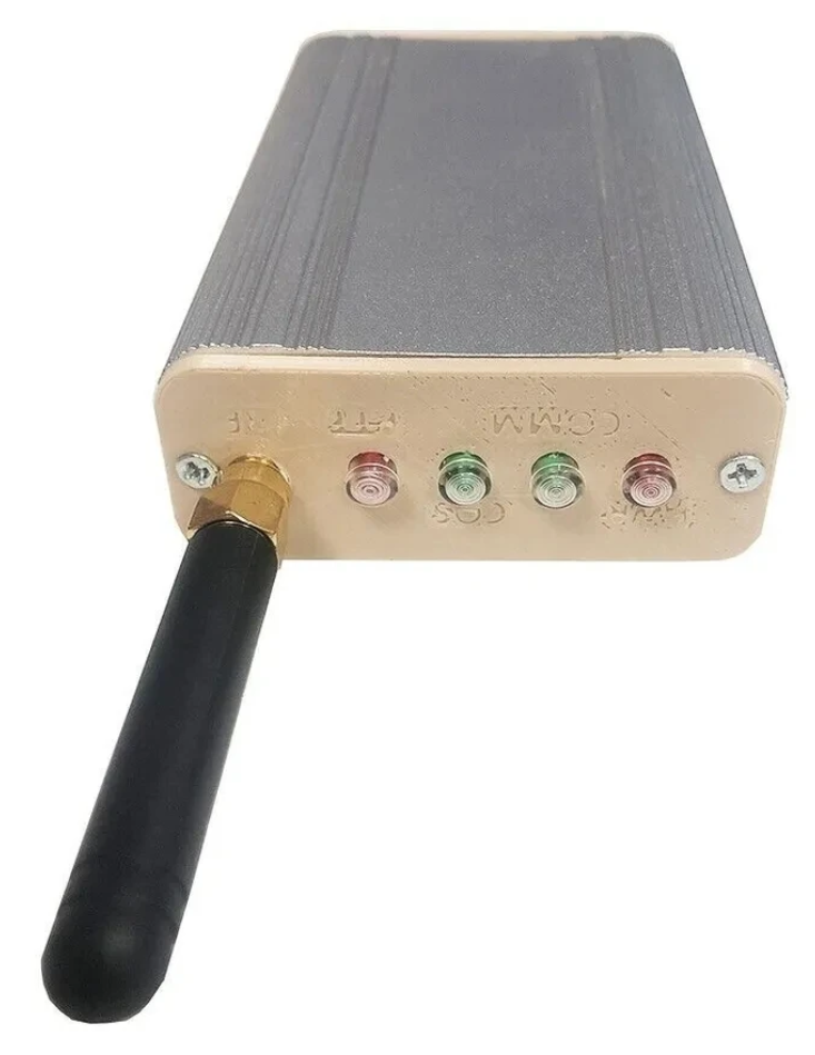
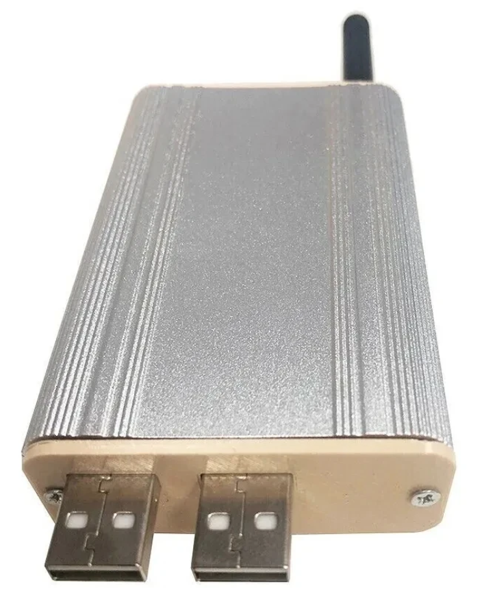
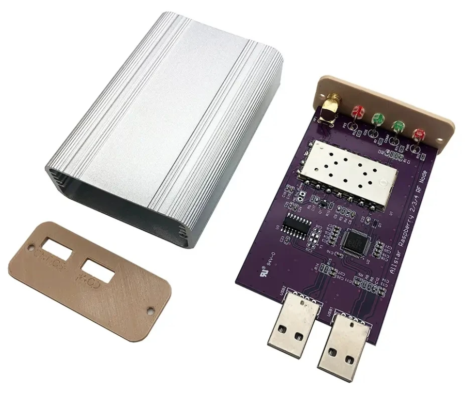
Jumbospot SHARI SA818 Amateur Radio AllStarLink Radio Interface Front Panel ViewJumbospot SHARI SA818 Amateur Radio AllStarLink Radio Interface Rear ViewJumbospot SHARI SA818 Amateur Radio AllStarLink Radio Interface stripped down View
The two USB connectors on the SHARI device are position such that they plug into two of the available 4 USB ports on the RaspberryPi without the need for cables. This keeps the whole solution together in one neat package.
Before you start you will need to obtain a node number and secret (password) from the AllStarLink Portal. To get this you will need to provide proof to the AllStarLink administrators that you are a licensed Amateur Radio (HAM) operator. This is done by uploading a copy of the first page of your HAM licence to the website for the admin team to check. This can take 24hrs to be completed so make sure you get this all done before trying to build your node. You cannot build a node successfully without a node number and secret.
Of course you will also need a transceiver that can operate on the 438.800Mhz frequency or other frequency of your choice on the 2m or 70cm HAM band.
You will also need to open port 4569 on your internet router and setup port forwarding to the IP Address that you will be using on your RaspberryPi node. It’s important to use a static IP Address on your RaspberryPi.
There are quite a few different Linux based operating system (O/S) images that are available for the RaspberryPi devices that have been specifically tailored for the AllStarLink node and include all the necessary software and library packages out the box.
Once downloaded you need to burn the ISO image onto a suitable SD card for your RaspberryPi. I use BalenaEtcher as it’s extremely quick and reliable at burning ISO images to SD cards.
Of course if you are a hardline Linux command line junkie you can always use dd to create the SD card.
Once you’ve got your O/S onto your SD card, slot it into your RaspberryPi making sure your SHARI device is connected to the two USB ports and then power it up. Make sure you have a good PSU for the RaspberryPi as the two devices together draw around 3A of current during the transmit cycle. (I use a 3.6A PSU from Amazon).
The default login for the Raspbian O/S is shown below. Login via SSH and configure your RaspberryPi for your local network. It’s important to use a static IP Address configured either directly on the RaspberryPi or via DHCP in your router.
Next you need to change directory into the asterisk config file directory using the command shown below:
cd /etc/asterisk
In this directory you will find all the default config files that come as part of the distro. For this build we’re not going to use them and so we need to move them out of the way ready for a set of config files that have already been configured correctly.
Using the following commands create a new directory, move into that new directory and then move all the unwanted configuration files into it:
mkdir ORIGINAL-CONF-FILES
cd ./ORIGINAL-CONF-FILES
mv ../*.conf ./
ls -la
cd ../
You should now be back in the /etc/asterisk directory which will now be empty apart from the custom directory which we left in place.
You now need to copy the correctly configured configuration files into the /etc/asterisk directory. Start by downloading the zip file containing the new configuration files
Once downloaded, copy the .zip file into the repeater users home directory (/home/repeater) using either scp on the Linux command line or if using Windows you can use the FileZilla Client in SFTP mode using the login details above.
Once you have the .zip file in the repeater user’s home directory you need to copy the file into the /etc/asterisk directory as user root:
The gpioBASH script and configuration details were supplied by Mark, G1INU in the Digital Voice room on the Matrix. It adds the COS light functionality to the setup. The COS light will now light every time the SA818 hears RF on the input.
The next thing you need to do is configure the SA818 radio device in the SHARI. The script I used was originally from https://wiki.fm-funknetz.de/doku.php?id=fm-funknetz:technik:shari-sa818 all I’ve done is change the entries to switch off CTCSS and changed the frequency to 438.800Mhz. Configuring the SA818 is done by running the SA818-running.pyPython programme that you moved into the repeater user home directory. Making sure you are still user root, run the following commands:
cd /home/repeater
./SA818-running.py
At this point your SHARI SA818 device will be configured to operate on 438.800Mhz and CTCSS will be disabled.
If you want to change the frequency or enable and set a CTCSS tone to access the node you will need to edit the Python programme using your favourite text editor and change the entries accordingly. Once changed rerun the program as shown above and your SHARI will be reconfigured to your new settings.
Next you need to move the allmon.ini.php file into the correct directory so that it enables access to the Allstar Monitor web page on the device so that you can manage connecting/disconnecting nodes. Use the following commands as user root to achieve this:
The allmon.ini.php file needs to have your node name entered into it for it to work correctly. As user root, change directory and edit the file using your favourite editor.
cd /var/www/html
Using your text editor, search for the line starting [XXXXX] and change the XXXXX to your node number. Save the change and exit the file.
At this point you are almost complete, all that is left to do is add your node number and node secret into the appropriate configuration files in the /etc/asterisk directory.
Since I am a Linux command line junkie I use vi to edit all the configuration files on the command line as user root, but you can use any editor of your choice.
cd /etc/asterisk
Start with the extensions.conf file. Search for the line starting with NODE = and delete the XXXXX entry and insert your node number. Save the file and edit it.
Next you need to edit the iax.conf file. This time search for the line starting with register= and change the XXXXX for your node number and the YYYYYYYYYYYY for your node secret. Be careful not to accidentally delete any other characters in the lines otherwise it will corrupt the configuration file.
In the same file search for the two lines that start with secret = and change the YYYYYYYYYYYY for your node secret. Once you have changed both of the secret entries, save and exit the file.
The final file to edit is the rpt.conf file. Once again open the file using your favourite editor and search for the line starting with XXXXX = radio@127.0.0.1:4569/XXXXX, change the XXXXX entries for your node number making sure not to delete any other characters next to the XXXXX entries.
Further down in the same file there is a line that starts with [XXXXX], once again change the XXXXX for your node number making sure to keep the square brackets at each end of the node number as you edit it.
Finally move down to the very bottom of the file and find the two lines that start with /home/repeater/gpio, once again change the XXXXX entries for your node number.
Once this is done, save and exit the file. At this point your node should be fully configured and will only require a reboot to get it working.
As user root, reboot your raspi using the reboot command.
reboot
Once your raspi comes back online, login using SSH as user repeater and then become root user using the sudo command detailed above.
You now need to create the admin user password for the Allstar Monitor web page on the device. This is done using the following commands as user root:
cd /var/www/html/
htpasswd -c .htpasswd admin
You will be asked to enter a password twice for the admin user, make sure you make a note of this password as you will need it to login to the web page.
Once this is done your configuration is complete, logout from the terminal session by entering exit twice (once to logout as user root and another to logout as user repeater).
Using your favourite web browser enter the IP Address of your raspi into the URL bar as shown below:
http://<Your-Raspi-IP>/allmon2
Note: remove the <> from the URL once you have entered the required information.
Once this is done you should be presented with your node control panel as shown below.
First visit to the AllStar Monitor Web Page
Login using Admin and the password you set above and you are now ready to start using your node.
It’s a good idea to connect to node 55553 which is a parrot test node to check your audio levels. you can do this by entering the node into the field at the top left and pressing the connect button.
M0AWS AllStarLink Node 61928 connected to 55553 Parrot
Once connected, tune your radio to 438.800Mhz FM and transmit a test message using your callsign and test123, or something similar. The parrot will then play your recording back to you so that you can hear how you sound. It will also comment on your audio level as to whether it is OK or not.
You are now connected to AllStarLink network and have the world at your finger tips. Below is a small list of nodes in the UK, Australia and America to get you started chatting with other HAMs via your node.
55553	ASL Parrot for testing
41522	M0HOY HUBNet Manchester, UK
60349	VK6CIA 439.275 Perth, Western Australia
51077	VK6SEG South West Hub B Albany WA
2167	M0JKT FreeSTAR UK HUB 2 freestar.network
53573	NWAG NW AllStar Group Lancashire, UK
27339	East Coast Hub Wilmington NC USA
M0AWS AllStarLink Node 61928 sitting on the equipment rack
Thanks to Michael, DK1MI for building and hosting the Matrix HAM Radio Space AllStarLink Node (57881) and getting us all kicked off into the world of AllStarLink!
We hope to be having regular Matrix Net’s on the node soon for all Matrix members and visitors. We’ll organise days/times via the Digital Voice room.
Over on YouTube sn0ren has uploaded a well produced video to help beginners to the radio hobby understand antennas. The video explains how antennas work in theory, and how to choose the best antenna for your SDR and application through calculations and use of a Nano VNA.
There is an essential gadget that you will want to get, to get the best antenna performance. But first we need to cover a bit of antenna theory, before we can answer the question of what antenna that is the best one for your HackRF Portapack, or Flipper Zero SubGHZ module, or Meshtastic, Quansheng UV-K5, RTLSDR or other radio devices. This video is covering the bare minimum basics of antenna theory for beginners into the radio hobby.
Wir haben den SharkRF openSPOT 4 Pro für euch getestet. Unsere Erfahrungsbericht. Wenn es keine Infrastruktur wie Relais in deinem Einzugsbereich gibt, du aber dennoch am Funkbetrieb teilhaben möchtest, bietet sich ein Hotspot an. Dieses, meist kleine, Gerät ermöglicht es dir, deine Funkgeräte und Zubehör zu verwenden, so das richtiges Funk-Feeling aufkommt. Der Unterschied liegt … SharkRF openSPOT 4 Pro: Hotspot für die Hosentasche weiterlesen
The AD9913 direct digital synthesizer works as a digital waveform synthesizer that can generate signals with very precise resolution. When it comes to radio receivers, the AD9913 with <0.05Hz resolution can be used as...
Back in early February we reported about how the Canadian government is making plans to completely ban the Flipper Zero, and popular pentesting tool. The wording from Dominic LeBlanc, Canada's Minister of Public Safety, also implies that software defined radio devices could also be banned.
The reason for the ban is because the Canadian government claims that Flipper Zero and 'consumer hacking devices' are commonly being used as tools for high tech vehicle theft. However, as mentioned in the previous post, this has been debunked.
The team behind Flipper Zero have recently started a petition on change.org to stop the ban. At the time of this post the petition has already reached over 8,000 signature. The team have also penned a comprehensive "Response to the Canadian government" blog post, explaining why the ban makes no sense. In the post they debunk the myth of Flipper Zero being used for car theft, and show the real way high tech car theft is being done.
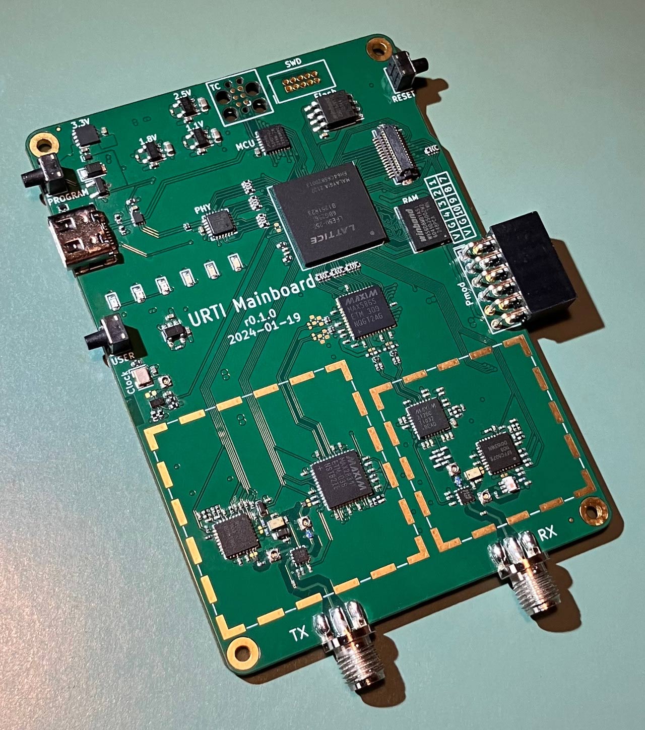
Over on their GitHub, Great Scott Gadgets, creators of the popular HackRF SDR, have created a phase two progress report for their upcoming URTI product. URTI (Universal Radio Test Instrument) is their next generation software defined radio which will work not only as a full-duplex SDR transceiver, but also as a vector network analyzer, spectrum analyzer and more.
In the phase two update they note that they have completed fabrication of an initial prototype board and have confirmed that all components on the board are functional. They note that much of phase four was already completed in parallel, which means the firmware and gateware development is also close to completion. So hopefully we will see more updates soon.
It was only through Sadguru Shree Aniruddha Bapu’s arrangement for us to be present as a support function for the “Old is Gold” distribution in remote villages that I had the chance to operate...
Cure for stray RF on my signal. And here's the $10 permanent fix: Also works on decoupling magnetic field hum from a pole pig transformer in a linear amplifier.
The PlutoSDR Rev C brings out both the transmit and receive channels. Thus, making it an even more capable device, especially for advanced RF stuff. A phased array is an advanced RF application that...
Hey there, fellow electronics enthusiasts! If you’ve ever tinkered with the signal generation, you’ve likely come across the AD9833 waveform generator chip. But did you know that this little gem can do so much...
In an article I wrote long time ago, I measured the noise figure of an amplifier using only a spectrum analyzer. The method I used was relatively simple but it took some mathematical understanding...
Our designs are becoming faster to serve our ever-growing demands from machines. Speed brings more complexity to the design. The usual slow transitions from 0 to 1 and 1 to 0 become so fast...
A 23cm hairpin filter operates around the 1.296GHz amateur radio band. The frequency being low enough allows us to fabricate it on a low cost FR4 substrate. It operates as a bandpass filter. There...
The Analog devices PlutoSDR comes with the AD9361 chip. Meant for learning, the PlutoSDR comes at a much more affordable cost as compared to the USRP. Of course, the USRP has its own advantages...
Update: this project is evolving. See this page for the latest version. Kits are available in the shop area. The announcement of the MRF300 and MRF101 transistors by NXP in 2018 has generated quite a spark of interest in the amateur radio community and as soon as I learned about them I wanted to get some […]