OpenEMS, an open-source tool for simulating electromagnetic structures, has been a valuable resource for the scientific community for some time. Its capabilities continue to expand, thanks to ongoing contributions that add new functionalities. While...
For last year’s Field Day, I took a stab at networking a couple of computers together with an ethernet cable so that our N1MM+ logging software could be synced up. It was both surprisingly easy to do, but equally daunting due to the curious lack of reasonably digestible tutorials tackling the topic on the interwebs. So now that Field Day is again upon us, I felt that same sort of dread that comes from staring up at a steep learning curve. Because quite frankly, I could not remember at all how to create a N1MM+ computer network. I checked back at my blog page on the topic, and was dismayed at how little of the process I documented. So, I am here to rectify that.
Here is my use case. I want to have three computers with Windows 10 operating systems host logging software (N1MM Logger Plus) for a multiple station ARRL Field Day event. All of the computers need to be synchronized with each other in order to avoid such dreaded contesting faux pas as “dupes”, i.e., getting the same person twice. I also do not want to have to rely on an internet in order to maintain communication between these computers.
As far as hardware goes, I already was in possession of three (quite aged) computers. I splurged on three new 25′ ethernet (CAT 6) cables (one for each computer), and a Linksys 8-Port Gigabit Ethernet Switch. I set up the computers simply by plugging one end of an ethernet cable into its ethernet port, and the other end of the cable into the switch. Remember the gigabit switch does need power to operate!
Before I began networking the computers, I had updated all of the necessary software, including Windows and N1MM+. All of the computers need to have the exact same version of N1MM+, as well as exactly the same inputted contest information, before N1MM+ is able to synchronize between multiple stations.
Once the hardware was gathered and the software was up-to-date, I followed the step-by-step procedure documented below.
Step 1: Go to internet icon, click, and “Open Network & Internet Settings”.
Step 2: Select “Ethernet” on left, and then “Network and Sharing Center” on right.
Step 3: The “Unidentified Network” is set to “private” which is what I want it to be. For contrast, my wifi network is set to “Public” (see arrow on the left). Click on the “Ethernet” hyperlink.
Step 4: Click on “Properties” of the first box that pops up. Then click on “Internet Protocol Version 4 (TCP/IPv4)”.
Step 5: Click “Use the following IP address” and add in “192.168.1.200” for “IP address”. The “Subnet mask” should just show up as 255.255.255.0. While I am no expert by any means in networking computers, I do think you can choose the last three digits of your IP address from 1 to 255 254 [Correction sent to me by my favorite critic, AC1JR!] I picked “200” rather arbitrarily. Once you are done, click “ok”, “ok”, and “close” on the multiple windows.
Step 6: If you need to make your network private because it is showing as public (see Step 3 above), you need type “secpol.msc” into the search bar and press enter.
Step 7: In the pop-up window, click on the “Network List Manager Policies” under the “Security Settings” tab. Then click “Unidentified Networks”. In the next pop-up, choose “Private”. Hit “Apply” and then “Ok”. Your “Unidentified Network” settings should now say “Private”.
Step 8: Open the file manager and click on “Network”. Your computer’s name should be listed there. My computer is named “PC-1”.
Step 9: Now it is time to network your second computer. Go back through Steps 1-8, but this time on the new computer. Below shows all of the steps ordered numerically. Don’t forget to change the ethernet connection to “Private” as shown above. The only difference is that you want to assign this computer a different IP address than the first one. I chose 192.168.1.201.
Step 10: Check the “Network” tab in the file manager to make sure the second computer (in my case, “PC-2”) shows up.
Step 11: Repeat these steps as many times as you need to in order to connect all of your computers to the network. Just change the last digits of the newly assigned static IP address, as they all have to be something different. I have three computers that are now linked together.
Step 12: Once your computers are all networked, open N1MM. Under the “Window” menu, find and click “Network Status”.
Step 13: Make sure that the most recent version of N1MM is installed or else you will get an error message when attempting to connect to the other networked computers (in red below). You also need to make sure that everything else about N1MM is identical, in particular that the contest information for the log is the same.
Step 14: When all of the computers are identically set-up, with the same software versions and contest information, open up the “Network Status” window. A bubble will show that gives you an option to turn on “Networked Computer Mode”. Click it!
Step 15: If you see all of your computers listed with no red error messages, your networking efforts are a success! Make sure you have designated one of the computers as the “Master” by checking the appropriate box.
There you have it! N1MM Logger Plus synchronized across multiple stations for Field Day! I hope to catch you on the air!
With ARRL Field Day around the corner, it is the time of year where amateur radio operators far and wide wonder if they are going to be stuck having their QSOs wiped out every time their neighbor keys up the microphone. Interference between stations in a multi-transmitter field day operation can be the norm if you didn’t think to use band pass filters.
So out my stash of little gray metal boxes came, and I began checking their VSWRs for a down-‘n’-dirty pre-Field Day check-a-roo…
I don’t love the VSWR trace of this 6M filter, but it will probably suffice for Field Day, where I plan on setting up a 6M 4-element beam, and operating largely on FT8 to try to intercept the “Alpha” stations that are trying to rack up the “Free VHF station” points. That, and when else do I get to put up my 6M yagi???? FT8 is operated on 50.313 MHz which should have a VSWR under 1.2.
These Array Solutions elliptic filters have a beautiful looking VSWR. I really wish I had spent my ham bucks acquiring a full set of these. Apparently Array Solutions is not making them anymore, but a company called Hamation is? Oh, and for anyone not familiar with the RigExpert Antenna Analyzer (1-port VNA), the blue portion of the display indicates the ham band with frequency along the horizontal access and VSWR on the vertical access. Keep in mind that the VSWR we want is as close to 1 as possible!
Now 12M is a WARC band of course, meaning you cannot use it for contesting. In general, it is second only to 60M as my least used band. But, boy, that band pass filter looks great!
I expect 15M to be hopping on Field Day. I am glad this filter looks good.
Another WARC band, i.e. Field Day no-go… But a good looking filter!
Now 20M. Let’s just say I am not at all happy with this filter. Granted, it has probably been heavily abused over its several years now with me. Dunestar has gone out of business since August of 2023. Their original owner became a silent key right around the time that I purchased this set. I decided to try out Morgan Systems Surestop bandpass filters for 20M and 40M for this year’s Field Day. You’ll notice the 40M filter looks reasonable, but when actually under use, the VSWR seen at the transceiver is often high. And we can’t be without a highly functional 20M and 40M stations when it comes to Field Day operations. We will see how the Surestop filters behave…
The 30M filter looks superb! Of course, there is no operating 30M on Field Day.
The 40M filter looks a bit janky. Technically, it should function okay. But like I mentioned, this filter often creates a high SWR at the transceiver. I have a replacement here for it now.
Ugghh. The 80M filter is downright scary looking. I probably should have replaced it when I had a chance.
The top band filter isn’t great. What else can I say? I am not sure I ever even used this filter on 160M. I do think I will slowly start replacing my filters with one of the other manufacturers with time. Although I am grateful to have been able to get a set of Dunestar filters, especially since they provided a boatload of good multi-operator experiences over the years, the older and wiser me wishes I had put my money elsewhere.
Here are the “guts” of one of the Array Solutions 3rd order elliptic filters. Note the interesting use of a hot glue like substance to hold the windings in place, the beefy size of the enameled wire, and the use of ceramic capacitors. Silver-Mica capacitors are often recommended for use in band pass filters
…and a representative schematic from this excellent LC Filter Design calculator by Marki Microwave…
Now we can contrast the design and construction of the Array Solutions band pass filter with the 2nd order Dunestar bandpass filter (below). This design consists of two airwound coils and capacitors mirroring and shielded from each other on the input and output side.
Every time I get around to thinking about, testing, and opening up my band pass filters, I can’t help but think: It would be so much better to make these myself. For some reason, this does not seem to be an area that has been overly tackled by hams. In fact, there is really only one prevailing design by Lew Gordon K4VX, a 3rd order Butterworth filter, that is well-described and seems easy-ish to reproduce by the average everyday ham (i.e., one that does not design RF products for a living). The W3NQN band pass filter design article is a much more complex document to follow.
I have dabbled in making band pass filters before, but have found myself hindered by the testing process. I since learned to use the “low Z” setting of my oscilloscope. So, once I again, I found myself constructing an ugly little device, this time a low-power 160M version of K4VX’s Butterworth filter. The schematic, construction, and component values are all documented in the article. This is nothing more than a capacitor (~4000 pF) and inductor (~2.2 µH) connected in parallel on the left hand side as well as a capacitor (~4000 pF) and inductor (~2.2 µH) connected in parallel on the right hand side, with another capacitor (~400 pF) and inductor (22 µH) in series in the middle connecting the two sides. I just soldered everything together and attached it across VHF connectors.
And although the Marki Microwave design tool proposes different capacitor and inductor values for its version of the 160M 3rd order Butterworth band pass filter, you can still get an idea of what the schematic, and scatter plot parameters (insertion loss and return loss) of the filter should look like.
The first test I performed with the band pass filter was pass a sine wave through it from below the 160M band (which spans from 1.8 MHz to 2 MHz). I started with 500 kHz and passed the signal into my oscilloscope, making sure to turn on the low impedance (50 ohm) setting.
I did indeed have a fairly weak signal.
When I increased the signal generator frequency so that the waveform outputted was within the pass band of the filter (1.8 MHz), the oscilloscope showed a much larger voltage. Keep in mind that it is Channel 2 (“CH2”, the bottom box!), that you want to be looking at on the signal generator if you are following along with the pictures.
There is no change to the oscilloscope settings between the 1.8 MHz input (below) and the 500 kHz input (earlier). Clearly the voltage recovered at the 1.8 MHz setting is much larger.
Now to take a look at the NanoVNA results. The filter was simply placed between port 0 and port 1 of the NanoVNA. The vertical gray bar represents the frequency range of the 160M ham band. The filter I constructed did not use components of the exact values recommended in the K4VX article, thus the reason the filter performs at a lower frequency than expected.
Regardless, you can see below that the shape of the S11 (return loss) and S21 (insertion loss) parameters are very similar to that predicted by the Marki calculator. My filter is below:
And, again, the S11 and S21 parameters as predicted by the Marki calculator:
Well, there you have it. Band pass filter season! Field Day is almost here, and we are going to go with what we have. However, my mind has been spinning around the idea of constructing my own band pass filters so that I can more easily fix and replace the rather fragile devices as needed. And although this was a tiny little experiment, I think it shows that these band pass filter designs are indeed reproducible with accuracy. Will a KM1NDY band pass filter design show up here in the near future?! The Magic 8 Ball says “Reply Hazy. Try Again Later”!
So much for playing radio this weekend. In the last half hour my 200mW Zachtek WSPR transmitter, cycling from 80M to 10M every 15 minutes or so, managed to be heard in 2 places… Both in Boston and presumably by ground wave.
By comparison, here is a half hour block from a good propagation day:
Every now and then I decide it’s time to homebrew a receiver. You may remember my attempt back here. Or even way back here. They never work. So this even more complicated, 3 transistor, 2 diodes, and audio amplifier IC definitely did not work. Again. Well sort of. Technically it is actually a receiver. Just not what I was hoping for.
See the electrolytic capacitor I am pointing out down below? And the resistor that is in series with it? If I touch either with my fingertip, while the circuit is live, radio stations play through the loudspeaker. These components form a loop from pin 8 to pin 1 of the LM386; these pins are the “gain” pins of this low voltage audio amplifier chip.
This is a lot like what happens back in my last receiver build attempt, except for this one, I needed to touch the potentiometer in order to pick up stations. I’ll repost the video from that build below so you know what I mean. Essentially I could remove the entire rest of the circuit and as long as I powered up the LM386 and touched the top of the potentiometer, I could hear a station through the loudspeaker.
I am not through debugging this current circuit or I would go into more detail about it. In fact, in preparing this blog, I can see I left one end of a capacitor floating. The cap in the arrow below should be sitting between pin 3 and pin 4 of the IC. Pin 3 is correct, but then you can tell instead of hitting the ground rail of the chip at pin 4, the other end of the capacitor is just freely hanging out in its own row in the breadboard. To be fixed! And if I make any headway, I’ll write up a more complete description of the circuit.
One of my most successful and useful builds is in action down below. This is the KM1NDY Voltage Converter that I designed out from scratch that uses 78xx series of linear voltage regulators in TO-220 packaging. The voltages are interchangeable, and for this receiver attempt I used a 5-volt 7805 chip. The power source is a 12 volt LiFePo battery. This system includes a replaceable fuse as well, as an attempt to minimize any potentially dangerous currents from reaching me when I accidentally short something out. This little device is actually quite handy! If I make another one, I’ll need to put a switch on it though.
Ok, now close your eyes if you are going to be squeamish, but it is probably too late. I just wanted to show the bloodshed that this ham radio hobby causes me. This cute little pattern of blood bubbles is what occurs when you send the pins of an IC socket deep into your finger. Don’t fret! I am okay!
So, yet another failure. But there is still some debugging left to do, so I won’t write off the entire project just yet. And there are some important mental successes. The first is that I can now start to see the various stages of a receiver circuit. They are making much more sense to me now. And I can see how you can work on each stage as a separate entity. I am already concerned that my antenna and tuning capacitor are not working properly. Or that there is not enough amplification at the RF amplifier stage. I have figured out inadvertently that the components of the audio amplifier stage work. I needed to substitute diodes, so am I not demodulating the AM properly? And I am understanding bit by bit how and what to probe, and with what instrument, to see what is working, and what is not.
Though not so secretly, I can’t wait for the day when I post a receiver build and it is actually a success. But I have always known that failure is not trying and failing. Failure is not trying at all.
And a fine chip it was too. I never built a system from wires up using the Z80 though. My first system, designed, built from chips and wire-wrap was an 8080 system, hand programmed to control al x-ray diffractometer. This was decades ago now but I still remember it, although I have no photos unfortunately. The system had a timer chip for a 1-second count and was interface to a Nuclear Engineering (I think it was!) counter that used nixies.
But I did at least use Z80s, just they came as boards. The first was a Transom Triton computer and by then I was programming in Turbo pascal – back then this was really neat as one could have procedures full of assembler code which made interfacing easy. Later I used Gemini boards and that also gave the ability to have a graphics card. By then my interfacing to the diffractometer included a stepper motor and shaft encoder to control the arc motor.
In the end there were two sets of Gemini Z80 boards, one for the x-ray diffractometer and one for an optical microdensitometer. Both gathered data and were interfaced to a mainframe computer for the processing using a suite of Algol 60 programs. Good old days…
Personally my first system was a 6502 Newbear single board, followed by the ubiquitous Nascom 1 which was, of course, Z80 based.
Altium Designer‘s Constraint Manager acts as a central hub for managing all your PCB design rules, electrical properties like trace width, physical dimensions, and clearances. It simplifies organization by offering a table format for...
The AD9913 direct digital synthesizer works as a digital waveform synthesizer that can generate signals with very precise resolution. When it comes to radio receivers, the AD9913 with <0.05Hz resolution can be used as...
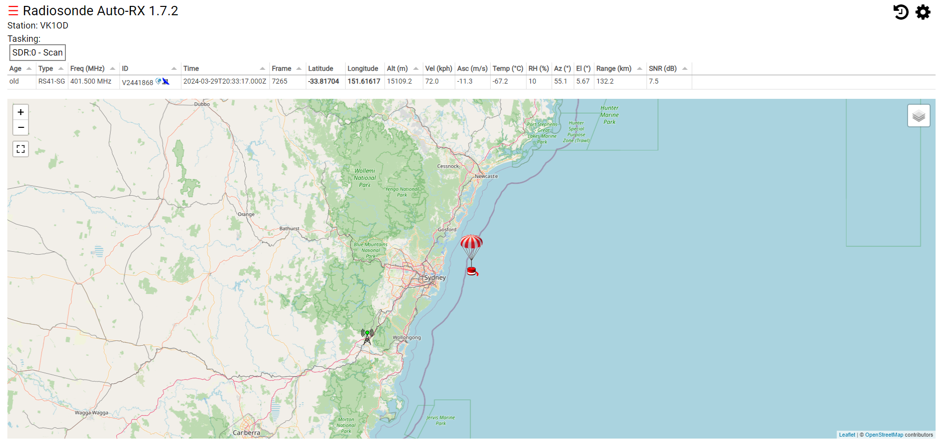
Radiosonde Auto-RX 1.7.2 is a software package for downloading data from a weather balloon.
Above is a screenshot from Radiosonde Auto-RX 1.7.2.
A friend has experienced problems where his RTL-SDR dongle stops working periodically. This is apparently a known problem if the power supply voltage is low.
This article documents current and voltage at the USB power jack on the RPi of:
RPi 3B+ running Radiosonde Auto-RX 1.7.2;
RTL-SDR v3 dongle on a 200mm USB extension cable; and
‘official’ RPi 3+ (5.1V 2.5A) power supply.
The RPi3B+ is a problem, it spews log messages when the supply falls much below 5V, and IIRC even if the voltage is withing the USB standards. That said, my understanding is that in this scenario, it is the RTL-SDR that may be the intolerant one.
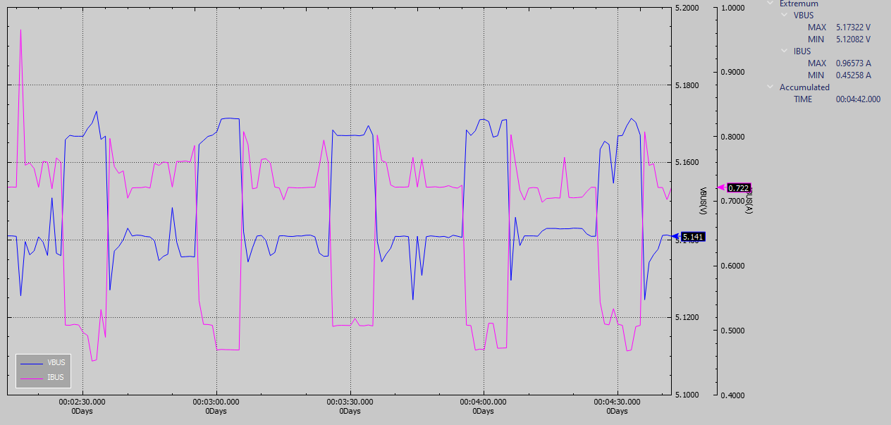
Above is a capture of voltage and current when the system is in the scanning mode. Periodically it launches a scan which drives system current up which causes a small sag in voltage.
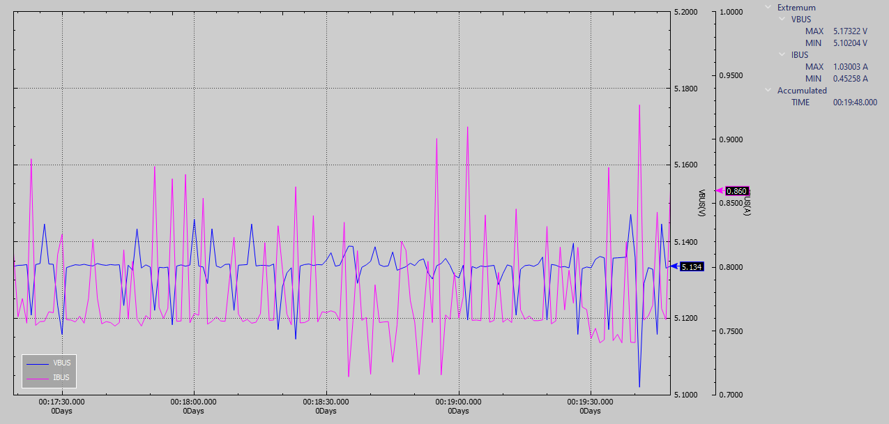
Above is a scan when a balloon is being decoded, quite a different current profile.
Note that the measurements relate to the hardware configuration described, and to some extent the software build on the RPi.
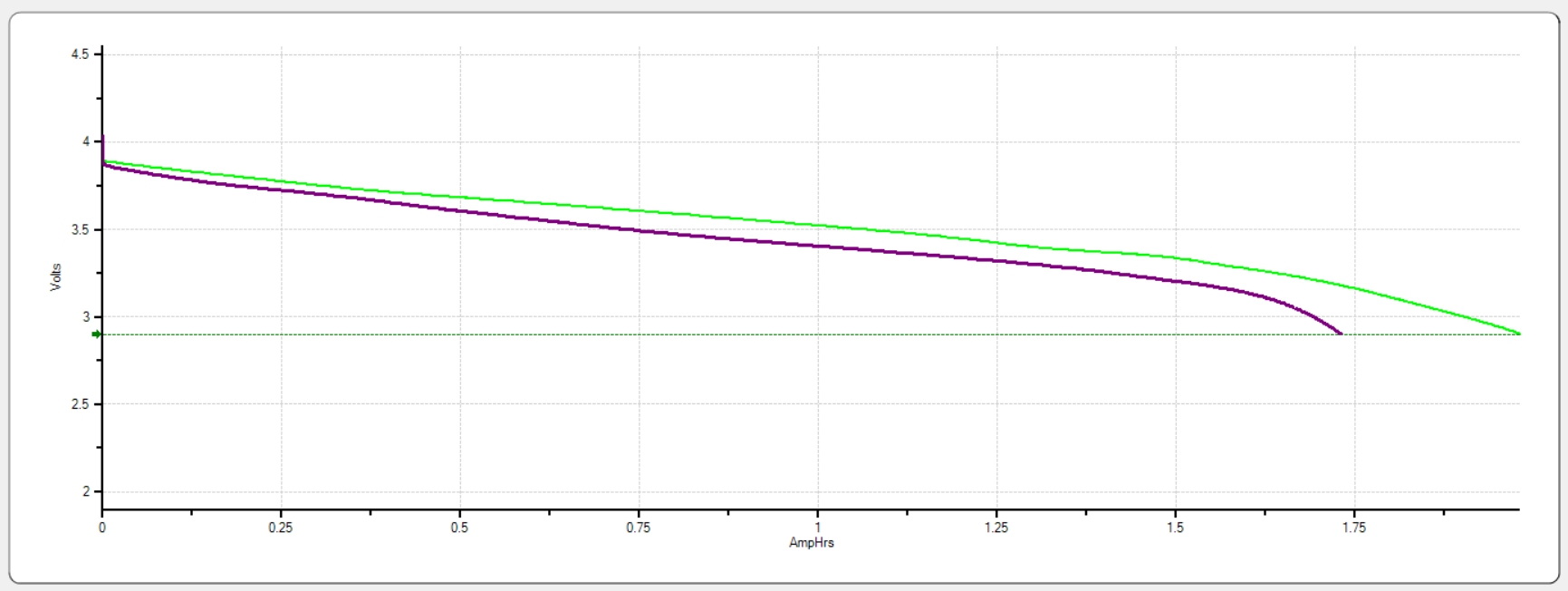
In Repack of Hikoki / Hitachi EBM315 battery pack (DB3DL2) I discussed the repack of a battery pack. At the same time I also ordered a no-name replacement 1.5Ah battery on Aliexpress for $25 incl shipping… with some reservation as most batteries I have purchased on Aliexpress have failed to deliver half of the rated capacity.
So, the battery arrived and I tested it, the purple trace above, and I was pleased to see that it exceeded the rated capacity a little.
So, I purchased another from the same seller, and it duly arrived, and to my surprise, it exceeded rated capacity by 30%.
Both batteries recharge properly on the Hitachi / Hikoki charger.
Time will tell whether they are good value. In any event, they use screws to hold the cap on so they can probably be repacked with good cells.
It was only through Sadguru Shree Aniruddha Bapu’s arrangement for us to be present as a support function for the “Old is Gold” distribution in remote villages that I had the chance to operate...
Well. Further to my previous post where all hope seemed to have gone out of the window I finally made progress today, but not the way I set out to.
First off, I pulled a Raspberry Pi 4 from another project and sat the CaribouLite HAT on it.
Next was a fresh installation of DragonOS. But this time it did open the ssh port – I’ve no idea why it did not before and note I am being unscientific here as I changed the Pi, but I am not going backwards.
Then, time for install.sh…
All seemed to go well but the software failed to compile completely. Searching on the errors I added #include <memory> to two source files, cariboulite/software/libcariboulite/src/CaribouLiteCpp.cpp and cariboulite/software/libcariboulite/src/CaribouLite.hpp. Stripping out all the ‘apt’s and ‘depmod’ from install.sh and running it again and the software compilation completed! I had already added and commented out the necessary lines in /boot/firmware/config.txt so a reboot was all that was needed to kick it into life. The driver was loaded – lsmod|smi showed this and also /proc/device-tree/hat now exists, both precursors to success according to the notes and YouTube videos.
Running sudo SoapySDRUtils –find showed the card, and, finally (!), running SoapySDRServer –bind and CubicSDR on the Mac mini finds the server on the Pi and I can tune to the local radio station.
Success, but that was a struggle. Mind you, I learned stuff at least!
I came across this via a post someone made somewhere – actually it might have been an email on a group. Anyway, with a tx/rx range top to 6GHz I thought, why not? It arrived quite quickly from Crowd Supply via Mouser with Crowd Supply charging the VAT but no other taxes on arrival.
I duly mounted it on a spare Raspberry Pi 3B with a fresh Bookworm 64 bit OS and followed the installation instructions at https://github.com/cariboulabs/cariboulite but I always got various errors and never got to a working system. The errors were mainly surrounding the SMI driver and the kernel headers. There seemed no way round this one, and thus no working system.
Following on from another complaint I downloaded and installed DragonOS, a 64 bit variant with lots of SDR utilities built in. Once installed, although the developer stated that ssh is available from first boot and does not need the usual empty ssh file it is not – the system does not open port 22 but does open the vnc port so I then had to find out which of my desktop systems has a vnc viewer as I never use it. When I found one and connected all it gave me was a blank screen. But guess what? Adding an empty ssh file onto the SD card worked, despite the advice!
Following the guidance from one user regarding getting the cariboulite to even install I did a complete upgrade / dist-upgrade cycle and then began the installation process. This time there were no errors about SMI or the kernel headers but there were fatal errors in the general build and no working system at the end.
After countless iterations, reading comments from other users, watching YouTube videos etc. I had to admit defeat and give up.
So there we are. On one hand it serves me right for not finding and reading all the issues before ordering this thing, but on the other given it costs money I rightly expect more, i.e. something that actually works rather than something that will sit in a box until maybe, one day the developer sorts the mess out. As it is I would compare it to the excellent SDRConnect and RSP SDR products which just work – this is the exact opposite!
In a nutshell, don’t bother with this card. But then, you never know, maybe the developer will sort the software and I will re-visit this post in a more positive light.
Update: there is a fork of the software detailed at https://github.com/cariboulabs/cariboulite/discussions/82 but following those instructions in a fresh Bookworm throws up the same kernel header errors and results in no SMI driver. So no go there. I tried the same in a fresh DragonOS – I must have been mistaken about the ned for the ssh file because I added this but DragonOS never opens the ssh port for me. So, no go there either!
All in all this has been a lesson in how to waste many hours for no gain. YMMV. There are a few other web pages with differing views and builds which I may try but as a product this is really, really poorly supported by the developer.
My second NinoTNC is built. The parts came today from Mouser in a huge box. I need to adjust the case a little to make it fit nicely but now I have this one I can go mobile and see how access to GB7RVB is. So far, no-one has connected (and yes, the antenna is still in the loft!)
I did find a TNC program for the Mac called KISSet which works fine once I remembered to put my callsign in! I wondered why it was sending data and GB7RVB’s TNC was receiving – no callsign. Twit. It worked fine after that.
I have a Tait TM8110 VHF transceiver that is destined for use on packet radio. This was sold as untested but appears to work fine. However, in testing I was concerned that the bench PSU I connected it to showed a current draw of 0A. The radio was making noise and, connected to the Bird and a dummy load was generating RF. Anyway, I programmed it with the various packet frequencies, power settings and ensured the bandwidth was 12.5kHz and tried it on air. It was working fine on both tx and rx. But still 0A draw. Hmmm.
I have two identical bench supplies, Lavolta BPS-305, 30V 5A units. One has a noisy fan so I use the other. I swapped to the noisy one and it shows reasonable current draws for rx and tx. And then the noisy fan decided not be noisy any more (still working though!) so perhaps the noise from this PSU was just it sulking from being ignored.
We’re still alive! November and December have been very busy months. In that short time I both decided to find a new job, found a new job, and started the new job. I’m back into doing what I love best: Fixing things, and writing things. I guess you could just say I’m wired that way. …
The PlutoSDR Rev C brings out both the transmit and receive channels. Thus, making it an even more capable device, especially for advanced RF stuff. A phased array is an advanced RF application that...