In his latest video, Matt from the TechMinds YouTube channel tests out an LHCP L-band helix feed designed for receiving Inmarsat satellites. Matt pairs the feed with an 85cm satellite dish, an L-band LNA, and an Airspy Mini.
The L-band helix feed comes from a small German engineering company called nolle.engineering. The feed is priced at 94.70 Euros (incl. VAT) (~$102 USD), plus shipping costs. It is a passive antenna so it needs to be combined with an LNA to be usable with a typical SDR.
In the video Matt shows that the reception with the LHCP helix + dish setup is better than expected. He also compares it to a previous test he did with a longer RHCP helix antenna also produced by nolle.engineering. The RHCP antenna is used to be used without a dish, however, as expected the SNR is less than the dish + small LHCP feed setup. Matt then shows some Inmarsat signals being decoded including STD-C and Aero voice.
Following on from my article about my QO-100 Satellite Ground Station Complete Build, this article goes into some detail on the Node-RED section of the build and how I put together my QO-100 Satellite Ground Station Dashboard web app.
The Node-RED project has grown organically as I used the QO-100 satellite over time. Initially this started out as a simple project to synchronise the transmit and receive VFO’s so that the SDR receiver always tracked the IC-705 transmitter.
Over time I added more and more functionality until the QO-100 Ground Station Dashboard became the beast it is today.
M0AWS QO-100 Ground Station Control Dashboard built using Node-RED.
Looking at the dashboard web app it looks relatively simple in that it reflects a lot of the functionality that the two radio devices already have in their own rights however, bringing this together is actually more complicated than it first appears.
Starting at the beginning I use FLRig to connect to the IC-705. The connection can be via USB or LAN/Wifi, it makes no difference. Node-RED gains CAT control of the IC-705 via XMLRPC on port 12345 to FLRig.
To control the SDR receiver I use GQRX SDR software and connect to it using RIGCTL on GQRX port 7356 from Node-RED. These two methods of connectivity work well and enables full control of the two radios.
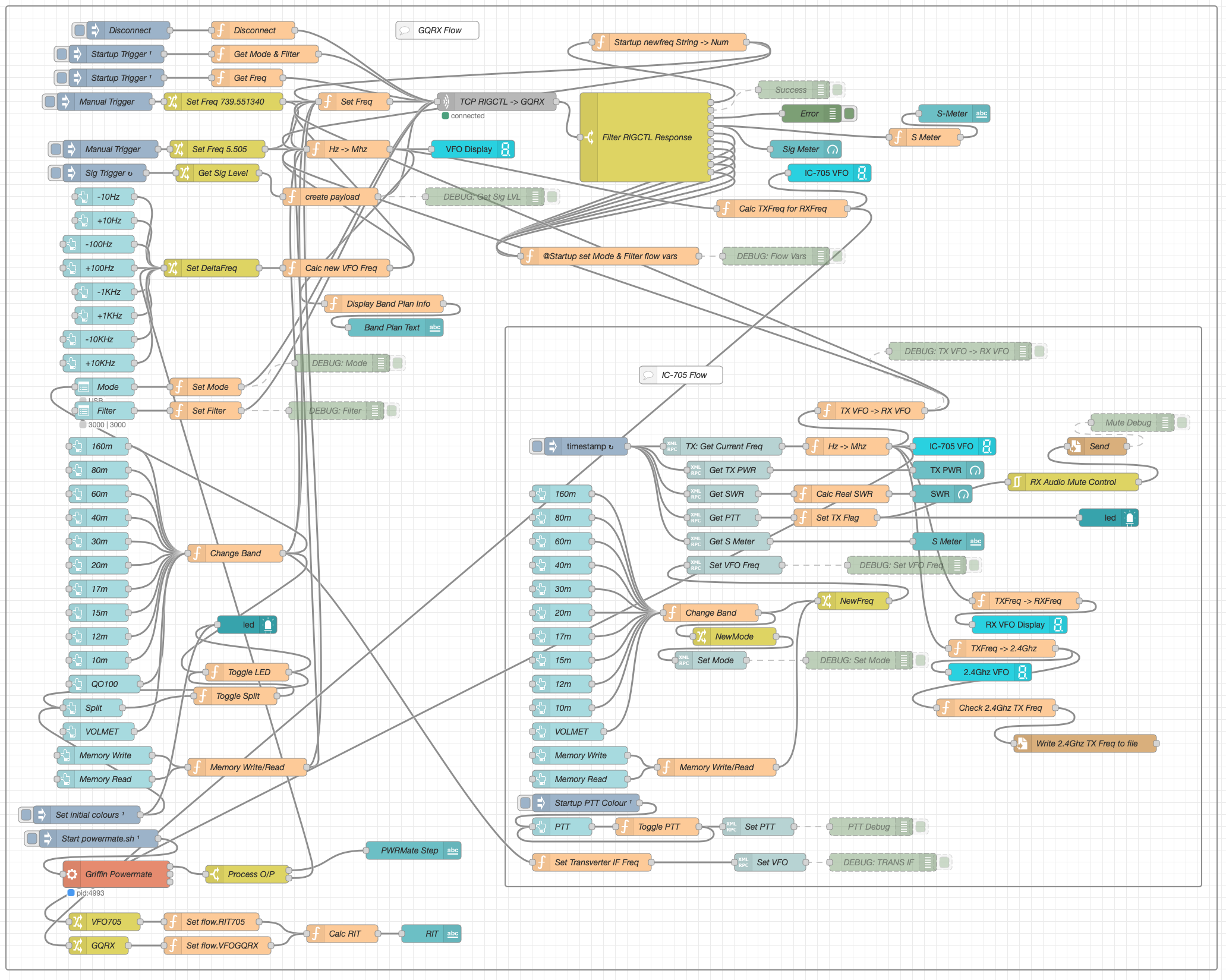
M0AWS Node-RED QO-100 Ground Station Dashboard Flow as of 12/06/24
The complete flow above looks rather daunting initially however, breaking it down into its constituent parts makes it much easier to understand.
There are two sections to the flow, the GQRX control which is the more complex of the two flows and the comparatively simple IC-705 section of the flow. These two flows could be broken down further into smaller flows and spread across multiple projects using inter-flow links however, I found it much easier from a debug point of view to have the entire flow in one Node-RED project.
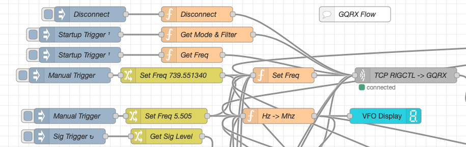
Breaking down the flow further the GQRX startup section (shown below) establishes communication with the GQRX SDR software via TCP/IP and gets the initial mode and filter settings from the SDR software. This information is then used to populate the dashboard web app.
M0AWS Node-RED QO-100 Ground Station Dashboard – GQRX Startup Flow
The startup triggers fire just once at initial startup of Node-RED so it’s important that the SDR device is plugged into the PC at boot time.
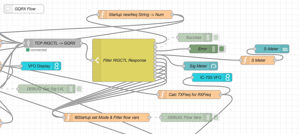
All the startup triggers feed information into the RIGCTL section of the GQRX flow. This section of the flow (shown below) passes all the commands onto the GQRX SDR software to control the SDR receiver.
M0AWS Node-RED QO-100 Ground Station Dashboard – GQRX RIGCTL Flow
The TCP RIGCTL -> GQRX node is a standard TCP Request node that is configured to talk to the GQRX software on the defined IP Address and Port as configured in the GQRX setup. The output from this node then goes into the Filter RIGCTL Response node that processes the corresponding reply from GQRX for each message sent to it. Errors are trapped in the green Debug node and can be used for debugging.
The receive S Meter is also driven from the the output of the Filter RIGCTL Response node and passed onto the S Meter function for formatting before being passed through to the actual gauge on the dashboard.
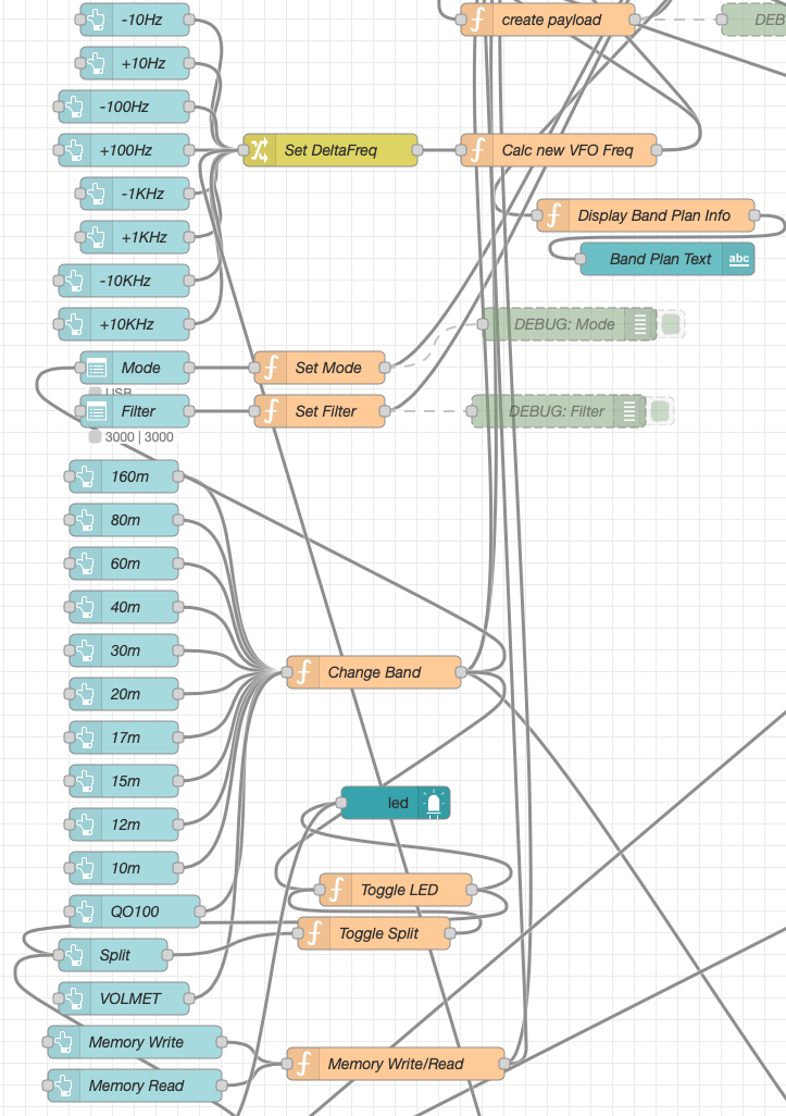
Continuing down the left hand side of the flow we move into the section where all the GQRX controls are defined.
M0AWS Node-RED QO-100 Ground Station Dashboard – GQRX Controls Flow
In this section we have the VFO step buttons that move the VFO up/down in steps of 10Hz to 10Khz. Each button press generates a value that is passed onto the Set DeltaFreq change node and then on to the Calc new VFO Freq function. From here the new VFO frequency is stored and passed onto the communications channel to send the new VFO frequency to the GQRX software.
The Mode and Filter nodes are simple drop down menus with predefined values that are used to change the mode and receive filter width of the SDR receiver.
Below are the HAM band selector buttons, each of these will use a similar process as detailed above to change the VFO frequency to a preset value on each of the HAM HF Bands.
The QO-100 button puts the transmit and receive VFO’s into synchro-mode so that the receive VFO follows the transmit VFO. It also sets the correct frequency in the 739Mhz band for the downlink from the LNB in GQRX SDR software and sets the IC-705 to the correct frequency in the 2m VHF HAM band to drive the 2.4Ghz up-converter.
The Split button allows the receive VFO to be moved away from the transmit VFO for split operation when in QO-100 mode. This allows for the receive VFO to be moved away so that you can RIT into slightly off frequency stations or to work split when working DXpedition stations.
The bottom two Memory buttons allow you to store the current receive frequency into a memory for later recall.
At the top right of this section of the flow there is a Display Band Plan Info function, this displays the band plan information for the QO-100 satellite in a small display field on the Dashboard as you tune across the transponder. Currently it only displays information for the satellite, at some point in the future I will add the necessary code to display band plan information for the HF bands too.
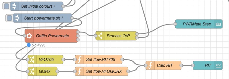
The final section of the GQRX flow (shown below) sets the initial button colours and starts the Powermate USB VFO knob flow. I’ve already written a detailed article on how this works here but, for completeness it is triggered a few seconds after startup (to allow the USB device to be found) and then starts the BASH script that is used to communicate with the USB device. The output of this is processed and passed back into the VFO control part of the flow so that the receive VFO can be manually altered when in split mode or in non-QO-100 mode.
M0AWS Node-RED QO-100 Ground Station Dashboard – Powermate VFO Flow
The bottom flows in the image above set some flow variables that are used throughout the flow and then calculates and sets the RIT value on the dashboard display.
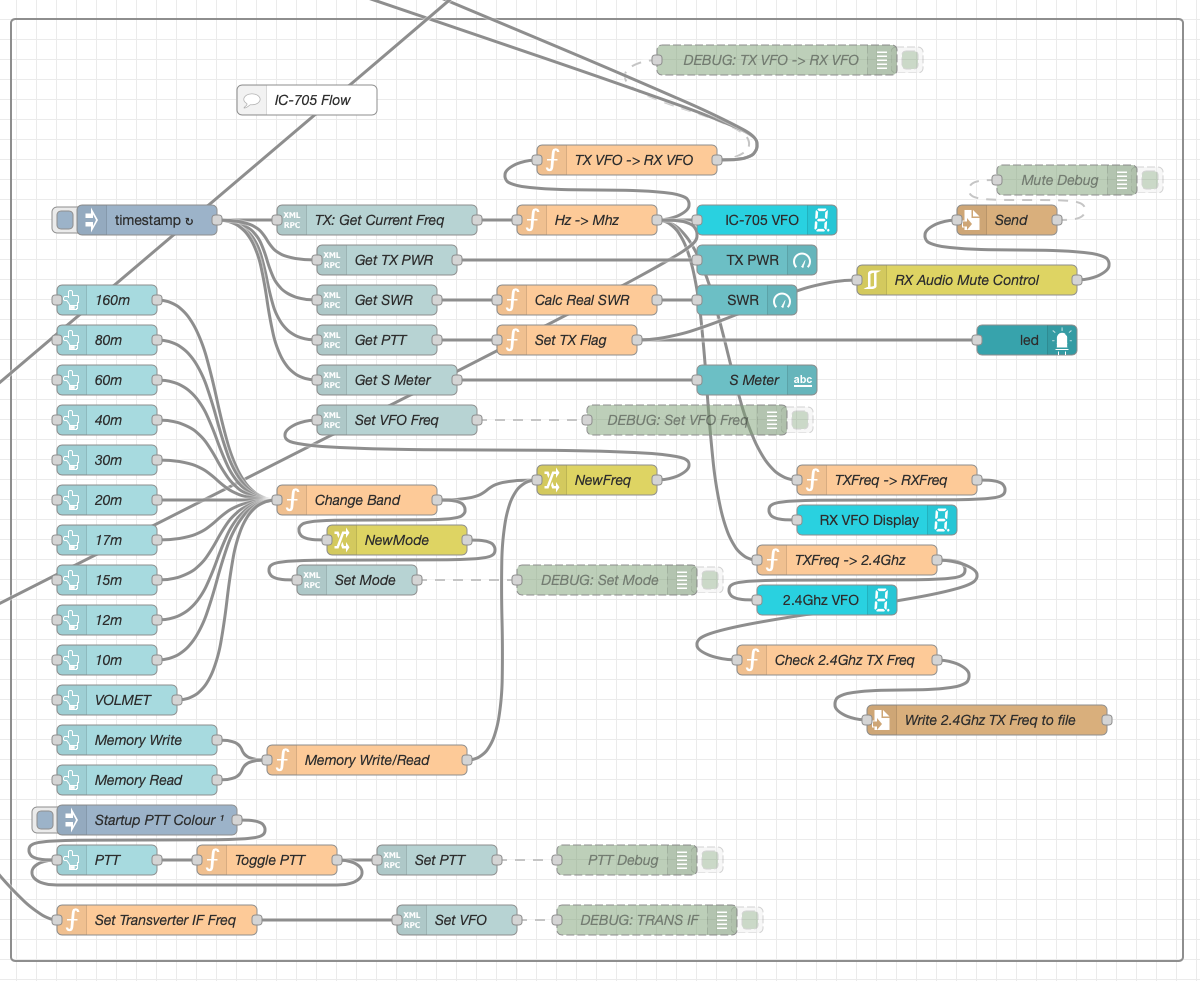
The final section of the flow is the IC-705 control flow. This is a relatively simple flow that is used to both send and receive data to/from the IC-705, process it and pass it on to the other parts of the flow as required.
M0AWS Node-RED QO-100 Ground Station Dashboard – IC-705 Control Flow
The IC-705 flow is started via the timestamp trigger at the top left. This node is nothing more than a trigger that fires every 0.5 seconds so that the dashboard display is updated in near realtime. The flow is pretty self explanatory, in that it collects the current frequency, transmit power, SWR reading, PTT on/off status and S Meter reading each time it is triggered. This information is then processed and used to keep the dashboard display up to date and to provide VFO tracking information to the GQRX receive flow.
On the left are the buttons to change band on the IC-705 along with a button to tune to the VOLEMT on the 60m band. Once again there two memory buttons to save and recall the IC-705 VFO frequency.
The Startup PTT Colour trigger node sets the PTT button to green on startup. The PTT button changes to red during transmit and is controlled via the Toggle PTT function.
At the very bottom of the flow is the set transverter IF Freq function, this sets the IC-705 to a preselected frequency in the 2m HAM band when the dashboard is switched into QO-100 mode by pressing the QO-100 button.
On the right of the flow there is a standard file write node that writes the 2.4Ghz QO-100 uplink frequency each time it changes into a file that is used by my own logging software to add the uplink frequency into my log entries automatically. (Yes I wrote my own logging software!)
The RX Audio Mute Control filter node is used to reduce the receive volume during transmit when in QO-100 full duplex mode otherwise, the operator can get tongue tied hearing their own voice 250ms after they’ve spoken coming back from the satellite. This uses the pulse audio system found on the Linux platform. The audio is reduced to a level whereby it makes it much easier to talk but, you can still hear enough of your audio to ensure that you have a good, clean signal on the satellite.
As I said at the beginning of this article, this flow has grown organically over the last 12 months and has been a fun project to put together. I’ve had many people ask me how I have created the dashboard and whether they could do the same for their ground station. The simple answer is yes, you can use this flow with any kind of radio as long as it has the ability to be controlled via CAT/USB or TCP/IP using XMLRPC or RIGCTL.
To this end I include below an export of the complete flow that can be imported into your own Node-RED flow editor. You may need to make changes to it for it to work with your radio/SDR but, it shouldn’t take too much to complete. If like me you are using an IC-705 and any kind of SDR controlled by GQRX SDR software then it’s ready to go without any changes at all.
I get quite a few emails from readers of my blog asking how my QO-100 satellite station is put together and so, I thought perhaps now is a good time to put together an article detailing the complete build.
My QO-100 satellite ground station is built around my little Icom IC-705 QRP transceiver, it’s a great little rig and is ideal for the purpose of driving a 2.4Ghz transverter/up-converter.
Of course all the software used for the project is Opensource and freely available on the internet.
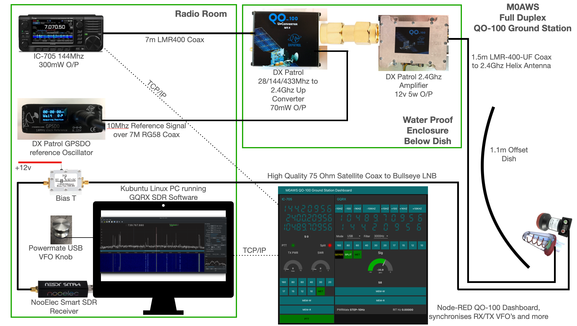
M0AWS QO-100 Ground Station Build Visual (Click to Enlarge)
The station comprises of the following building blocks:
QO-100 Ground Station Dashboard developed using Node-RED
LMR400-UF/RG58 Coax Cable
M0AWS QO-100 1.1m (110cm) off-set Dish with IceCone Helix antenna and Bullseye LNB.
To get a good clear view of the QO-100 satellite I have the dish mount 3.2m above the ground. This keeps it well clear of anyone walking past in the garden and beams the signal up at an angle of 26.2 degrees keeping well clear of neighbouring gardens.
The waterproof enclosure below the dish houses all the 2.4Ghz equipment so that the distance between the feed point and the amplifier are kept to a minimum.
The DXPatrol amplifier is spec’d to run at 28v/12w or 12v/5w, I found that running it at 28v produced too much output for the satellite and would cause the LEILA alarm on the satellite to trip constantly. Running the amp at 12v with a maximum of 5w output (average 2.5-3.5w) is more than enough for me to have a 5/9+10 signal on the transponder.
The large 1.1m dish gives me quite an advantage on receive enabling me to hear the very weak stations with ease compared to other stations.
2.4Ghz ground station enclosure ready for testing
The photo above shows the 2.4Ghz equipment mounted in the waterproof enclosure below the dish. This photo was taken during the initial build phase before I rewired it so, the amplifier is shown connected to the 28v feed. To rewire the amp to 12v was just a matter of removing the 28v converter and connecting the amp directly to the 12v feed instead. This reduced the output from a maximum of 12w down to a maximum of 5w giving a much better (considerate) level on the satellite.
It’s important to keep all interconnects as short as possible as at 2.4Ghz it is very easy to build up a lot of loss between devices.
For the connection from the IC-705 to the 2.4Ghz Up-Converter I used a 7m run of LMR-400 coax cable. The IC-705 is set to put out just 300mW on 144Mhz up to the 2.4Ghz converter and so it’s important to use a good quality coax cable.
Once again the output from the 2.4Ghz amplifier uses 1.5m of LMR-400-UF coax cable to feed up to the 2.2 turn Icecone Helix Antenna mounted on the dish. This keeps loss to a minimum and is well worth the investment.
Bullseye 10Khz High Stability Unversal Single LNB for 10.489-12.750Ghz
The receive path starts with a Bullseye LNB, this is a high gain LNB that is probably one of the best you could use for QO-100 operations. It’s fairly stable frequency wise but, does drift a little in the summer months with the high temperature changes but, overall it really is a very good LNB.
The 12v feed to the LNB is via the coax and is injected by the Bias-T device that is in the radio shack. This 12v feed powers the LNA and associated electronics in the LNB to provide a gain of 50-60dB.
Bias-T to inject 12v feed into the coax for the Bullseye LNB
From the Bias-T the coax comes down to the NooElec SmartSDR receiver. This is a really cheap SDR device (<£35 on Amazon) based on the RTL-SDR device but, it works incredibly well. I originally used a Funcube Dongle Pro+ for the receive side however, it really didn’t handle large signals very well and there was a lot of signal ghosting so, I swapped it out for the NooElec SDR and haven’t looked back since.
The NooElec SmartSDR is controlled via the excellent Opensource software GQRX SDR. I’ve been using GQRX SDR for some years now and it’s proven itself to be extremely stable and reliable with support for a good number of SDR devices.
To enhance the operation of the SDR device I have added a Griffin Powermate VFO knob to the build. This is an old USB device that I originally purchased to control my Flex3000 transceiver but, since I sold that many moons ago I decided to use it as a VFO knob in my QO-100 ground station. Details on how I got it working with the station are detailed in this blog article.
Having the need for full duplex operation on the satellite this complicates things when it comes to VFO tracking and general control of the two radios involved in the solution and so I set about creating a QO-100 Dashboard using the great Node-RED graphical programming environment to create a web app that simplifies the management of the entire setup.
M0AWS QO-100 ground Station Control Dashboard built using Node-RED.
The QO-100 Dashboard synchronises the transmit and receive VFO’s, enables split operation so that you can transmit and receive on different frequencies at the same time and a whole host of other things using very little code. Most of the functionality is created using standard Node-RED nodes. More info on Node-RED can be found on the Opensource.radio Wiki or from the menu’s above.
I’ll be publishing an article all about the QO-100 Dashboard in the very near future along with a downloadable flow file.
I’m extremely pleased with how well the ground station works and have had well in excess of 500 QSO’s on the QO-100 satellite over the last last year.
On June 25 the NOAA GOES-U weather satellite was successfully launched on a SpaceX Falcon 9 Heavy rocket. Once it reaches geostationary orbit, this will be a new weather satellite that RTL-SDR hobbyists can receive with an RTL-SDR dongle, satellite dish, and LNA.
From launch, it will take about two weeks for GOES-U to reach geostationary orbit and once it gets there it will be renamed to GOES-19. It is due to be positioned where GOES-16 currently is, and GOES-16 will become the redundant backup satellite. This positioning will make the satellite visible to those in North and South America.
GOES-16 is where GOES-19 will be positioned.
We are anxiously looking forward to the first images from GOES-19 received by hobbyists, but once positioned it will probably take several weeks to be tested and calibrated before hobbyists can receive any signals on L-band.
Over on X, @WeatherWorks posted a short video showing that the launch plume was visible from GOES-16.
A successful launch of @NOAA's GOES-U satellite yesterday. But was even cooler? It was seen from GOES-16! Check it out. It may be hard to see, but a cloud blips into view on satellite as the @SpaceX falcon heavy rocket as it lifts off from Cape Canaveral. #Space#SpaceX#GOESU… pic.twitter.com/e1s261y797
Thank you to 'Tuned Signal' (TS) for sharing his video with impressive production quality, detailing his story on how and why he became hooked on software-defined radio. TS notes how it all started with an Outernet receiver that he purchased, which came with an RTL-SDR dongle. From there he ended up purchasing higher end SDRs and learning more about the different types of signals he could receive.
If you're interested, check out some of his other videos on his YouTube channel which cover topics like how to receive train radios, how to listen to CB radio and more.
Paolo Romani (IZ1MLL) has recently released the 2024 version of his SDR# Big Book. The book is available for download on the Airspy downloads page, just scroll down to the title "SDR# Big Book" and choose your language. (At the time of this post only English and Italian are available in the 2024 edition, but multiple languages are available for the older guides).
Paolo writes that the book has been updated for the latest SDR# v1920 version, and now the editions will be labelled by date, instead of version number. He also writes that page 25 of the big book now includes information about the differences between RTL-SDR Blog V3 and V4 dongles.
Over on YouTube Matt from the Tech Minds YouTube channel has tested out NooElec's new 'FlyCatcher', which is an RTl-SDR ADS-B hat for the Raspberry Pi. The FlyCatcher has two RTL-SDRs built into it, each with it's own LNA and SAW filter. One SAW filter is tuned for 978 MHz UAT, and the other for 1090 MHz ADS-B.
The device also has buttons that allow you to bypass the LNA stage, and just use filtering, in case you have an external LNA. They appear to be using the Qorvo TQL9063 LNA chip, which has a built-in bypass.
In the video Matt tests out the FlyCatcher, but only on 1090 MHz as 978 MHz UAT is not used in his country. He shows how to set up the software on the Raspberry Pi and then shows some results.
A few people expressed interest in the HL2 that I mentioned a few weeks ago - two of those were CW ops who want to know how it does on that mode.To improve its performance on CW, I ordered the mod kit which converts the rig to a Plus model.The mod kit was sent out by WA2T the very day I ordered it but it arrived after we'd left for Iceland and has been with our neighbor since then. We are home
Many thanks to SWLing Post contributor, Frank, who writes: Hi, I am Frank SWL F14368, organizer of the SWL Contest 2024. I have written an article [about the use of WebSDRs]. Maybe you like to share on your nice website for SWL ? https://icomjapan.blogspot.com/2023/12/listen-world-for-free-on-your-computer.html My contest is open to listeners who use a Kiwi or […]
Over on his YouTube channel, Aaron, creator of DragonOS and WarDragon has uploaded a video showing how it is possible to decode Meshtastic with an RTL-SDR and GNU Radio project called Meshtastic_SDR.
If you weren't aware of it, Meshtastic is software that enables off-grid mesh network based communications and can run on cheap LoRa hardware. The mesh based nature of the system means that communications can be received over long distances, without any infrastructure, as long as there are sufficient Meshtastic nodes in an area that are able to route the message to the destination node. One example application of Meshtastic is to use it as a mesh-based text messaging system. This might be useful for teams of hikers, pilots, or skiiers who operate in remote areas without cell phone coverage.
In the video, Aaron shows how to install the Meshtastic GNU Radio software on DragonOS (Linux), and how to run the GNU Radio flowgraph and Python decoder script. Later in the video Aaron shows some test text messages being received by the software.
The Meshtastic_SDR project can also be used to transmit Meshtastic messages with an appropriate TX-capable SDR.
Back in 2019 we posted about the release of Artemis 3, an open-source multi-platform program that makes searching through the Signal Identification Wiki offline possible and easy to do.
Recently Artemis 4 has been released which is an entire rewrite of the code, resulting in some substantial improvements, and paving the way for future features like machine learning based identification. Author Marco Dalla Tiezza writes:
Artemis was initially designed to provide an offline solution for consulting the library of signals provided by the community on sigidwiki, but the database was formerly a simple .csv with all its limitations. Now the database is a proper relational sqlite which is much easier handled and offers many other possibilities like: additional fields (for example, each frequency of a signal can contain a description and this is true for every single parameter), faster db operations (for example, filtering signals is done by a simple query), increased extensibility due to the fact that new fields/parameters can be introduced in the future or by the user itself.
The only searchable database with Artemis 3 was the Sigid wiki database.Now, with Artemis 4, users can create their own custom databases, enter an arbitrary number of signals and parameters, attach documents or any useful information, and export it by sharing it with their friends.
The documentation has been completely revised to be as clear as possible and to be able to take the user from installation to advanced use of the program by giving instructions on how they can contribute to the project. DOCUMENTATION
As usual, the program provides a real-time interface to be able to track space weather in near real-time, but now this module is more focused on RF propagation such as meteor scatter, EME, sporadic E, aurora spots, DRAP, aurora forecasts and many more (we are actively adding useful descriptors).
Artemis 4 now relies on the PySide 6 graphics framework, which not only allows for a modern and newer, user-customizable GUI but also allows for less use of third-party libraries to run the program.
Given the flexibility and especially the modularity of the new software, it is very likely that signal analysis functions will be introduced in the future (such as automatic recognition of signals via machine learning/neural network or simpler ones like FFT for obtaining ACF from an audio file, etc.)
The homepage of the project (https://www.aresvalley.com) as been updated as well and there you can see some screenshots or directly download the software to give it a try.
If you weren't aware, the Signal Identification Wiki (sigidwiki) is our sister site, which we started a few years ago to collect and catalog various types of signals that an SDR user might see and hear on the airwaves. The idea is that a user could search the database to learn about and identify unknown signals. Over time it has grown significantly, now over 500 known signals with both waterfall images and sound samples available in the database. We have since handed over the operation of the Wiki to the community, with Carl Colena taking on the lead.
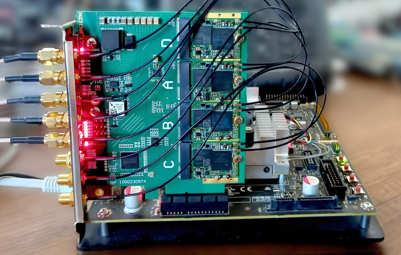
Thank you to creators Sergey and Andrew who have submitted news about their upcoming software defined radio called 'xMASS SDR'. xMASS will be a SDR with 8 RX and 8 TX channels, with a max sample rate of 60 MSPS per 8 channels, or 100 MSPS per 4 channels, and a frequency range of 30 - 3800 MHz.
The board comes in a modular PCIe form factor, with 4x FPGAs, and GPS/PPS clock sync input. The system is designed in mind for 4G/5G applications but should be useful for other applications too.
xMASS SDR will be crowd-funded on CrowdSupply, and they note that they expect to launch the campaign soon. So if you are interested, sign up for email updates on their CrowdSupply page.
Sergey and Andrew write:
We’re creators (Sergey Kostanbaev and Anrew Avtushenko) of the M.2 uSDR board that we successfully crowdsourced a year ago. Now we want to share our new invention called xMASS SDR, a modular, high-performance MIMO transceiver. It has 8 RX and 8 TX channels that can be synchronized for directional finding, beamforming and more applications. Each SDR module, called xSDR, is based on the LMS7002M chip and can deliver 2 RX and 2 TX channels. Like uSDR, xSDR shares the same form factor and M.2 pinout and both use the same open-source software and gateware stack.
xMASS SDR is ideal for 4G/5G but can be interesting among academic, industrial and advanced hobbyists.
The xMASS SDR board connected via PCIe on a motherboard.The xMASS SDR board with 4x modules by itself.
Welcome back to Sarah from the SignalsEverywhere YouTube channel who has recently returned to producing videos from a hiatus. In her latest video, Sarah shows off her new OP25 Mobile Control Head Android App which allows you to implement a full P25 digital radio scanner at a fraction of the cost of a commercial digital scanner. In the past, Sarah had released a similar application written for the Raspberry Pi but has decided to shift her focus to writing an equivalent Android app that is less clunky and can be deployed for a lower cost.
The app controls and displays information from the OP25 software that runs on a Raspberry Pi with RTL-SDR connected. It works by using a server application on the Raspberry Pi that manipulates the OP25 instance and its configuration files.
Sarah writes:
The application is a wrapper for OP25 that uses a raspberry pi and an android device to provide users with a mobile control head for their OP25 P25 scanner setup. Currently it's just a basic application but I'll be adding features like automatic site switching, etc.
Jay has also thought about cooling, allowing for space between the two dongles, and adding vent holes. He has also ensured that the SMA ports on the dongles are protected while allowing space to hand-tighten the connectors.
Jay writes that he has tested his enclosure with RTL-SDR Blog V4 units, but given that the dimensions of the V3 (and V2) are the same, it will work for those units too.
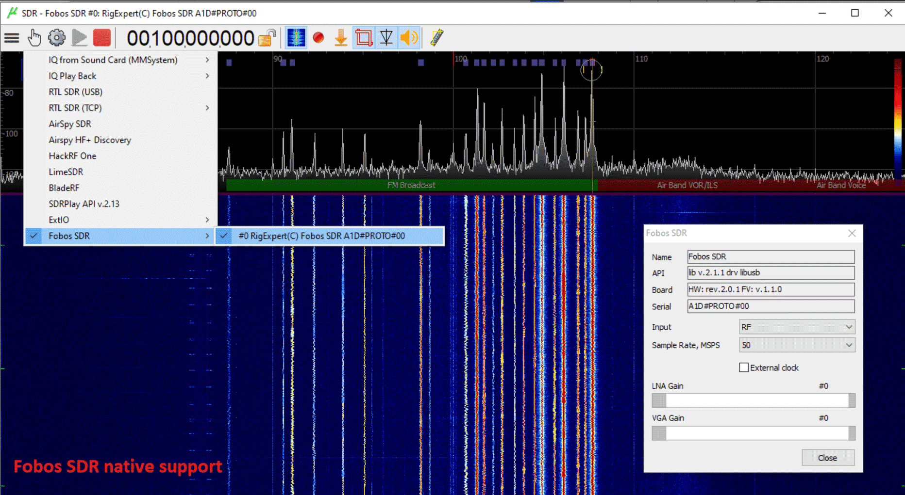
Thank you to Viol for writing in and letting us know that his uSDR software has recently been updated to V1.7.0. The uSDR software (not to be confused with the unrelated uSDR hardware) is a lightweight general-purpose multimode program for Windows that supports the RTL-SDR, Airspy, BladeRF, HackRF, LimeSDR, and other SDR radios.
Viol highlights the latest features added in the 1.7.0 update below:
Fobos SDR frontend native support, the very new SDR from RigExpert
bladeRF API v2.5.0 support, oversampling mode up to 122.88 MHz sample rate (do not forget to update FX3 firmware)
advanced IQ playback mode, precise timing and streaming
improved DSP routines and memory management, minimized CPU load
excellent ruler tool for spectrum frequency and amplitude measurements
uSDR Updated to Version 1.7.0. Images shows FobosSDR support.