Many thanks to SWLing Post contributor, Frank, who writes: Hi, I am Frank SWL F14368, organizer of the SWL Contest 2024. I have written an article [about the use of WebSDRs]. Maybe you like to share on your nice website for SWL ? https://icomjapan.blogspot.com/2023/12/listen-world-for-free-on-your-computer.html My contest is open to listeners who use a Kiwi or […]
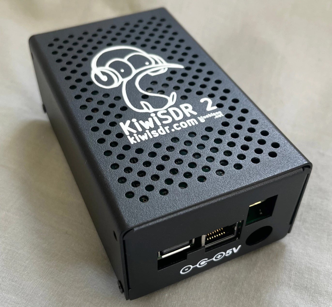
Earlier this year the KiwiSDR 2 became available for purchase and began shipping out to customers. The KiwiSDR 2 is an upgraded version of the original KiwiSDR with the main upgrades being an enhanced RF front end and the addition of a digital attenuator.
Over on the Tech Minds YouTube channel, Matt received his KiwiSDR 2 and uploaded a review and demonstration of the product. In the video, Matt shows the external ports of the KiwiSDR and discusses the differences between the KiwiSDR 2 and the original version. Matt goes on to show how to set up the KiwiSDR 2 and shows it receiving through it's web-based receiving software.
KiwiSDR is a 14-bit wideband RX-only HF software-defined radio created by John Seamons (ZL/KF6VO). The KiwiSDR has up to 32 MHz of bandwidth, so it can receive the entire 10 kHz - 30 MHz VLF/LF/MW/HF spectrum all at once. Other than the specifications, the main interesting feature about the KiwiSDR is that it is designed to be operated entirely as an online web-based SDR which is accessed over a network connection. Owners can optionally share their KiwiSDRs online with anyone who wants to access it, which also allows for interesting distributed applications, such as TDoA direction finding, which allows users to pinpoint the location of unknown HF transmissions such as numbers stations.
Back in August 2023 we posted about the pre-announcement of the KiwiSDR 2, an upgraded version of the original KiwiSDR. Most of the upgrades are minor or due to some chips becoming EOL. The main upgrades are an enhanced RF front end and the addition of a digital attenuator. One change is also the manufacturing country. Instead of being manufactured in China, the KiwiSDR 2 is now manufactured in New Zealand.
The new KiwiSDR 2 can be purchased from kiwisdr.nz. Pricing is $648 NZD ($395 USD) for the full KiwiSDR 2 cape + Beaglebone and enclosure set. The cape by itself is also available for $484 NZD ($295 USD). Currently the second production run is selling, and a third production run is in progress.
Previously the original KiwiSDR sold for $299 USD. Considering inflation, component changes and additions, and the change to a more expensive country to manufacture in, the price increase seems reasonable.
KiwiSDR is a 14-bit wideband RX only HF software defined radio created by John Seamons (ZL/KF6VO). The KiwiSDR has up to 32 MHz of bandwidth, so it can receive the entire 10 kHz - 30 MHz VLF/LF/MW/HF spectrum all at once. Other than the specifications, the main interesting feature about the KiwiSDR is that it is designed to be operated entirely as an online web based SDR which is accessed over a network connection. Owners can optionally share their KiwiSDRs online with anyone who wants to access it, which also allows for interesting distributed applications, such as TDoA direction finding, which allows users to pinpoint the location of unknown HF transmissions such as numbers stations.
Here is my improved PTT muting circuit! I've seen at least a few PTT muting circuits for Web radios, but this one I helped design and so I'll name it the "MuteMate" Basically what it does is mute the computer...
As a sort of follow-up to the previous posting about the RX-888 (Mk2) I decided to make some measurements to help characterize the gain and attenuation settings.
The RX-888 (Mk2) has two mechanisms for adjusting gain and attenuation:
The PE4312 attenuator. This is (more or less) right at the HF antenna input and it can be adjusted to provide up to 31.5dB of attenuation in 0.5dB steps.
The AD8370 PGA. This PGA (Programmable Gain Amplifier) can be adjusted to provide a "gain" from -11dB to about 34dB.
Note:
While this blog posting has specific numbers related to the RX-888 (Mk2), its general principles apply to ALL receivers - particularly those operating as "Direct Sampling" HF receivers. A few examples of other receivers in this category include the KiwiSDR and Red Pitaya - to name but two.
Other article RX-888 articles:
RX-888 Thermal issues: I recently posted another article about the RX-888 (Mk2) discussing the thermal properties of its mechanical construction - and ways to improve it to maximize reliability and durability. You can find that article here: Improving the thermal management of the RX-888 (Mk2) - link.
Using an external clock with the RX-888: The 27 MHz external clock input to the RX-888 is both fragile and fickle. To learn a bit more about how to reliably clock an RX-888 from an external source, read THIS article.
* * * * *
Taking measurements
To ascertain the signal path properties of an RX-888 (Mk2) I set its sample rate to 64 Msps and using both the "HDSDR" and "SDR Radio" programs (under Windows - because it was convenient) and a a known-accurate signal generator (Schlumberger Si4031) I made measurements at 17 MHz which follow:
Gain setting (dB)
Noise floor (dBm/Hz)
Noise floor (dBm in 500Hz)
Apparent Clipping level (dBm)
-25
-106
-79
>+13dBm
+0
-140
-113
+3
+10
-151
-124
-8
+20
-155
-128
-18
+25
-157
-130
-23
+33
-158
-131
-31
Figure 1: Measured performance of an RX-888 Mk2. Gain mode is "high" with 0dB attenuation selected.
For convenience, the noise floor is shown both in "dBm/Hz" and in dBm in a 500 Hz bandwidth - which matches the scaling used in the chart below. As the programs that I used have no direct indication of A/D converter clipping, I determined the "apparent" clipping level by noting the amplitude at which one additional dB of input power caused the sudden appearance of spurious signals. Spot-checking indicated that the measured values at 17 and 30 MHz were within 1 dB of each other on the unit being tested.
Determining the right amount of "gain"
It should be stated at the outset that most of the available range of gain and attenuation provided by the RX-888's PE4312 step attenuator and AD8370 variable gain amplifier are completely useless to us. To illustrate this point, let's consider a few examples.
Consider the chart below:
Figure 2: ITU chart showing various noise environments versus frequency.
This chart - from the ITU - shows predicted noise floor levels - in a 500 Hz bandwidth - that may be expected at different frequencies in different locations. Anecdotally, it is likely that in these days of proliferating switch-mode power supplies that we really need another line drawn above the top "Residential" curve, but let's be a bit optimistic and presume that it still holds true these days.
Let us consider the first entry in Figure 1 showing the gain setting of 0dB. If we look at the "Residential" chart, above, we see that the curve at 30 MHz indicates a value very close to the -113dBm value in the "dBm in 500 Hz" column. This tells us several things:
Marginal sensitivity. Because the noise floor of the RX-888 (Mk2) and that of our hypothetical RF environment are very close to each other, we may not be able to "hear" our noise floor at 30 MHz (e.g. the 10 meter amateur band). One would need to do an "antenna versus no antenna" check of the S-meter/receiver to determine if the former causes an increase in signal level: If not, additional gain may be needed to be able to hear signals that are at the noise floor.
More gain may not help. If we do perform the "antenna versus no antenna" test and see that with the antenna connected we get, say, an extra S-unit (6dB) of noise, we can conclude that under those conditions that more gain will not help in absolute system sensitivity.
Thinking about the above two statements a bit more, we can infer several important points about operating this or any receiver in a given receive environment:
If we can already "hear" the noise floor, more gain won't help. In this situation, adding more gain would be akin to listening to a weak and noisy signal and expecting that increasing the volume would cause the signal to get louder - but not the noise.
More gain than necessary will reduce the ability of the receiver to handle strong signals. The HF environment is prone to wild fluctuations and signals can go between well below the local noise floor and very strong, so having any more gain that you need to hear your local noise floor is simply wasteful of the receiver's signal handling capability. This fact is arguably more important with wide-band, direct-sampling receivers where the entire HF spectrum impinges on the analog-to-digital converter rather than a narrow section of a specific amateur band as is the case in "conventional" analog receivers.
Let us now consider what might happen if we were to place the same receiver in an ideal, quiet location - in this case, let's look at the "quiet rural" (bottom line) on the chart in Figure 2.
Again looking at the value at 30 MHz, we see that our line is now at about -133dBm (in 500 Hz) - but if we have our RX-888 gain set at 0 dB, we are now ((-133) - (-113) = ) 20 dB below the noise floor. What this means is that a weak signal - just at the noise floor - is more than 3 S-units below the receiver sensitivity. This also means that a receiver that may have been considered to be "Okay" in a noisy, urban environment will be quite "deaf" if it is relocated to a quiet one.
In this case we might think that we would simply increase our gain from 0 dB to +33dB - but you'll notice that even at that setting, the sensitivity will be only -131dBm in 500 Hz - still a few dB short of being able to hear the noise in our "antenna versus no antenna" test.
Too much gain is worse than too little!
At this point I refer to the far-right column in Figure 1 that shows the clipping level: With a gain setting of +33dBm, we see that the RX-888 (Mk2) will overload at a signal level of around -31dBm - which translates to a signal with a strength a bit higher than "S9 + 40dB". While this sound like a strong signal, remember that this signal level is the cumulative TOTAL of ALL signals that enter the antenna port. Thinking of it another way, this is the same as ten "S9+30dB" signals or one hundred "S9+20dB" signals - and when the bands are "open," there will be many times when this "-31dBm" signal level is exceeded from strong shortwave broadcast signals and lightning static.
In the case of too-little gain, only the weakest signals, below the receiver's noise floor will be affected - but if the A/D converter in the receiver is overloaded, ALL signals - weak or strong - are potentially disrupted as the converter no longer provides a faithful representation of the applied signal. When the overload source is one or more strong transmissions, a melange of all signals present is smeared throughout the receive spectrum consisting of many mixing products, but if the overload is a static crash, the entire receive spectrum can be blanked out in a burst of noise - even at frequencies well removed from the original source of static.
Most of the adjustment range is useless!
Looking carefully at Figure 1 at the "noise floor" columns, you may notice something else: Going from a gain of 0 dB to 10 dB, the noise floor "improves" (is lower) by about the same amount - but if you go from 25 dB gain to 33 dB gain we see that our noise floor improves by only 1 dB - but our overload threshold changes by the same eight dB as our gain increase.
What we can determine from this is that for practical purposes, any gain setting above 20 dB will result in a very little receiver sensitivity improvement while causing a dramatic reducing in the ability of the receiver to handle strong signals.
Based on our earlier analysis in a noise "Urban" environment, we can also determine that a gain setting lower than 0 dB will also make our receiver too-insensitive to hear the weakest signals: The gain setting of -25dB shown in Figure 1 with a receive noise floor of -79dBm (500 Hz) - which is about S8 - is an extreme example of this.
Up to this point we have not paid any attention to the PE4312 attenuator as all measurements were taken with this set to minimum. The reason for this is quite simple: The noise figure (which translates to the absolute sensitivity of a receiver system) is determined by the noise generation of all of the components. As reason dictates, if you have some gain in the signal path, the noise contribution of the devices after the gain have lesser effects - but any loss or noise contribution prior to the gain will directly increase the noise figure.
Note:
For examples of typical HF noise figure values, see the following articles:
Based on the articles referenced above, having a receiver system with a noise figure of around 15dB is the maximum that will likely permit reception at the noise floor of a quiet 10 meter location. If you aren't familiar with the effects of noise figure - and loss - in a
receive signal path, it's worth playing with a tool like the Pasternack Enterprises Cascaded Noise Figure Calculator (link) to get a "feel" of the effects.
I do not have the ability to measure the precise noise figure of the RX-888 (Mk2) - and if I did do so, I would have to make such a measurement using the same variety of configurations depicted in Figure 1 - but we can know some parameters about the worst-case:
Bias-Tee: Estimated insertion loss of 1dB
PE4312: Insertion loss of 1.5dB at minimum attenuation
RF Switch (HF/VHF): 1dB loss
50-200 Ohm transformer: 1dB loss
AD8370 Noise figure: 8dB (at gain of 20dB)
The above sets the minimum HF floor noise figure of the RX-888 (Mk2) at about 12.5dB with an AD8370 gain setting of 20dB - but this does not include the noise figure of the A/D converter itself - which would be difficult to measure using conventional means.
On important aspect about system noise figure is that once you have loss in a system, you cannot recover sensitivity - no matter how much gain or how quiet your amplifier may be! For example, if you have a "perfect" 20 dB gain amplifier with zero noise, if you place a 10 dB attenuator in front of it, you have just turned it into an amplifier with 10 dB noise figurewith 10dB gain and there is nothing that can be done to improve it - other than get rid of the loss in front of the amplifier.
Similarly, if we take the same "perfect" amplifier - with 20dB of gain - and then cascade it with a receiver with a 20dB noise figure, the calculator linked above tells us that we now have a systemnoise figure of 3 dB since even with 20dB preceeding it, our receiver still contributes noise!
If we presume that the LTC2208 A/D converter in the RX-888 has a noise figure of 40dB and no gain (a "ballpark" value assuming an LSB of 10 microvolts - a value that probably doesn't reflect reality) our receive system will therefore have a noise figure of about 22dB.
What this meansis that in most of the ways that matter, the PE4312 attenuator is not really very useful when the RX-888 (Mk2) is being used for reception of signal across the HF spectrum, in a relatively quiet location on an antenna system with no additional gain.
Where is the attenuator useful?
From the above, you might be asking under what conditions would the built-in PE4312 attenuator actually be useful? There are two instances where this may be the case - and this would be applied ONLY if you have been unable to resolve overload situations by setting the gain of the AD8370 lower.
In a receive signal path with a LOT of amplification. If your receive signal path has - say - 30dB of amplification (and if it does, you might ask yourself "why?") a moderate amount of attenuation might be helpful.
In a situation where there are some extremely strong signals present. If you are near a shortwave or mediumwave (AM broadcast) transmitter that induces extremely strong signals in the receiver that cause intractable overload, the temporary use of attenuation may prevent the receiver from becoming overloaded to the point of being useless - but such attenuation will likely cause the complete loss of weaker signals. In such a situation, the use of directional antennas and/or frequency-specific filtering should be strongly considered!
Improving sensitivity
Returning to an earlier example - our "Quiet Rural" receive site - we observed that even with the gain setting of the RX-888 (Mk2) at maximum, we would still not be able to hear our local noise floor at 30 MHz - so what can be done about this?
Let us build on what we have already determined:
While sensitivities is slightly improved with higher gain values, setting the gain above 20dB offers little benefit while increasing the likelihood of overload.
In a "Quiet Rural" situation, our 30 MHz noise floor is about -133dBm (500 Hz BW) which means that our receiver needs to attain a lower noise floor than this: Let's presume that -136dBm (a value that is likely marginal) is a reasonable compromise.
With a "gain" setting of 20dB we know that our noise floor will be around -128dBm (500 Hz) and we need to improve this by about 8 dB. For straw-man purposes, let's presume that the RX-888 (Mk2) at a gain setting of 20dB has a noise figure of 25dB, so let's see what it takes for an amplifier that precedes the RX-888 (Mk2)to lower than to 17dB or so using the Pasternak calculator above:
10dB LNA with 7 dB noise figure: This would result in a system noise figure of about 16 dB - which should do the trick.
Again, the above presumes that there is NO loss (cable, splitters, filtering) preceding the preamplifier. Again, the presumed noise figure of 25dB for the RX-888 (Mk2) at a gain setting of 20 is a bit of a "SWAG" - but it illustrates the issue.
Adding a low-noise external amplifier also has another side-effect: By itself, with a gain setting of +33, the RX-888 (Mk2)'s overload point is -31dBm, but if we reduce the gain of the RX-888 to 20dB the overload drops to -18dBm - but adding the external 10dB gain amplifier will effectively reduce the overload to -28dBm, but this is still 5 dB better than if we had turned the RX-888's gain all of the way up!
Taking this a bit further, let's presume that we use, instead, an amplifier with 3dB noise figure and 8 dB gain: Our system noise figure is now about 17dB, but our overload point is now -26dBm - even better!
The RX-888 is connected to a (noisy) computer!
Adding appropriate amounts of external gain has an additional effect: The RX-888 (and all other SDRs) are computer/network connected devices with the potential of ingress of stray signals from connected devices (computers, network switches, power supplies, etc.). The use of external amplifiers can help override (and submerge) such signals and if proper care is taken to choose the amount of gain of the external amplification and properly choose gain/attenuation settings within the receiver, superior performance in terms of sensitivity and signal-handling capability can be the result.
Additional filtering
Only mentioned in passing, running a wideband, direct-sampling receiver of ANY type (be it RX-888, KiwiSDR, Red Pitaya, etc.) connected to an antenna is asking a lot of even 16 bits of conversion! If you happen to be in a rather noisy, urban location, the situation is a bit better in the sense that you can reduce receiver gain and still hear "everything there is to hear" - but if you have a very quiet location that requires extra gain, the same, strong signals that you were hearing in the noisy environment are just as strong in the quiet environment.
Here are a few suggestions for maximizing performance under the widest variety of situations:
Add filtering for ranges that you do not plan to cover. In most cases, AM band (mediumwave) coverage is not needed and may be filtered out. Similarly, it is prudent to remove signals above that in which you are interested. For the RX-888 (Mk2), if you run its sampling rate at just 65 MHz or so, you should install a 30 MHz low-pass filter to keep VHF and FM broadcast signals out.
Add "window" filtering for bands of interest. If you are interested only in amateur radio bands, there are a lot of very strong signals outside the bands of interest that will contribute to overload of the A/D converter. It is possible to construct a set of filters that will pass only the bands of interest - but this does not (yet?) seem to be a commercial product. (Such a product may be available in the near future - keep a lookout here for updates.)
Add a "shelving" filter. If you examine the graph in Figure 2 you will notice that as you go lower in frequency, the noise floor goes UP. What this means is that at lower frequencies, you need less receiver sensitivity to hear the signals that are present - and it also means that if you increasingly attenuate those lower frequencies, you can remove a significant amount of RF energy from your receiver without actually reducing the absolute sensitivity. A device that does just this is described in a previous blog article "Revisiting the limited-attenuation high-pass filter - again (link)". While I do not offer such a filter personally, such a device - along with an integrated 30 MHz low-pass filter - may be found at Turn Island Systems- HERE.
Conclusions:
The best HF weak-signal performance for the RX-888 (Mk2) will occur with the receiver configured for "High" gain mode, 0 dB attenuation and a gain setting of about 20dB. Having said this, you should always to the "antenna versus no antenna" test: If you see more than 6-10dB increase in the noise level at the quietest frequency, you probably have too much gain. Conversely, if you don't see/hear a difference, you probably need more gain - taking care in doing so.
For best HF performance of this - or any other wideband, direct-sampling HF SDR (RX-888, KiwiSDR, Red Pitaya, etc.) additional filtering is suggested - particularly the "shelving" filter described above.
In situations where the noise floor is very low (e.g. a nice, receive quiet location) many direct-sampling SDRs (RX-888, KiwiSDR, Red Pitaya) will likely need additional gain to "hear" the weaker signals - particularly on the higher HF bands. While some of these receivers offer onboard gain adjustment, the use of external high-performance (low-noise) amplification (along with filtering and careful adjustment of the devices' gain adjustments) will give improved absolute sensitivity while helping to preserve large-signal handling capability.
Because the RX-888 is a computer-connected device, there will be ingress of undesired signals from the computer and the '888's built-in circuitry. The use of external amplification - along with appropriate decoupling (e.g. common-mode chokes on the USB cable and connecting coaxial cables) can minimize the appearance of these signals.
This morning I ran a net from my portable station in Cullman, Alabama using a combination of my transceiver for transmitting and KiwiSDR and WebSDR for receiving. My portable station is an Icom 7300 running into a G5RV antenna up...
At the Northern Utah WebSDR (link) we run a number of KiwiSDR receivers. These receivers, which are inherently broadband (10 kHz to 30 MHz) allow a limited number of users to tune across the bands, allowing reception on frequencies that are not covered by the WebSDR servers.
At present there are six of these receivers on site: Three are connected to the TCI-530 Omnidirectional antenna (covering 630-10 meters - 2200 meters is included via a separate E-field whip), two are on the east-pointing log-periodic beam antenna (which overs 40-10 meters) and the newest is connected to the northwest-pointing log-periodic beam antenna (which covers 30-10 meters).
Figure 1: Power supply in a PC case! The PC case housing the power supply was repurposed - because, why not? Click for larger version
The power requirements of a KiwiSDR are modest, being on the order of 600-800 mA, but the start-up current can briefly exceed 1.25 amps. Additionally, they do not start up reliably if the voltage "ramps up" rather slowly - a problem often exacerbated by the fact that the extra current that they draw upon power-up can cause a power supply to "brown out".
Up to this point we had been running 5 KiwiSDRs: Three of them were powered by a pair of 5 volt, 3 amp linear power supplies that are "dioded-ANDed" together to form a 6 amp power supply and the other two KiwiSDRs were powered from a heavily-filtered 5-volt, 3 amp switching power supply.
In recent months, the dual 3 amp linear supply had become problematic, not being able to handle the load of the three KiwiSDRs, so we had to power down KiwiSDR #3. With the recent installation of the northwest-pointing log periodic antenna, we were also looking toward installing another KiwiSDR for that antenna and we were clearly out of power supply capacity.
Using an ATX supply as a general-purpose power supply - it's not just the green wire!
If you look around on the Web, you'll see suggestions that you just "ground the green wire" to turn on an ATX supply, at which point you may use it as a general-purpose supply. While grounding the green wire does turn it on, it's not as simple as that - particularly if you leave the power supply unattended.
For example, what if there is a brief short on the output while you are connecting things, or what if the power browns out (or turns off) for just the "wrong" amount of time. These sorts of things do happen, and can "trip out" the power supply and it may never restart on its own.
With the site being remote, we couldn't afford for this to happen - so you'll see, below, how we remedied this.
Putting together another power supply:
With six KiwiSDRs, the power supply requirements were thus:
5 amps continuous, making the assumption that a KiwiSDR's average current consumption would be about 830 mA - a number with generous overhead.
9 amps on start-up, presuming that each KiwiSDR would briefly consume 1.5 amps upon power-up, again a value with a bit of overhead.
The power supply must not exhibit a "slow" ramp-up voltage as the KiwiSDRs did not "like" that.
In looking around for a power supply on which to base the design, the obvious choice was an computer-type ATX power supply. Fortunately, I have on-hand a large number of 240 watt ATX supplies with active power factor correction which are more than capable of supplying the current demands, being rated for up to 22 amps load on the 5 volt supply - more than enough headroom as I would be needing less than half of that, at least with the currently-planned usage.
Circuit description:
Refer to the schematic in Figure 2 for components in the description.
Added filtering:
While these power supplies were already known to be adequately RF-clean (important for a receive site!) from their wide use for the WebSDR servers because we would be conducting the DC outputs outside the box - and to receivers - I felt it important that additional filtering be added. Having scrapped a number of PC power supplies in the past, I rummaged around in my box of random toroids and found two that had probably come from old PC power supplies, wound with heavy wire consisting of 4 or 5 strands in parallel. These inductors measured in the area 10s of microHenries, enough for HF filtering when used with additional outboard capacitance.
These filter networks were constructed using old-fashioned phenolic terminal lug strips. These consist of a row of lugs to which components are soldered - typically with one or two of the lugs used for mounting, and also "grounding". Rather than mount these lugs using a drill and screw, they were soldered to the steel case itself - something easily done by first sanding a "bare" spot on the case to remove any paint or oxide and then using an acid-core flux - cleaning it up afterwards, of course!
The heavier components (inductors, capacitors) were mechanically secured using RTV (silicone) adhesive to keep them from moving around - and to prevent the possibility of the inductor's wire from touching the case and chafing.
Looking at the schematic you may note that C202, C302, C501, C502 and C503 are connected to a "different" ground than everything else. While - at least for this power supply - the "Common" (black) wire is internally connected to the case, it's initially assumed that this lead - which comes from the power supply - may be a bit "noisy" in terms of RF energy, so they are RF bypassed to the case of the power supply. This may have been an unneeded precaution, but it was done nonetheless.
Connectorizing and wiring the power supply:
The ATX power connector was extracted from a defunct PC motherboard to allow the power supply itself to be replaced in the future if needed. On this connector, all of the pins corresponding with the 5 volt (red wires), 12 volt (yellow wires) and ground (black wires) were bonded together to form three individual busses and heavy (12 AWG) wires were attached to each: This was done to put as many of the wires emerging from the power supply in parallel with each other to minimize resistive losses.
The green wire (the "power" switch) and purple wire (the 5 volt "standby") were brought out separately as they would be used as well - and the remainder of the pins (3.3 volt, -12 volt, -5 volt, "power good", etc.) were flooded with "hot melt" glue to prevent anything from touching anything else that it shouldn't.
The 5 volt supply was split two ways - each going to its own L/C filter network (L501, L502, C502, C503, C504, C505) as shown in the schematic, this being done to reduce the total current through the inductor - both to minimize resistive losses, but also to reduce the magnetic flux in each inductor, something that could reduce its effective inductance.
Although I don't have immediate plans to use the 12 volt supply, a similar filter (L503, C506, C507) was constructed for the 12 volt supply lead. On the output side of the 12 volt filter, a 3 amp self-resetting thermal fuse (F501) was installed to help limit the current should a fault occur.
About the self-resetting fuses:
These fuses - which physically look like capacitors - operate by having a very low resistance when "cold". When excess current flows, they start to get warm - and if too much current flows, they get quite hot (somewhere above 200F, 100C) and their internal resistance skyrockets, dropping the current to a fraction of its original value: It's this current flow and their heat that keeps the resistance high.
It's worth noting that these fuses don't "disconnect" the load - they just reduce the current considerably to protect whatever it is connected to it. Since, when "blown", they are hot, they must be mounted "in the clear" away from nearby objects that could be damaged by the heat - and also to prevent lowering of their trip current by trapping heat or being warmed by another component - such as another such fuse.
It should be noted that if the outputs - either 5 or 12 volts - are "hard shorted", the thermal fuse may not react quickly enough prevent the power supply from detecting an overcurrent condition and shutting down. As an output short is not expected to be a "normal" occurrence, this behavior is acceptable - but it will require that the power supply be restarted to recover from shutdown, as described below.
In the case of the KiwiSDRs, they are connected with fairly long leads (about 6 feet, 2 meters) and often have enough internal resistance to reduce the current below the power supply's overcurrent limit and rather than allowing the full current of the power supply (which could be more than 20 amps) to flow through and burn up this cable, the fuse will trip as it should, protecting the circuit. To "reset" the fuse, the current must be removed completely for long enough for the device to cool - something that is done with the 5 volt supplies as we'll see, below.
The controller:
As mentioned earlier, if you look on the web, you'll see other power supply projects that use an ATX power supply as a benchtop power source and most of those suggest that one simply connect the green (power on) wire to ground to turn it on - but this isn't the whole story. In testing the power supply, I noticed two conditions in which doing this wouldn't be enough:
Shorting a power supply output. If the output of a good-quality ATX power supply is shorted, it will immediately shut down - and stay that way until the mains power is removed (for a minute or so) or the power supply is "shut off" by un-grounding the green wire for a few seconds before reconnecting to "restart" the power supply.
Erratic mains power interruption. It was also observed that if the mains power was removed for just the right amount of time, the power supply would also shut down and would not restart on its own. It took the same efforts as recovering from an output short to restart the power supply.
Since this power supply would be at the WebSDR site - an unmanned location in rural, northern Utah - it would require additional circuitry to make this power supply usable.
Fortunately, an ATX power supply has a second built-in power supply that is independent of the main one - the "standby" power supply. This is a low-power 5 volt supply that is unaffected by what happens to the main supply (e.g. not controlled by the power switch and not affected if it "trips off") and can be used to power a simple microcontroller-based board that can monitor and sequence the start-up of the main power supply. For this task I chose the PIC16F688, a 14 pin microcontroller with A/D conversion capability and a built-in clock oscillator.
As seen in the schematic, the "5 volt standby" is dioded-ORed (D601, D602) with the main power supply (12 volts) so that it always gets power - from either the 5 volt standby, or from the 12 volt output - when mains is applied. R603 and capacitor C602 provide a degree of protection to the voltage regulator should some sort of "glitch" appear on the 12 volt supply - possibly due to the 5 volt load being abruptly disconnected (or connected) as the 5 and 12 volt supplies are "co-regulated" in the sense that it's really only the 5 volt output that is being regulated well - the 12 volt power supply's output is pretty much a fixed ratio to the 5 volt and doesn't really have much in terms of separate regulation.
It should be noted that when operating from the standby +5 volt power source, the voltage from U2 (the 5 volt regulator) is on the order of 3 volts or so (drop through D602 and U2) but this is comfortably above the "brownout" threshold of the PIC, which is around 2.5 volts, so there isn't really a worry that the low-voltage brownout detector will trigger erroneously and prevent start-up. If it had, I would have simply moved the cathode side of D602 to the +5V side of U2.
Figure 3: Inside the case! Top right: 12 volt supply filtering and thermal fuse Upper-middle: Dual 5 volt filtering Lower middle: Controller board with FET switches and thermal fusing. The ATX power supply is in the lower-left corner. Click on the image for a larger version.
Because the PIC microcontroller can monitor the 12 volt supply (via R601/R602) it "knows" when the main ATX supply is turned off. Through the use of an NPN transistor (Q401) - the collector of which can be used to "ground" the green "power on" line, the controller can turn the main power supply on and off as follows:
When the microcontroller starts up, it makes sure that the ATX "power on" wire is turned off (e.g. un-grounded). This is done by the microcontroller turning off Q401.
After a 10 second delay, it turns on the power supply by turning on Q401.
It also monitors the power supply to look for a fault. If either the 5 or 12 volt output is shorted or faults out, both power supply outputs (but not the 5 volt "standby" output) disappear.
If, while running, the monitored 12 volt supply (via R601/R602 and "12V V_MON") drops below about half the voltage (e.g. trips out) the "power on" wire is turned off using Q401, disabling the ATX power supply.
A 10 second delay is imposed before attempting to turn the power supply back on.
Once the power supply is turned back on, monitoring of the voltage resumes.
In practice, if there is a "hard" short on the output, the power supply will attempt to restart every 10 seconds or so, but remember that a short on an output could occur with ANY sort of power supply, so this isn't a unique condition.
5 volt output sequencing and monitoring:
The other function of the controller is to sequence and monitor the 5 volt outputs. As mentioned earlier, it was noted that the KiwiSDRs do not "like" a slow voltage ramp-up so a FET switch is employed to effect a rapid turn-on - and since there are two separately-filtered 5 volt busses, there are two such switches. In order to reduce the peak current caused when the load is suddenly connected, each of these busses is turned on separately, a 10 second delay between the two of them.
The N-channel FET switches (Q203, Q303) are controlled by an NPN (Q201, Q301) transistor being turned on by the microcontroller which, in turns, "pulls" the base of a PNP transistor (Q202, Q302) low via a base resistor (R202/R302), turning it on - and other resistors (R203, R303) assure that these transistors are turned off as needed.
With the emitter of the PNP connected to the 12 volt supply, the gate voltage of the FET is approximately 7 volts higher than the drain voltage, assuring that it is turned on with adequately low resistance. Capacitors (C201, C301) are connected between the FET's gates and sources to suppress any ringing that might occur when the power is turned on/off and as a degree of protection against source-gate voltage spikes while the 47k resistor (R207/R307) assure that the FET gets turned off.
The use of P-channel FETs was considered, but unless special "logic level" threshold devices were used, having only 5 volts between the gate and drain wouldn't have turned them fully "on" unless the -5 or -12 volt supply from the power supply was also used. While this would certainly have been practical, N-channel FETs are more commonly available.
Figure 2: Schematic of the ATX controller with power supply filtering, voltage monitoring, and control. See the text for a description. Click on the image for a larger version.
In series with the 5 volt supply and the FET's source is a 5 amp self-resetting thermal fuse to limit current. Should an overload (more than 5-ish amps) occur on the output bus, this fuse will heat up and go to high resistance, causing the output voltage to drop. If this occurs, the microcontroller, which is using its A/D converter to look at the voltage divider on the outputs (R205/R206 for the "A" channel, R305/R306 for the "B" channel) will detect this dip in voltage and immediately turn off the associated FET. After a wait of at least 10 seconds - for the fault to be cleared (in the event that it is momentary) and to allow the thermal fuse to cool off and reset - the power will be reconnected. If there continues to be a fault, the reset time is lengthened (up to about 100 seconds) between restart attempts.
Finally, the status of the power supply is indicated by a 2-lead dual-color (red/green) LED (LED701) mounted to be visible from the front panel. During power supply start-up, it flashes red, during the time delay to turn on the power supplies it is yellow, when operation is normal it is green - and if there is a fault, it is red. Optionally, another LED (LED702) can be mounted to be visible: This LED is driven with the algorithm that causes it to "breath" (fade on and off - and on, and off...) to indicate that "something" was working. I simply ran out of time, so I didn't install it.
* * *
This power supply was put together fairly quickly, so I didn't take as many pictures as I usually would - and I omitted taking pictures of the back panel where the power supply connections are made. Perhaps it's just as well as while I used a good-quality screw-type barrier strip, it was mounted to a small piece of 1/4" (6mm) thick plywood that was epoxied into the rectangular hole where one would connect peripherals to the motherboard.
As you would expect, the terminals are color-coded (using "Sharpies" on the wood!) and appropriately labeled. While not pretty, it's functional!
(Comment: The photo in Figure 3 was taken before I added the circuit to control the "Power On" wire (e.g. Q401) and the diode-OR power (D601, D602) - and it shows the dual-color LED on the board during testing.)
If you are interested in the PIC's code, drop me a note.
As noted in a previous entry of this blog where I discussed the "Raspberry Kiwi" SDR - a (near) clone of the KiwiSDR - there is also the "FlyDog" receiver - yet another clone - that has made the rounds. As with the Raspberry Kiwi, it would seem that the sources of this hardware are starting to dry up, but it's still worth taking a look at it.
I had temporary loan of a FlyDog SDR to do an evaluation, comparing it with the KiwiSDR - and here are results of those tests - and other observations.
Figure 1: The Flydog SDR. On the left are the two "HF" ports and the port for the GPS antenna. Note the "bodge" wires going through the shielded area in the upper left. The dark squares in the center and to its right are the A/D converter and the FPGA. The piece of aluminum attached to the oscillator is visible below the A/D converter. Click on the image for a larger version.
How is this different from the Raspberry Kiwi?
Because of its common lineage, the FlyDog SDR is very similar to the Raspberry Kiwi SDR - including the use of the same Linear Technologies 16 bit A/D converter - and unlike the Raspberry SDR that I reviewed before, it seems to report a serial number, albeit in a far different range (in the 8000s) than the "real" KiwiSDRs which seem to be numbered, perhaps, into the 4000s.
The most obvious difference between the FlyDog and the original KiwiSDR (and the Raspberry Kiwi) is the addition of of a second HF port - which means that there is one for "up to 30 MHz" and another that is used for "up to 50 MHz" - and therein lies a serious problem, discussed below.
Interestingly, the FlyDog SDR has some "bodge" wires connecting the EEPROM's leads to the bus - and, unfortunately, these wires, connected to the digital bus, appear to run right through the HF input section, under the shield! Interestingly, these wires might escape initial notice because they were handily covered with "inspection" stickers. (Yes, there were two stickers covering each other - which was suspicious in its own right!) To be fair, there's no obvious digital "noise" as a result of the unfortunate routing of these bodge wires.
Why does it exist?
One would be within reason to ask why the FlyDog exists in the first place - but this isn't quite clear. I'm guessing that part of this was the challenge/desire to offer a device for a the more common, less-expensive and arguably more capable Raspberry Pi (particularly the Pi 4) - but this is only a guess.
Another reason would have been to improve the performance of the receiver over the KiwiSDR by using a 16 bit A/D converter - running at a higher sampling rate - to both improve dynamic range and frequency coverage - this, offering usable performance up through the 6 meter amateur band.
Unfortunately, the Flydog does neither of these very well - the dynamic range problem being the same as the Raspberry Kiwi in the linked article compounded by the amplitude response variances, choice of amplifier device and frequency stability issues discussed later on.
Observations:
Getting immediately to one of the aspects of this receiver, I'll discuss the two HF ports. Their basic nature can be stated in two words: Badly implemented.
When I first saw the FlyDog online with its two HF ports, I wondered "I wonder how they selected between the two ports - with a small relay, PIN diodes, or some sort of analog MUX switch, via hardware?" - but the answer is neither: The two ports are simply "banged" together at a common point.
When I heard this, I was surprised - not because of its simplicity, but because it's such a terrible idea.
As a few moments with a circuit simulator would show you, simply paralleling two L/C networks that cover overlapping frequency ranges does not result in a combined network sharing the features/properties of the two, but a terrible, interacting mess with wildly varying impedances and the potential for huge variations of insertion loss.
The result of this is that the 30 MHz input is, for all practical purposes, unusable, and its existence seriously compromises the performance of the other (0-50 MHz) port. Additionally, if one checks the band-pass response of the receiver using a calibrated signal generator against the S-meter reading, you will soon realize that the resulting frequency response across the HF spectrum is anything but flat.
For example, one will see a "dip" in response (e.g. excess loss) around 10 MHz on the order of 20 dB if you put a signal into the 50 MHz port, effectively making it (more or less) unusable for the 30 meter amateur band and the 31 meter shortwave broadcast band. Again, there is nothing specifically wrong with the low-pass filter networks themselves - just the way that they were implemented: You can have only one such network connected to the receiver's preamplifier input at a time without some serious interaction!
Work-around:
Having established that, out-of-the-box, that the FlyDog has some serious issues when used as intended on HF, one might be wondering what can be done about it - and there are two things that may be done immediately:
Do microsurgery and disconnect one of the HF input ports. If you have the skills to do so, the shield over the HF filter may be unsoldered/removed and the circuit reverse-engineered enough to determine which component(s) belong to the 30 MHz and 50 MHz signal paths - and then remove those component(s). If you wish to retain 6 meter capability, disconnect the 30 MHz port. Clearly, this isn't for everyone!
Terminate the unused port. A less-effective - but likely workable alternative - would be to attach a 50 ohm load to the unused port. On-bench testing indicated that this seemed to work best when the 50 MHz port was used for signal input and the 30 MHz port was connected to a 50 ohm load: The frequency of the most offensive "null" at about 10 MHz shifted down by a bit more than 1 MHz into the 9 MHz range and reduced in depth, allowing still-usable response (down by only a few dB) at 10 MHz, and generally flattening response across the HF spectrum: Still not perfect, but likely to be adequate for most users. (In testing, the 30 MHz port was also shorted, but with poorer results than when terminated.)
In almost every case, the performance (e.g. sensitivity) was better on the 50 MHz port than the 30 MHz port, so I'm at a loss to find a "use case" where its use might be better - except for a situation where its lower performance was outweighed by its reduced FM broadcast band rejection.
This issue - which is shared with the RaspberryKiwi SDR - is that the low-pass filter (on the 50 MHz port) is insufficient to prevent the incursion of aliases of even moderately strong FM broadcast signals which appear across the HF spectrum as broad (hundreds of kHz wide) swaths of noise with a hint of distorted speech or music. This is easily solved with an FM broadcast band filter (NooElec and RTL-SDR blog sell suitable devices) - and it is likely to be a necessity.
Other differences:
Lower gain on the FlyDog SDR: Another difference between the FlyDog and KiwiSDR is the RF preamplifier. On the KiwiSDR and Raspberry Kiwi, a 20 dB gain amplifier (the LTC6401-20) is used, but a 14 dB gain amplifier (LTC6400-14) is used instead - a gain reduction of about 6 dB, or one S-unit - and the effects of this are evident in the performance as described below. Was this intentional, a mistake, or was it because the 14 dB version was cheaper/more available?
From a purely practical stand point, this isn't a huge deal as gain may be added externally - and it's generally better to have a too-little gain in a system and add it externally rather than to try to figure out how to reduce gain in a system with too much without impacting noise performance.
As it is, the gain of the receiver is insufficient to hear the noise floor of an antenna system in a "rural quiet" station on 20 meters and above (when the bands are closed) without amplification. This also means that it is simply deaf on 10 and 6 meters, requiring additional filtering and amplification if one wishes to use it there for weak signal work. The KiwiSDR and Raspberry SDRs have a similar issue, of course, but the additional 6 dB gain deficit of this receiver exacerbates the problem.
To put this in perspective, it would take about 20 dB of external gain to allow this receiver to "hear" the 10 meter noise floor at a "very quiet" HF site - but adding that much gain has its own issues - See the article "Revisiting the Limited Attenuation High Pass Filter" - LINK.
"X1.5/X1.0" jumper: There is, on the silkscreen, indication of a jumper that implies the changing of the gain from "1.5" to "1.0" when J1 is bridged. I didn't reverse-engineer the trace, but it appears to adjust the gain setting of the LNA of the A/D converter - and sure enough, when jumpered, the gain drops by about 4 dB - precisely what a "1.5x" factor would indicate.
Despite the gain reduction, the absolute receiver sensitivity was unchanged, implying that the system's noise floor is set either by the LNA itself (the LTC6400-14) or noise internal to the the A/D converter. If there's any beneficial effect at all I would expect it to occur during high signal conditions, in which case the "1.0" setting might make it slightly more susceptible to overload.
"Dith/NA" jumper: Also on the board is a jumper with this nomenclature marked J2 - and this (apparently) disables the A/D converter's built-in "dither" function - one designed to reduce spurious/quantization effects of low-level signals on the A/D converter, which defaults to "on" with the jumper removed as shipped. Although extensive testing wasn't done, there was no obvious difference with this jumper bridged or not - but then, I didn't expect there to be on a receiver where the noise limit is likely imposed by the LNA rather than the A/D converter itself.
Deaf GPS receiver: I don't know if it's common to these units, but I found the Flydog being tested to be very insensitive to GPS signals as compared to other devices (including Kiwi and Raspberry SDRs) that I have around, requiring the addition of gain (about 15dB) to the signal path to get it to lock reliably.
This issue has apparently been observed with other FlyDog units and it is suspected that a harmonic of a clock signal on the receive board may land close enough to the GPS frequency to effectively jam it - but this is only a guess.
Clock (in)stability:
The Flydog SDR uses a 125 MHz oscillator to clock the receiver (A/D converter) - but there is a problem reported by some users: It's a terrible oscillator - and it's bad enough that it is UNSUITABLE for almost any digital modes - particularly WSPR, FT-8, and FT-4 - to name but a few unless the unit is in still air and in an enclosure that is very temperature-stable.
Figure 2: Stability of the "stock" oscillator in the Flydog at 125 MHz in "still" air, on the workbench. The amount of drift - which is proportional to the receive frequency - makes it marginally usable for digital modes and is too fast/extreme to be GPS-corrected. Click on the image for a larger version.
Figure 2, above, is an audio plot from a receiver (a Yaesu FT-817) loosely coupled and tuned to the 125 MHz oscillator on the Flydog's receive board: Due to the loose coupling (electrical and acoustic), other signals/noises are present in the plot that are not actually from the Flydog. The horizontal scale near the top has 10 Hz minor divisions and the red has marks along the left side of the waterfall represent 10 seconds.
From this plot we can see over the course of about half a minute the Flydog's main receiver clock moved well over 50 Hz, representing 5 Hz at 12.5 MHz or 1 Hz at 2.5 MHz. With this type of instability, it is probably unusable for WSPR on any band above 160 meters much of the time - and it is likely only marginally usable on that band as WSPR can tolerate only a slightamount of drift, and that's only if its change occurs in about the same time frame as the 2 minute WSPR cycle. The drift depicted above would cause a change of 1 Hz or more on bands 20 meters and above within the period of just a few WSPR - or FT8 - symbols, rendering it uncopiable.
"The Flydog has GPS frequency correction - won't this work?"
Unfortunately not - this drift is way too fast for that to possibly work as the GPS frequency correction works over periods of seconds.
What to do?
While replacing the 125 MHz clock oscillator with another device (I would suggest a crystal-based oscillator rather than a MEMs-based unit owing to the former's lower jitter)or apply a stabilized, external source (e.g. a Leo Bodnar GPS-stablized signal source) are the best options, one can do a few things "on the cheap" to tame it down a bit.
While on the workbench, I determined that this instability appeared to be (pretty much) entirely temperature-related, so two strategies could be employed:
Increase the thermal mass of the oscillator. With more mass, the frequency drift would be slowed - and if we can slow it down enough, large, fast swings might be damped enough to allow the GPS frequency correction to compensate. With a slow enough drift, the WSPR or FT-8 decoders may even be able to cope without GPS correction.
Thermally isolate the oscillator. Because it's soldered to the board, this is slightly difficult so our goal would be to thermally isolate the mass attached to the oscillator.
To test this idea I added thermal mass: I epoxied a small (12x15mm) piece of 1.5mm thick aluminum to the top of the oscillator itself. The dimensions were chosen to overlap the top of the oscillator while not covering the nearby voltage regulator, FPGA or A/D converter and the thickness happens to be that of a scrap piece of aluminum out of which I cut the piece: Slightly thicker would be even better - as would it being copper.
The epoxy that I used was "JB Weld" - a metal-filled epoxy with reasonable thermal conductivity, but "normal" clear epoxy would probably have been fine: Cyanoacrylate ("CA" or "Super" glue) is NOT recommended as it is neither a good void filler or thermal conductor.
Comment: If one wishes to remove a glued-on piece of metal from the oscillator during experimentation, do not attempt to remove it physically as this would likely tear it from and damaging the circuit board, but slowly heat it with a soldering iron: The adhesive should give way long before the solder melts.
The "thermal isolation" part was easy: A small piece of foam was cut to cover the piece of aluminum - taking care toavoid covering either the FPGA or the A/D converter, but because it doesn't produce much heat - and is soldered to the board itself - the piece of foam also covered the voltage regulator.
The result of these two actions may be seen in the plot below:
Figure 3: The stability of the oscillator after the addition of the thermal mass and foam. Still not great, but more likely to be usable. (The signal around 680-700 Hz is the one of interest.) Click on the image for a larger version.
Figure 3, above, shows the result, the signal of interest being that around 680-700 Hz and again, the loose coupling resulted in other signals being present besides the 125 MHz clock.
Over the same 30 second period the drift was reduced to approximately 10 Hz - but more importantly, the period of the frequency shift was significantly lengthened, making it more likely that drift correction of the onboard GPS frequency stabilization and/or the WSPR/FT8 decoding algorithm would be able to cope. This is still not great, but it's far "less terrible".
Not mentioned thusfar is that adding a cooling fan may dramatically impact the frequency stability of the Flydog": I did not put the test unit in an enclosure or test it with a fan blowing across it - with or without the added thermal mass and isolation - so that is territory yet to be explored.
Conclusion:
Is the Flydog SDR usable?
Out-of-the-box and unmodified: Only marginally so. While the issue with frequency stability is unlikely to be noticed unless you are using digital modes, the deep "notch" around 10 MHz and lower sensitivity are likely to be noticed - particularly in a side-by-side comparison with a KiwiSDR.
IF you are willing to do a bit of work (remove the components under the shield connecting the 30 MHz receiver input, modify/replace the 125 MHz oscillator - or use an external frequency source) the Flydog can be a useful device, provided that a bit of gain and extra filtering (particularly to remove FM broadcast signals' ingress past the low-pass filter) is appropriately applied.
Finally, it must be noted that the Flydog - like the Raspberry Kiwi (which works fine, out of the box, by the way) is a "clone" of the original KiwiSDR. Like the Raspberry Kiwi, there are factors related to the support available to it as compared to the KiwiSDR: The latter is - as of the time of posting - an ongoing, actively-supported project and there are benefits associated with this activity whereas with the clones, you are largely on your own in terms of software and hardware support.
I have read that the Flydog SDR is no longer being manufactured - but a quick check of various sites will show it (or a clone) still being available as of the time of the original posting of this article - but its presence is fading. The Flydog is easily identified by the presence of three SMA connectors (30 MHz, 50 MHz and GPS) while the more-usable Raspberry Kiwi SDR has just two and is a black case with a fan.
Unless you absolutely musthave 6 meter coverage on your Kiwi-type device (doing so effectively would be an article by itself) I would suggest seeking out and obtaining a Raspberry Kiwi - but if you don't care about 6 meters, the original KiwiSDR is definitely the way to go for the many reasons mentioned near the end of the aforementioned article.