❌

Normal view

There are new articles available, click to refresh the page.
Today β€” 17 September 2024Main stream

Return Loss Bridge – Dunsmore’s bridge

By: Owen
17 September 2024 at 01:20

Jeff, K6JCA, kindly sent me a paper, (Dunsmore 1991) which gives design details for a variation of the common resistive Return Loss Bridge design.

This article expands on the discussion at Return Loss Bridge – some important details, exploringΒ Dunsmore’s design.

Dunsmore’s design

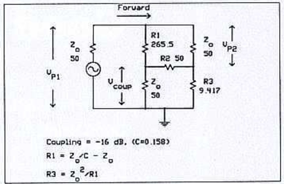
Above is Figure 3a from (Dunsmore 1991).

Exploration

The Dunsmore’s circuit has been rearranged to be similar to that used in my earlier articles.

Above is the rearranged schematic for discussion. It is similar to that used in the earlier article, but three components are renamed, R1, R2 and R3.

To analyse the circuit, we can use the mesh currents method. Mesh currents i1, i2 and i3 are annotated on the schematic.

The mesh equations are easy to write:

\(V_s=(zs+r1+r3) \cdot i1-r1 \cdot i2-r3 \cdot i3\\0=-r1 \cdot i1+(r1+r2+zd) \cdot i2-zd \cdot i3\\0=-r3 \cdot i1-zd \cdot i2+(r3+zd+zu) \cdot i3\\\)

This is a system of 3 linear simultaneous equations in three unknowns. In matrix notation:

\(\begin{vmatrix}i1\\i2\\i3 \end{vmatrix}=\begin{vmatrix}zs+r1+r3 & -r1 & -r3\\-r1 & r1+r2+zd & -zd\\-r3 & -zd & r3+zd+zu\end{vmatrix}^{-1} \times\begin{vmatrix}V_s\\0\\0\end{vmatrix}\\\)

Lets solve it in Python (since we are going to solve for some different input values) for Vs=1V.

First pass: zs, zref, zd are 50Ξ©, and zu is short circuit (1e-300 to avoid division by zero) for calibration and 25Ξ© for measurement.Β This example uses Dunmore’s 16dB coupling factor to derive the values for r1 and r3.

from scipy.optimize import minimize
import numpy as np
import cmath
import math

zs=50
zref=50
zd=50
c=0.5
c=10**(-16/20)
r3=zref/c-zref
r1=50
r2=zref**2/r3

print(c,r1,r2,r3)

#equations of mesh currents
#vs=(zs+r1+r3)β‹…i1βˆ’r1β‹…i2βˆ’r3β‹…i3
#0=βˆ’r1β‹…i1+(r1+r2+zd)β‹…i2βˆ’zdβ‹…i3
#0=βˆ’r3β‹…i1βˆ’zdβ‹…i2+(r3+zd+zu)β‹…i3

#s/c cal
zu=1e-300
#solve mesh equations
A=[[zs+r1+r3,-r1,-r3],[-r1,r1+r2+zd,-zd],[-r3,-zd,r3+zd+zu]]
b=[1,0,0]
#print(A)
#print(b)
res=np.linalg.inv(A).dot(b)
#print(res)
vcal=(res[1]-res[2])*zd
#print(vcal)

#check oc
zu=1e300
#solve mesh equations
A=[[zs+r1+r3,-r1,-r3],[-r1,r1+r2+zd,-zd],[-r3,-zd,r3+zd+zu]]
b=[1,0,0]
#print(A)
#print(b)
res=np.linalg.inv(A).dot(b)
#print(res)
vm=(res[1]-res[2])*zd
#print(vm)
rl=-20*math.log10(abs(vm)/abs(vcal))
print('ReturnLoss (dB) {:0.2f}'.format(rl))

#check 25
zu=25
#solve mesh equations
A=[[zs+r1+r3,-r1,-r3],[-r1,r1+r2+zd,-zd],[-r3,-zd,r3+zd+zu]]
b=[1,0,0]
#print(A)
#print(b)
res=np.linalg.inv(A).dot(b)
print(res)
vm=(res[1]-res[2])*zd
#print(vm)
rl=-20*math.log10(abs(vm)/abs(vcal))
print('ReturnLoss (dB) {:0.2f}'.format(rl))

This gives calculated rl=9.54dB which is correct. Also ReturnLoss for OC reconciles with the SC calibration.

This result is sensitive to the value of Zs and Zd, changing them alters the result. It may be that there are other combinations of Zs, Zd, r1, r2, r3 that give correct results in all cases.

A common manifestation of design failure is that ReturnLoss of a short circuit termination will be significantly different to an open circuit termination, and the difference may be frequency dependent when combined with imperfections in the bridge.

Conclusions

Dunsmore gives an alternative design, though his formulas still depended on Zs=Zd=r1=Zref.

References

Dunsmore, J. Nov 1991. Simple SMT bridge circuit mimics ultra broadband coupler In RF Design, November 1991: 105-108.

Last update: 17th September, 2024, 7:08 PM
Before yesterdayMain stream

A new clock plus 10MHz reference GPSDO

By: M0RVB
11 September 2024 at 16:14

I built a thing! This is a GPSDO using a PCB and kit of parts supplied by G8CUL and a OXCO from G1OGY. It uses a Jupiter GPS module which provides the PPS signal and a 10kHz output and the completed module provides 2x 10MHz and 1x 1MHz outputs. Although there are a number of such designs this one is nice in that it also has a display and shows the current date and time as UTC.

A GPSDO system based on a GPS module and OXCO module.

This was, I think my third SMD construction and certainly the Mose SMD devices including multi-legged chips. No issues in construction especially given the quality of the PCB that G8CUL had made.

The display on the GPSDO module showing the number of satellites and quality of signal.
The display on the GPSDO module showing the current date and UTC.

The backup battery is a CR2 3.3V type and helps with warm starting. As the regulator gets hot I managed to fit a heatsink between it and the rear of the case and hopefully this will sort out heat transfer, otherwise I may need to bolt another heatsink on the rear. Construction in a die cast box would have been better maybe but the blue/white box fits in with others in the shack, plus I had it already! The bezel is cut down from a 3D printed one from Printables.com designed specifically for the 2Γ—16 LCD displays. The button – which is not the best but I had one etc. – selects the various displays which include date and time, satellites seen, latitude, longitude, altitude and QRA locator.

Latest tooling addition

By: M0RVB
8 September 2024 at 08:55

I had a number of Molex pins to wire up recently. To make things easier I decided to use some 4-core signal cable I had but found that the insulation is so poor at resisting heat that soldering the Molex pins was a non-starter as it always ended up with bare wires. Of course, Molex pins are designed to be crimped… so off to eBay.

The latest addition to my toolbox arrived in a couple of days and made the job a lot easier.

A ratchet crimping tool suitable for a variety of connectors including Molex pins.

Fox flasher MkII update 9/2024

By: Owen
5 September 2024 at 22:21

Fox Flasher MkII and several follow on articles described an animal deterrent based on a Chinese 8051 architecture microcontroller, the STC15F104E.

Fox flasher MkII update 7/2019 documented a rebuild of the enclosure etc.

This is an update after five more years operation outside.

Above is a pic of the device. The polycarbonate case has yellowed a little. Importantly the cheap PVA has not crazed, it is kept dry by the outer enclosure, and a hydrophobic vent helps keeps the interior dry.

The battery is a pouch LiPo single cell, it is in good condition. A previous trial with 18650 LiIon cells showed they were unsuitable for the environmentals.

Last update: 6th September, 2024, 8:21 AM

The September – October SARC Communicator

1 September 2024 at 03:33
We're back!With another big issue to start the fall season. The September-October 2024 Communicator, digital periodical of Surrey Amateur Radio Communications is now available forΒ viewing or download. Some great projects and articles in this issue...

πŸ’Ύ

Vacuum Tubes – Electronics at Work: 1943 Educational Film

18 August 2024 at 18:32
In the classic educational film titled β€œElectronics at Work,” produced by Westinghouse in 1943, viewers are introduced to the fascinating world of vacuum tubes. This film highlights the crucial role these devices played in both military and commercial sectors, including radio telecommunications, radar, and various industrial applications. The narrative suggests that vacuum tubes provided the […]

…And Now The Little Ham Radio Workshop Is Starting To Become An Electronics/RF Lab…

By: KM1NDY
27 August 2024 at 03:00

From Top to Bottom:

  • Bell System CK-14510-L11 Analog Multimeter
  • Topward 8112 2MHz Digital Function Generator
  • Philips/Fluke PM-6666 120 MHz Frequency Counter
  • Tektronix CMC251 1.3GHz Frequency Counter
  • Tektronix 2465 300MHz 4-Channel Oscilloscope
  • Hameg HM5014 1GHz Spectrum Analyzer with Tracking Generator

Not shown are my RigExpert VNAs, the NanoVNA, the Koolertron 60MHz function generator, the Tacklife 30V 5A variable DC power supply, and handheld digital multi- and LCR meters. On the bench is the Weller WE1010NA soldering station. Oh yeah, and my Elegoo 3D printer.

I think its turning into a proper little radio lab! State of the art, circa 1982!

KM1NDY

"Matter Waves" -- A 1961 Bell Labs Film

25 August 2024 at 14:08

I continue to mine the AT&T video archive.Β  Here's a really wonderful 1961 film showing how particles really are waves also.Β  Β The simplicity of the gear that the Bell Labs folks used to demonstrate this is really admirable.Β  I would love to see the preceding film (the one that shows how light waves are really also particles).Β 

Vacuum Tubes – Electronics at Work: 1943 Educational Film

18 August 2024 at 18:32
In the classic educational film titled β€œElectronics at Work,” produced by Westinghouse in 1943, viewers are introduced to the fascinating world of vacuum tubes. This film highlights the crucial role these devices played in both military and commercial sectors, including radio telecommunications, radar, and various industrial applications. The narrative suggests that vacuum tubes provided the […]

Why did I give up the valve collection?

By: M0RVB
15 August 2024 at 16:31

Some of you may remember that I used to collect valves. I started collecting when I was around 6 years old, although back then it was more to impress friends than collect. An old directly heated valve plus a Lego battery box lit my desk up at primary school. I did not start collecting in earnest until the 1990’s and launched my first online valve museum in 1999. Since then the collection grew in several directions at once, including German WW2 types, Russian Cold War types and British military and civilian types. There were specials from all over the world as well including a few Japanese WW2 ones. Valves ranged from tiny little things to a RD150YB that had to live in the garage, and a 6-anode mercury arc rectifier that was equally not allowed in the house, and for good reason too. The main collection grew to over 3,000 types, many of which had duplicates, so probably 4,000 in total. And then there were boxes of valves that did not warrant adding to the collection.

And so the collection continued to expand. While on holiday in the US friend in the US was discussing collecting trends with me and another collecting friend and said he collected US antique types, others collected microwave types and, pointing at me he said I collected everything and there is nothing wrong in that. But it made me think what exactly is my interest. And so I decided to concentrate on what I found most interesting – British military types, mainly in the CV, and A, N and V military series. The collection included a number of CRTs as well and eventually took over the whole garage.

I decided then to concentrate solely on CV types and trimmed the collection to 1,500 types, again with duplicates taking the collection to over 2,000 valves. Of the remainder many were sold and many hundreds went to the National Valve Museum which was nearly as old as my own.

Eventually though three things happened. First, it was becoming increasingly difficult to find new additions. Second, the website was now seeing fewer and fewer actual hits (as opposed to search engine spiders), and, most importantly I realised it had become an obsession. Time to quit. I also came to the realisation that I had an awful lot of valves in lots of boxes and I never even looked at any once they went into a box.

So I decided to close the website and sell off anything I could, donating the remainder to the National Valve Museum. The website was essentially converted to flat HTML files with none of the database behind them and taken over by a member of the BVWS. Of course, all praise to them for doing that, but none to me for all my years of work. Par for the course. In the past 20 years I received just a handful comments thanking me for providing the photographs and information about the collection. I was somewhat surprises at the screams when I announced the website was to close. Of course, I did not make the website for that, I did it because I thought people might actually be interested, and they clearly were back at the turn of the millennium but times change.

I was fortunate that someone local took many of the CRTs and a bunch of valves as well. Of the rest, a few hundred are destined for friends in Australia, the Netherlands, Belgium and Italy but the logistics are going to be a nightmare. Several hundred have found new homes here in the UK. Of the thousands left these went to the National Valve Museum with the more mundane radio and TV types being scrapped as no-one wanted to come and get them. I am keeping many of the early magnetrons for later sale, and some of the more decorative valves for, well, decoration!

There are still several boxes and a cupboard full of valves and they are destined to be scrapped. Selling on eBay as an individual has become more and more complex over the years so I will rarely sell there. As no-one was interested in paying me a visit to take them away they will end up in the dump.

At its height the collection took over half the workshop and half the garage. Once trimmed down to the CV types it was still half the workshop. Now it is all under one bench and I have more space to set up the various tools that have been sidelined for years and actually get back to working on the house.

❌
❌