Engineers Embrace Repair Culture as New Law Takes Shape in California
12 May 2024 at 16:47
Last fall, California passed SB 244, otherwise known as the Right to Repair law, which...

Yaesu SP-8 Speaker Replacement. A good sounding, easy to find replacement - the Visaton R10S 4 inch 8 Ohm speaker. Also fits the FPS-101 and SP-101.
The post Yaesu SP-8 Speaker Replacement first appeared on N0UN.net. |
| Fig 1: The Hammond 1590 aluminum case housing the FE-5860A rubidium osc- oscillator and other circuitry - the markings faded by time and heat. Click on the image for a larger version. |
The first of these - my Efratom LP-101 - fired up just fine, despite having seen several years of inactivity. After letting it warm up for a few hours I dialed it in against my HP Z3801 GPSDO and was able to get it to hold to better than 5E-11 without difficulty.
My other rubidium frequency reference - the FEI FE-5680A - was another matter: At first, it seemed to power up just fine: I was using my dual-trace oscilloscope, feeding the 'Z3801 into channel 1 and the '5680A into channel 2 and watching the waveforms "slide" past each other - and when they stop moving (or move very, very slow) then you know things are working properly: See Figure 2, below, for an example of this.
That did happen for the '5680A - but only for a moment: After a few 10s of seconds of the two waveforms being stationary with respect to each other, the waveform of the '5680A suddenly took off and the frequency started "searching" back and forth, reaching only as high as a few Hz below exactly 10 MHz and swinging well over 100 Hz below that.
My first thought was something along the lines of "Drat, the oven oscillator has drifted off frequency..."
 |
| Fig 2: Oscillogram showing the GPS reference (red) and the FE-5680A (yellow) 10 MHz signals atop each other. Timing how long it takes for the two waveforms "slide" past each other (e.g. drift one whole cycle) allows long-term frequency measurement and comparison. Click on the image for a larger version. |
As it turns out, that was exactly what had happened.
Note:
I've written a bit more about the aforementioned rubidium frequency references, and you can read about them in the links below:
Oscillator out of range
While it is the "physics package" (the tube with the rubidium magic inside) that determines the ultimate frequency (6834683612 Hz, to be precise) it is not the physics package that generates this frequency, but rather another oscillator (or oscillators) that produce energy at that 6.834682612 GHz frequency, inject it into the cavity with the rubidium lamp and detect a slight change in intensity when it crosses the atomic resonance.
In this unit, there is a crystal oscillator that does this, using digital voodoo to produce that magic 6.834682612 GHz signal to divine the hyperfine transition. This oscillator is "ovenized" - which is to say, the crystal and some of the critical components are under a piece of insulating foam, and attached to the crystal itself is a piece of ceramic semiconductor material - a PTC (positive temperature coefficient) thermistor - that acts as a heater: When power is applied, it produces heat - but when it gets to a certain temperature the resistance increases, reducing the current consumption and the thermal input and the temperature eventually stabilizes.
Because we have the rubidium cell itself to determine our "exact" frequency, this oven and crystal oscillator need only be "somewhat" stable intrinsically: It's enough simply to have it "not drift very much" with temperature as small amounts of frequency change can be compensated, so neither the crystal oven - or the crystal contained within - need to be "exact".
 |
| Fig 3: The FE-5680A itself, in the lid of the case of the 1590 box to provide heat- sinking. As you can see, I've had this unit open before! Click on the image for a larger version. |
The give-away was that as the unit warmed up, it did lock, but only briefly: After a brief moment, it suddenly unlocked as the crystal warmed up and drifted low in frequency, beyond the range of the electronic tuning.
Taking the unit apart I quickly spotted the crystal oscillator under the foam and powering it up again, I kept the foam in place and watched it lock - and then unlock again: Lifting the foam, I touched the hot crystal with my finger to draw heat away and the unit briefly re-locked. Monitoring with a test set, I adjusted the variable capacitor next to the crystal and quickly found the point of minimum capacitance (highest frequency) and after replacing the foam, the unit re-locked - and stayed in lock.
Bringing it up to frequency
This particular '5680A is probably about 25 years old - having been a pull from service (likely at a cell phone site) and eventually finding its way onto EvilBay as surplus electronics. Since I've owned it, it's also seen other service - having been used twice in in ground stations used for geostationary satellite service as a stable frequency reference, adding another 3-4 years to its "on" time.
As quartz crystals age, they inevitably change frequency: In general, they tend to drift upwards if they are overdriven and slowly shed material - but this practice is pretty rare these days, so they seem to tend to drift downwards in frequency with normal aging of the crystal and nano-scale changes in the lattice that continue after the quartz is grown and cut: Operating at elevated temperature - as in an oven - tends to accelerate this effect.
By adjusting the trimmer capacitor and noting the instantaneous frequency (e.g. adjusting it mechanically before the slower electronic tuning could take effect) I could see that I was right at the ragged edge of being able to net the crystal oscillator's tuning range with the variable capacitor at its extreme low end, so I needed to raise the natural frequency a bit more.
If you need to lower a crystal's frequency, you have several options:
 |
| Fig 4: The tip of the screwdriver pointing at the added 2.2uH surface-mount inductor: It's the black-ish component at sort of a diagonal angle, wired across the two crystal leads. Click on the image for a larger version. |
Since the electrical "opposite" of a capacitor is an inductor, the above can be reversed if you need to raise the frequency of a crystal:
 |
| Fig 5: The crystal is under the round disk (the PTC heater) near the top of the picture and the adjustment capacitor is to the right of the crystal. Click on the image for a larger version. |
![]()
A moment of serendipity. Let’s face it, the internet can be a sewer. Yes, there’s quite a bit of useful information out there, but sometimes trying to find it is like sticking your hand in a toilet full of crap to fish out a hundred dollar bill. DATABASE Well, in... Read more »
The post Check Out This Really Cool Radio Manual Database. appeared first on Off Grid Ham.
No big troubleshooting here, the HP3312A function generator had been developing small fault over time, the last time I used it was not outputting signal or with the wrong shape, so decided to see what could be done.
This was the "sinusoidal" output:
Not good! Also the frequency was not in line with the bezel markings.
Here's the offending component on top board near the front panel.
The reference marked in the capacitor, if needed:
TRW 8508
HEW-331
.5MF +/- 10%
50 VDC
Better now after replacement, I didn't had 0.5MF as originally so by mistake placed a 2.2uF, got better but still some distortion seen:
I then replaced by a 1uF one and now it's perfect, in the future I will probably try to find the right value (0.5uF) and replace.
Have a nice day!
![]()
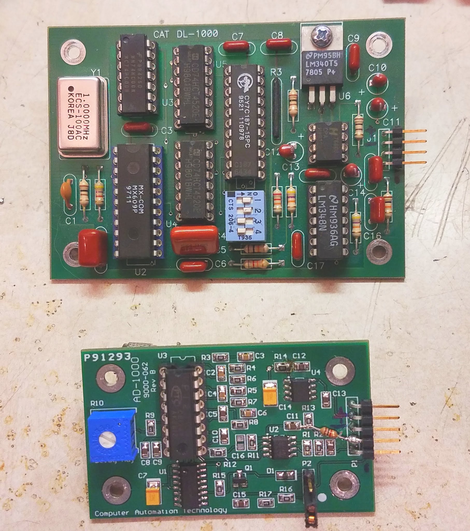 |
| Figure 1: The older DL-1000 (top) and the newer AD-1000, both after modification. Click on the image for a larger version. |
Comment:
There is a follow-up of this article where an inexpensive PT2399-based reverb board is analyzed and converted into a delay board suitable for repeater use: Using an inexpensive PT2399 music reverb/effects board as an audio delay - LINK
A few weeks ago I was helping one of the local ham clubs go through their repeaters, the main goal being to equalize audio levels between the input and output to make them as "transparent" as possible - pretty much a matter of adjusting the gain and deviation appropriately, using test equipment. Another task was to determine the causes of noises in the audio paths and other anomalies which were apparent to a degree at all of the sites.
All of the repeater sites in question use CAT-1000 repeater controllers equipped with audio delay boards to help suppress the "squelch noise" and to ameliorate the delay resulting from the slow response of a subaudible tone decoder. Between the sites, I ran across the older DL-1000 and the newer AD-1000 - but all of these boards had "strange" issues.
The DL-1000:
This board uses the MX609 CVSD codec chip which turns audio into a single-bit serial stream at 64 kbps using a 4-bit encoding algorithm, which is then fed into a CY7C187-15 64k x 1 bit RAM, the "old" audio data being read from the RAM and converted back to audio just before the "new" data is written.. To adjust the amount of delay in a binary-weighted fashion, a set of DIP switches are used to select how much of this RAM is used by enabling/disabling the higher-order address bits.
The problem:
It was noticed that the audio from the repeater had a bit of an odd background noise - almost a squeal, much like an amplifier stage that is on the verge of oscillation. For the most part, this odd audio property went unnoticed, but if an "A/B" comparison was done between the audio input and output - or if one inputted a full-quieting, unmodulated carrier and listened carefully on a radio to the output of the repeater, this strange distortion could be heard.
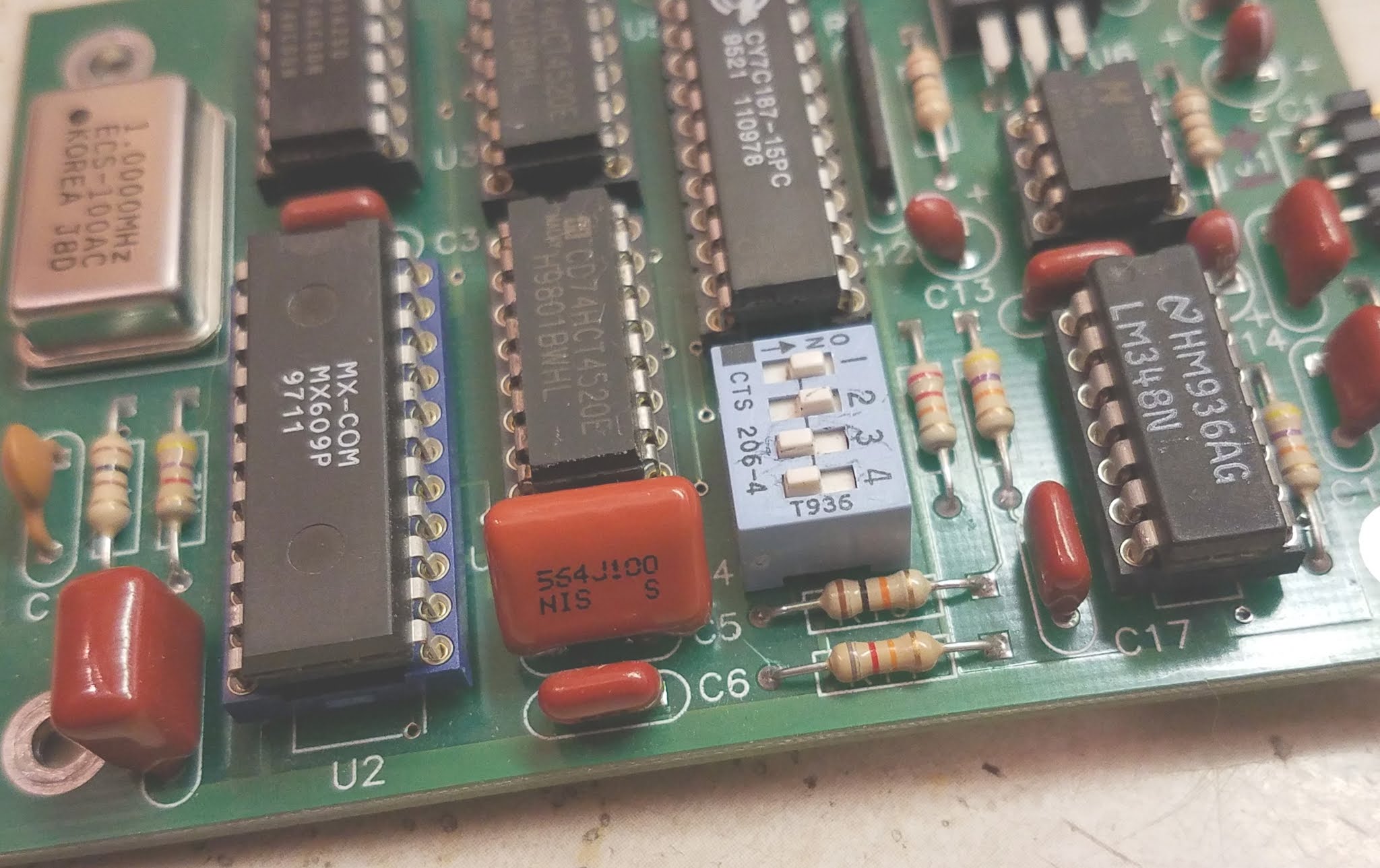 |
| Figure 2: The location of C5 on the DL-1000. A 0.56 uF capacitor was used to replace the original 0.1 (I had more of those than I had 0.47's) and either one would probably have been fome As noted below, I added another to the bottom of the board. Click on the image for a larger version. |
This issue was most apparent when a 1 kHz tone was modulated on a test carrier and strange mixing products could be heard in the form of a definite "warble" or "rumble" in the background, superimposed on the tone. Wielding an oscilloscope, it was apparent that there was a low-frequency "hitchhiker" on the sine wave coming out of the delay board that wasn't present on the input - probably the frequency of the low-level "squeal" mixing with the 1 kHz tone. Because of the late hour - and because we were standing in a cold building atop a mountain ridge - we didn't really have time to do a full diagnosis, so we simply pulled the board, bypassing the delay audio pins with a jumper.
On the workbench, using a signal tracer, I observed the strange "almost oscillation" on pin 10 of the MX609 - the audio input - but not on pin 7 of U7B, the op-amp driver. This implied that there was something amiss with the coupling capacitor - a 0.1uF plastic unit, C5, but because these capacitors almost never fail, particularly with low-level audio circuits, I suspected something fishy and checked the MX609's data sheet and noted that it said "The source impedance should be less than 100 ohms. Output channel noise levels will improve with an even lower impedance." What struck me was that with a coupling capacitor of just 0.1uF, this 100 ohm impedance recommendation would be violated at frequencies below 16 kHz - hardly adequate for voice frequencies!
 |
| Figure 3: The added 2.2uF tantalum capacitor on the bottom of the board across C5. The positive side goes toward the MX609, which is on the right. Click on the image for a larger version. |
Initially, I bridged C5 with another 0.1uF plastic unit and the audible squealing almost completely disappeared. I then bridged C5 it with a 0.47uF capacitor which squashed the squealing sound and moved the 100 ohm point to around 4 kHz, so I replaced C5 with a 0.56uF capacitor - mainly because I had more of those than small 0.47uF units.
Not entirely satisfied, I bridged C5 with a 10uF electrolytic capacitor, moving the 100 ohm impedance point down to around 160 Hz - a frequency that is below the nominal frequency response of the audio channel - and it caused a minor, but obvious quieting of the remaining noise, particularly at very low audio frequencies (e.g. the "hiss" sounded distinctly "smoother".) Because I had plenty of them on-hand, I settled on a 2.2 uF tantalum capacitor (100 ohms at 723 Hz) - the positive side toward U2 and tacked to the bottom of side of the board - which gave a result audibly indistinguishable from 10 uF. In this location, a good-quality electrolytic of 6.3 volts or higher would probably work as well, but for small-signal applications like this a tantalum is an excellent choice, particularly in harsh temperature environments.
At this point I'll note that any added capacitance should NOT
be done with ceramic units. Typical ceramic capacitors in the 0.1uF
range or higher are of the "Z5U" type
or similar and their capacitance changes wildly with temperature meaning that
extremes may cause the added capacitance to effectively "go away" and
the squealing noise may return under those conditions. Incidentally, these types of ceramic capacitors can also be microphonic, but unless you have strapped your repeater controller to an engine, that's probably not important.
Were I to do this to another board I would simply tack a small tantalum (or electrolytic) capacitor - anything from 1 to 10 uF, rated for 6 volts or more - on the bottom side of the board, across the still-installed, original C5 (as depicted in Figure 3) with the positive side of the capacitor toward U2, the MX609.
Note:
One of the repeater sites also had a "DL-1000A" delay board - apparently a later revision of the DL-1000. A very slight amount of the "almost oscillation" was noted on the audio output of this delay board, too, but between its low level and having limited time on site, we didn't investigate further.
This board appears to be similar to the DL-1000 in that it has many of the same chips - including the CY7187 RAM, but it doesn't have a socketed MX609 on the top of the board, and likely a surface-mount codec on the bottom. It is unknown if this is a revision of the original DL-1000 or closer to the DL-1000C which has a TP4057 - a codec functionally similar to the MX609.
The question arises as to why this modification might be necessary? Clearly, the designers of this board didn't pay close enough attention to the data sheet of the MX609 codec otherwise they would have probably fitted C5 with a larger value - 0.47 or 1 uF would have probably been "good enough". I suspect that there are enough variations of the MX609 - and that the level of this instability - is low enough that it would largely go unnoticed by most, but to my critical ears it was quite apparent when an A/B comparison was done when the repeater was passing a full-quieting, unmodulated carrier and made very apparent when a 1 kHz tone was applied.
* * * * * * * * * * * * * * *
The AD-1000:
This is a newer variant of the delay board that includes audio gating and it uses a PT2399, a chip commonly used for audio echo/delay effects in guitars pedals and other musical instrument accessories as it has an integrated audio delay chip that includes 44 kbits of internal RAM.
The problems:
This delay board had two problems: An obvious audio "squeal", very similar to that on the older DL-1000, but extremely audible, but there was a less obvious problem - something that sounded like "wow" and flutter of an old record on a broken turntable in that the pitch of the audio through the repeater would warble randomly. This problem wasn't immediately obvious on speech, but this pitch variation pretty much corrupted any DTMF signalling that one attempted to pass through the system, making the remote control of links and other repeater functions difficult.
RF Susceptibility:
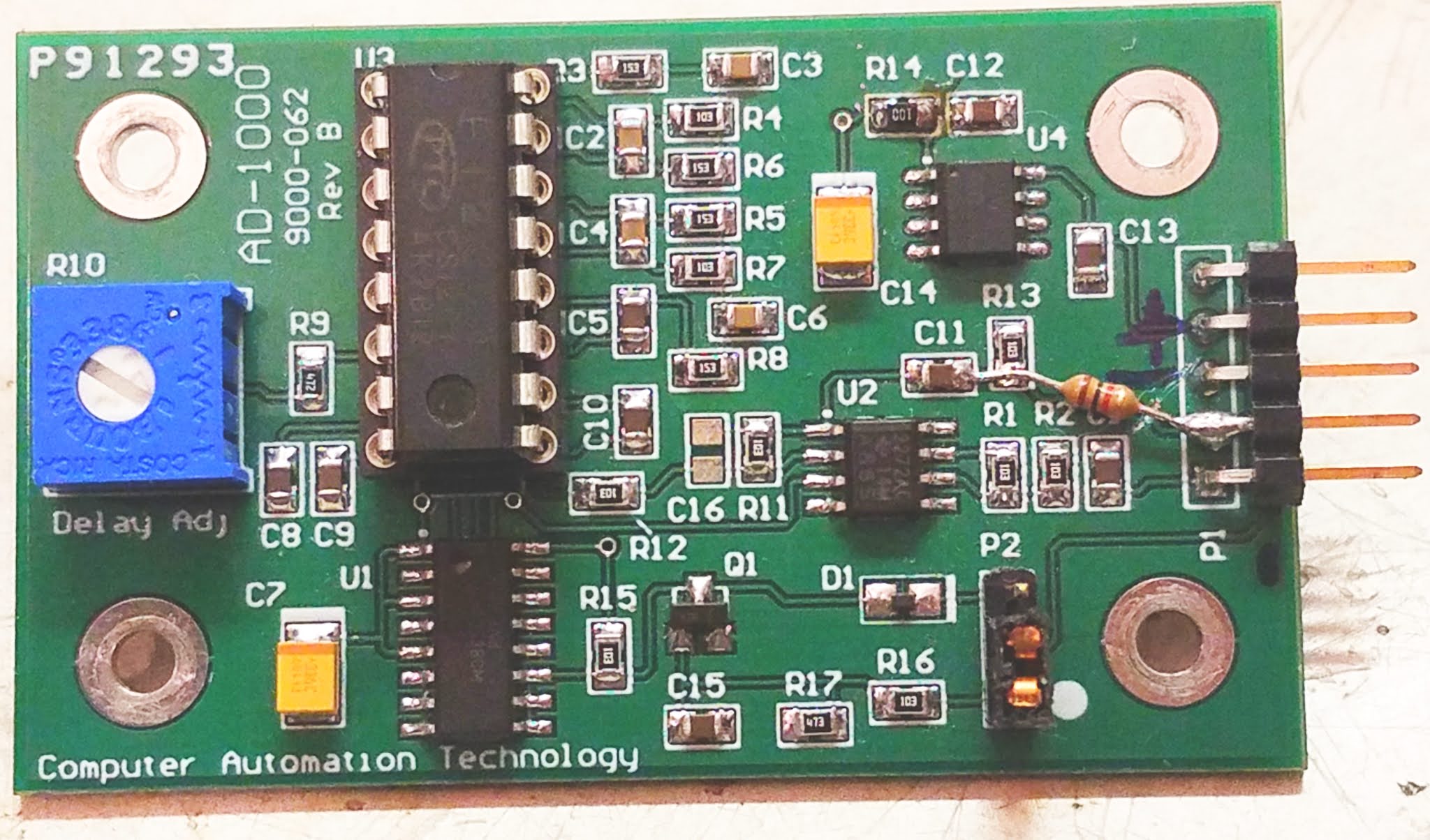 |
| Figure 4: The top of the modified AD-1000 board where the added 1k resistor is shown between C11/R13 and pin 2 of the connector, the board trace being severed. Near the upper-right is R14, replaced with a 10 ohm resistor, but simply jumpering this resistor with a blob of solder would likely have been fine. Click on the image for a larger version. |
Tracing the audio input, it passes through C1, a decoupling capacitor, and then R2, a 10k resistor - and this type of series resistance generally provides pretty good resistance to RF ingress, mainly because a 10k resistor like this has several k-ohms of impedance - even at VHF frequencies, which is far higher impedance than any piece of ferrite material could provide!
The audio output was another story: R13, another 10k resistor, is across the output to discharge any DC that might be there, but the audio then goes through C11, directly to pin 1 of U2, the output of an op-amp. While this may be common practice under "normal" textbook circumstances, sending the audio out from an op-amp into a "hostile" environment must be done with care: The coupling capacitor will simply pass any stray RF - such as that from a transmitter - into the op amp's circuitry, where it can cause havoc by interfering/biasing various junctions and upsetting circuit balance. Additionally, having just a capacitor on the output of an op amp can be a hazard if there also happens to be an external RF decoupling capacitor - or simply a lot of stray capacitance (such as a long audio cable) as this can lead to amplifier instability - all issues that anyone who has ever designed with an op amp should know!
 |
| Figure 5: The added 1000pF cap on the audio gating lead. A surface-mount capacitor is shown, soldered to the ground plane on the bottom of the board, but a small disk- ceramic of between 470 and 1000 pF would likely be fine. Click on the image for a larger version. |
Although not expected to be a problem, a 1000pF chip cap was also installed between the COS (audio gate) pin (pin 5) and ground - just in case RF was propagating into the audio path via this control line - this modification being depicted in Figure 5.
Of course, it will take another site visit to reinstall the board to determine if it is still being affected by the RF field and take any further action.
And no, the irony of a repeater's audio circuitry being adversely affected by RF is not lost on me!
The "wow" issue:
On the bench I recreated the "wow" problem by feeding a tone into the board, causing the pitch to "bend" briefly as the level was changed, indicating that the clock oscillator for the delay was unstable as the sample frequency was changing between the time the audio entered and exited the RAM in the delay chip. Consulting the data sheet for the PT2399 I noted that its operating voltage was nominally 5 volts, with a minimum of 4.5 volts - but the chip was being supplied with about 3.4 volts - and this changed slightly as the audio level changed. Doing a bit of reverse-engineering, I noted that U4, a 78L05, provided 5 volts to the unit, but the power for U2, the op amp and U3, the PT2399, was supplied via R14 - a 100 ohm series resistor: With a nominal current consumption of the PT2399 alone being around 15 milliamps, this explained the 1.6 volt drop.
The output at resistor R14 is bypassed with C14, a 33 uF tantalum capacitor, likely to provide a "clean" 5 volt supply to decouple U14's supply from the rest of the circuit - but 100 ohms is clearly too much for 15 mA of current! While testing, I bridged (shorted) R14 and the audio frequency shifting stopped with no obvious increase in background noise, so simply removing and shorting across R14 is likely to be an effective field repair, but because I had some on hand, I replaced R14 with a 10 ohm resistor as depicted in Figure 4 and the resulting voltage drop is only a bit more than 100 millivolts, but retaining a modicum of power supply decoupling and maintaining stability of the delay line.
 |
| Figure 6: Schematic of the AD-1000, drawn by inspection and with the aid of the PT2399 data sheet. Click on the image for a larger version. |
Figure 6, above, is a schematic drawn by inspection of an AD-1000 board with parts values supplied by the manual for the AD-1000. As for a circuit description, the implementation of the PT2399 delay chip is straight from the data sheet, adding a dual op-amp (U2) for both input and output audio buffering and U1, a 4053 MUX, along with Q1 and components, were added to implement an audio gate triggered by the COS line.
As can be seen, all active circuits - the op-amp, the mux chip and delay line - are powered via R14 and suffer the aforementioned voltage drop, explaining why the the supply voltage to U3 varied with audio content, causing instability in audio frequencies and difficulty in decoding DTMF tones passed through this board - and why, if you have one of these boards, you should make the recommended change to R14!
Conclusion:
What
about the "wow" issue? I'm really surprised that the value of R14 was
chosen so badly. Giving the designers the benefit of the doubt, I'll
ignore the
possibility of inattention and chalk this mistake, instead, to
accidentally using a 100 ohm resistor instead of a 10 ohms resistor -
something that might have happened at the board assembly house rather
than being part of the original design.
After a bit of digging around online I found the manual for the AD-1000 (found here) which includes a parts list (but not a schematic) that shows a value of 100 ohms for R14, so no, the original designers got it wrong from the beginning!
While the RF susceptibility issue will have to wait until another trip to the site to determine if more mitigation (e.g. addition of ferrite beads on the leads, additional bypass capacitance, etc.) is required, the other major problems - the audio instability on the DL-1000 and the "wow" issue on the AD-1000 have been solved.
* * * * * * * * * * * * * * *
Comments about delay boards in general:
A signal/noise ratio of around 45 dB is on par with a "full quieting" signal on a typical narrowband FM communications radio link so the lower S/N ratio of the MX609 as compared with the PT2399 would likely go unnoticed. Were I to implement a repeater system with these delay boards I would preferentially locate the MX609-based delay boards in locations where the noise contribution would be minimized (e.g. the input of the local repeater) while placing the quieter PT2399-based board in signal paths - such as a linked system - where one might end up with multiple, cascaded delay lines on link radios as the audio propagates through the system. Practically speaking, it's likely that only the person with a combination of a critical ear and OCD is likely to even notice the difference!
This page stolen from ka7oei.blogspot.com
[End]
![]()

I've done a previous repair on this device because I got it without being working on the 18Ghz range. I suspect this will not be the last one given it's age.
Anyhow, one of this days I turned it on to check the output frequency of a FVC99 module and it was displaying all entrance selector LED's on (should be one at a time) and no change on the input by pressing the band selector. Also there was no activity on the display for the source locking.
I suspect the usual bad contacts (it's slot based construction) or power supply, more to the power supply side since the equipment hadn't been moved (it's a bit sensitive on moving/vibrations and that had been the cause of the first repair).


I can measure again but I'm preparing a home made counter in case this one fails again in the future.
Have a nice day!
![]()
Following the first repair of the Wavetek 3001, I knew that there was another issue with the 400Hz modulation oscillator, it was doing some "FM" oscillations so in practice I could only use the 1Khz tone.

Troubleshooting and comparing with the 1Khz oscillator, it was visible the waveform at C6/CR2 junction oscillating/FM'ing a little. Interesting enough by probing with the scope at the drain of Q2 it disappeared. I tried first to swap C6 to no effect, then swapped CR2 and it stopped but trying with the diode in and inverted polarization it would continue the same so it was either wrong assembled at the factory or it's for the moment just masking any other situation, probably Q2.
Before the previous testing I replace IC2 with IC1 (for the 1Khz) to no good effect so decided the issues was not the opamp.

I left like that, with the diode replaced (used a 1n4148 for the
moment, didn't even checked the exact spec in the manual)
After demodulation on an envelop detector it's now fine:


Since it's a bit of a pain to take and access the modulator/modulation board I opted to solder the diode from the pcb track side and leave it for the moment, also left the original diode in place with one leg open:

Since some times the unleveled light still comes on I suspect further recapping at the internal modules might be needed in the future.
Have a great day!
![]()