This event happens seasonally, on the 3rd full weekend of the month (Saturday & Sunday UTC). These are ‘activity weekends’ where the main purpose is to get out in the parks, and have as much fun as possible.
Winter – 3rd Full Weekend of January. January 18-19, 2025
Spring – 3rd Full Weekend of April. April 19-20, 2025
Summer – 3rd Full Weekend of July. July 19-20, 2025
Autumn – 3rd Full Weekend of October. October 19-20, 2024
Hope to get you in my Logs during the upcoming event….
Remember yesterday when I mentioned the latest addition to my POTA setup, the Xiegu 5105 QRP rig….
Well this morning I decided to test it out and see how much work I would have to do with setting the parameters such as mic gain, processor, to make it sound like me… I was also testing out my EARCHI 9:1 unun with a 29.5 foot random wire to see how it would play with the built in AT of the 5105.
I figured I might as well do the testing at a POTA location just in case I was able to turn the test into an activation.
For this I chose Fort Frontenac POTA CA-5303. Its fairly easy to get there via the Kingston Transit system and its also close to downtown and all the amenities I might need. In the North East corner of the picture you will notice some white lines on the ground.
They are actually the walls of what’s left of that part of the Fort. Also the only parts of the Historic Site that is open to the public.
I leaned my MFJ 33 foot mast (supporting the 9:1 and wire in the vertical configuration) up against the tree.
And then ran the COAX over to the remains of the wall and set up my radio there and started operating.
My first contact was on 7.255 with the NCS of the ECARS net. He did hear me and considering I was QRP I was pleased. He did tell me that my audio seemed hot as if I was overdriving things. Lowering my voice seemed to help.
After that I looked at POTA Spots and managed to get W2IDG and VE3FI into the log from their parks and then finished up with the NCS of the MidCars net on 7.258.. All contacts were made on 40m SSB. I tried 20 SSB and was hearing lots of stations including a POTA Activation in VO1 but no luck breaking any of the pileups.
Then I figured it was time to get home and try to re configure the radio to my liking… I turned off the Speech Processor and lowered the Mic Gain from 60 to 40. Over the next few days I will get out again and see what else I have to do to get things sounding right.
The concept behind DME is simple: the aircraft broadcasts a signal pulse, and a ground station receives and repeats the pulse back at another frequency. The aircraft receives the return pulse, and from the time it has taken to receive that return pulse, the distance to the ground station can be determined. The frequencies used are between 960 MHz and 1215 MHz, and the aircraft and ground station pulses are always spaced apart by 63 MHz.
In his post, Daniel explains how he records the two signals spaced 63 MHz apart using his LimeSDR. Recording this large bandwidth has some challenges since typically the LimeSDR only supports a bandwidth of 61.44 MHz, which is too small for the 63 MHz spacing. However, Daniel explains in his post how he got around this limitation by using the two RX channels on the LimeSDR, sampling at a higher 80 MSPS sample rate, and then using the LimeSDR DSP to downconvert and decimate each DME channel to 2.5 MSPS, making the final sample rate small enough to be sent over USB.
The rest of the post details his experiments, analysis, and results when receiving the two DME channels through GNU Radio.
We’ve recently added a new room to the Matrix HAM Radio Space for Digital Voice modes as this was an area of interest that didn’t really fit into any of the other rooms.
The new Digital Voice room has attracted a lot of attention from members, with a lot of the focus being on the AllStarLink system. Michael, DK1MI built an AllStarLink node in the cloud for us all to use for Matrix Nets and so I decided I had to get in on the fun.
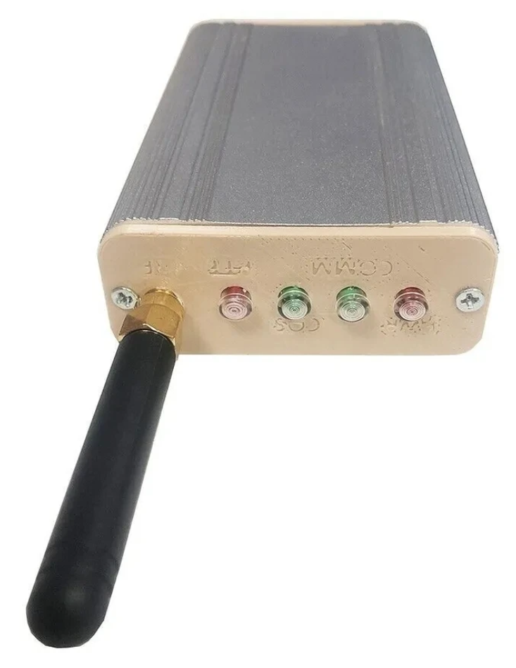
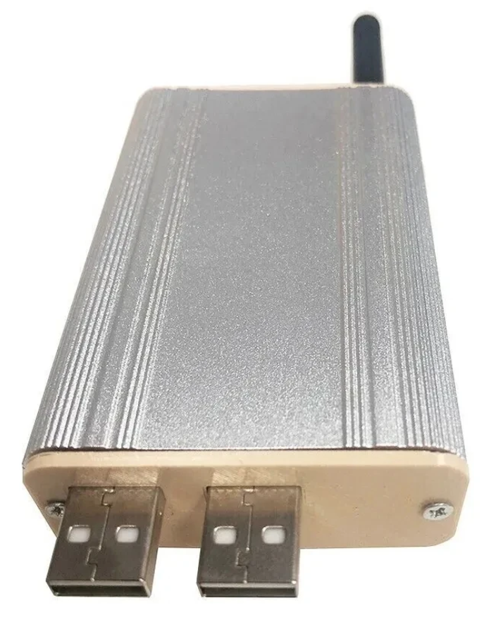
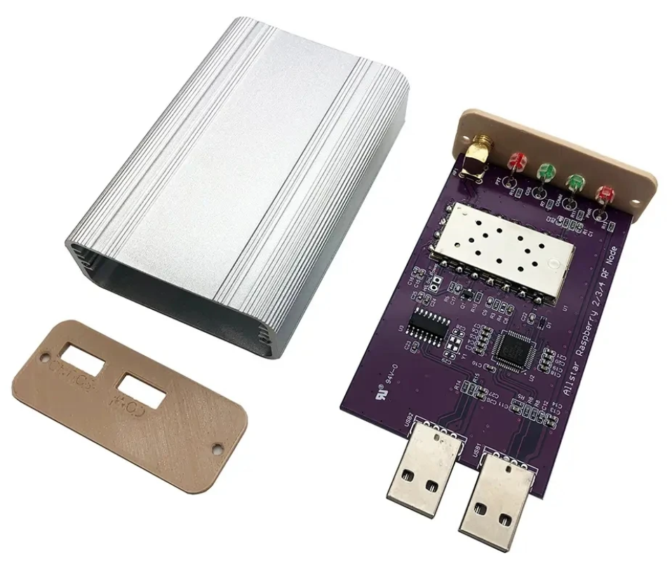
Jumbospot SHARI SA818 Amateur Radio AllStarLink Radio Interface Front Panel ViewJumbospot SHARI SA818 Amateur Radio AllStarLink Radio Interface Rear ViewJumbospot SHARI SA818 Amateur Radio AllStarLink Radio Interface stripped down View
The two USB connectors on the SHARI device are position such that they plug into two of the available 4 USB ports on the RaspberryPi without the need for cables. This keeps the whole solution together in one neat package.
Before you start you will need to obtain a node number and secret (password) from the AllStarLink Portal. To get this you will need to provide proof to the AllStarLink administrators that you are a licensed Amateur Radio (HAM) operator. This is done by uploading a copy of the first page of your HAM licence to the website for the admin team to check. This can take 24hrs to be completed so make sure you get this all done before trying to build your node. You cannot build a node successfully without a node number and secret.
Of course you will also need a transceiver that can operate on the 438.800Mhz frequency or other frequency of your choice on the 2m or 70cm HAM band.
You will also need to open port 4569 on your internet router and setup port forwarding to the IP Address that you will be using on your RaspberryPi node. It’s important to use a static IP Address on your RaspberryPi.
There are quite a few different Linux based operating system (O/S) images that are available for the RaspberryPi devices that have been specifically tailored for the AllStarLink node and include all the necessary software and library packages out the box.
Once downloaded you need to burn the ISO image onto a suitable SD card for your RaspberryPi. I use BalenaEtcher as it’s extremely quick and reliable at burning ISO images to SD cards.
Of course if you are a hardline Linux command line junkie you can always use dd to create the SD card.
Once you’ve got your O/S onto your SD card, slot it into your RaspberryPi making sure your SHARI device is connected to the two USB ports and then power it up. Make sure you have a good PSU for the RaspberryPi as the two devices together draw around 3A of current during the transmit cycle. (I use a 3.6A PSU from Amazon).
The default login for the Raspbian O/S is shown below. Login via SSH and configure your RaspberryPi for your local network. It’s important to use a static IP Address configured either directly on the RaspberryPi or via DHCP in your router.
Next you need to change directory into the asterisk config file directory using the command shown below:
cd /etc/asterisk
In this directory you will find all the default config files that come as part of the distro. For this build we’re not going to use them and so we need to move them out of the way ready for a set of config files that have already been configured correctly.
Using the following commands create a new directory, move into that new directory and then move all the unwanted configuration files into it:
mkdir ORIGINAL-CONF-FILES
cd ./ORIGINAL-CONF-FILES
mv ../*.conf ./
ls -la
cd ../
You should now be back in the /etc/asterisk directory which will now be empty apart from the custom directory which we left in place.
You now need to copy the correctly configured configuration files into the /etc/asterisk directory. Start by downloading the zip file containing the new configuration files
Once downloaded, copy the .zip file into the repeater users home directory (/home/repeater) using either scp on the Linux command line or if using Windows you can use the FileZilla Client in SFTP mode using the login details above.
Once you have the .zip file in the repeater user’s home directory you need to copy the file into the /etc/asterisk directory as user root:
Next as user root, change directory into the /etc/asterisk directory and unzip the .zip file:
cd /etc/asterisk
unzip ./AllStarLink-Config-v3.zip
Once the file is unzipped you will have a directory called AllStarLink-Config in the /etc/asterisk directory. You now need to cd into the directory, copy all the files out of it into the /etc/asterisk directory leaving a copy in the AllStarLink-Config directory for future reference:
cd /etc/asterisk/AllStarLink-Config
cp ./* /etc/asterisk
cd /etc/asterisk
You now need to move a couple of files into the repeater users home directory using the following commands:
The gpioBASH script and configuration details were supplied by Mark, G1INU in the Digital Voice room on the Matrix. It adds the COS light functionality to the setup. The COS light will now light every time the SA818 hears RF on the input.
The next thing you need to do is configure the SA818 radio device in the SHARI. The script I used was originally from https://wiki.fm-funknetz.de/doku.php?id=fm-funknetz:technik:shari-sa818 all I’ve done is change the entries to switch off CTCSS and change the frequency to 438.800Mhz. Configuring the SA818 is done by running the SA818-running.pyPython programme that you moved into the repeater user home directory. Making sure you are still user root, run the following commands:
cd /home/repeater
./SA818-running.py
At this point your SHARI SA818 device will be configured to operate on 438.800Mhz and CTCSS will be disabled.
If you want to change the frequency or enable and set a CTCSS tone to access the node you will need to edit the Python programme using your favourite text editor and change the entries accordingly. Once changed rerun the program as shown above and your SHARI will be reconfigured to your new settings.
Next you need to move the allmon.ini.php file into the correct directory so that it enables access to the Allstar Monitor web page on the device so that you can manage connecting/disconnecting nodes. Use the following commands as user root to achieve this:
The allmon.ini.php file needs to have your node name entered into it to work correctly. As user root, change directory and edit the file using your favourite editor.
cd /var/www/html/allmon2
Using your text editor, search for the line starting [XXXXX] and change the XXXXX to your node number. Save the change and exit the file.
At this point you are almost complete, all that is left to do is add your node number and node secret into the appropriate configuration files in the /etc/asterisk directory.
Since I am a Linux command line junkie I use vi to edit all the configuration files on the command line as user root, but you can use any editor of your choice.
cd /etc/asterisk
Start with the extensions.conf file. Search for the line starting with NODE = and delete the XXXXX entry and insert your node number. Save the file and exit it.
Next you need to edit the iax.conf file. This time search for the line starting with register= and change the XXXXX for your node number and the YYYYYYYYYYYY for your node secret. Be careful not to accidentally delete any other characters in the lines otherwise it will corrupt the configuration file.
In the same file search for the two lines that start with secret = and change the YYYYYYYYYYYY for your node secret. Once you have changed both of the secret entries, save and exit the file.
The final file to edit is the rpt.conf file. Once again open the file using your favourite editor and search for the line starting with XXXXX = radio@127.0.0.1:4569/XXXXX, change the XXXXX entries for your node number making sure not to delete any other characters next to the XXXXX entries.
Further down in the same file there is a line that starts with [XXXXX], once again change the XXXXX for your node number making sure to keep the square brackets at each end of the node number as you edit it.
Finally move down to the very bottom of the file and find the two lines that start with /home/repeater/gpio, once again change the XXXXX entries for your node number.
The final thing to change in the rpt.conf file is to replace my callsign with your own callsign so that the node identifies itself correctly. Scroll through the file until you find the two lines shown below, delete M0AWS and add your own callsign instead making sure you keep all the spaces between words as shown below.
idrecording = |i DE M0AWS
idtalkover = |i DE M0AWS
Once this is done, save and exit the file. At this point your node should be fully configured and will only require a reboot to get it working.
As user root, reboot your raspi using the reboot command.
reboot
Once your raspi comes back online, login using SSH as user repeater and then become root user using the sudo command detailed above.
You now need to create the admin user password for the Allstar Monitor web page on the device. This is done using the following commands as user root:
cd /var/www/html/allmon2
htpasswd -c .htpasswd admin
You will be asked to enter a password twice for the admin user. Make sure you make a note of this user/password as you will need it to login to the web page.
Finally check that the controlpanel.ini.php file is in the /var/www/html/allmon2 directory:
ls -la /var/www/html/allmon2/controlpanel.ini.php
If the file isn’t shown in the directory, enter the following commands to create the file in the correct place as user root and then exit the SSH session:
cd /var/www/html/allmon2
cp ./controlpanel.ini.txt ./controlpanel.ini.php
cd
exit
Once this is done your configuration is complete, logout from the terminal session by entering exit once more and your SSH session will terminate.
Using your favourite web browser enter the IP Address of your raspi into the URL bar as shown below:
http://<Your-Raspi-IP>/allmon2
Note: remove the <> from the URL once you have entered the required information.
Once this is done you should be presented with your node control panel as shown below.
First visit to the AllStar Monitor Web Page
Login using Admin and the password you set above and you are now ready to start using your node.
It’s a good idea to connect to node 55553 which is a parrot test node to check your audio levels. You can do this by entering the node into the field at the top left and pressing the connect button.
M0AWS AllStarLink Node 61928 connected to 55553 Parrot
Once connected, tune your radio to 438.800Mhz FM and transmit a test message using your callsign and test123, or something similar. The parrot will then play your recording back to you so that you can hear how you sound. It will also comment on your audio level as to whether it is OK or not.
You are now connected to AllStarLink network and have the world at your finger tips. Below is a small list of nodes in the UK, Australia and America to get you started chatting with other HAMs via your node.
57881	Matrix HAM Radio Space AllStarLink Node (Hosted by Dk1MI)
55553	ASL Parrot for testing
41522	M0HOY HUBNet Manchester, UK
60349	VK6CIA 439.275 Perth, Western Australia
51077	VK6SEG South West Hub B Albany WA
2167	M0JKT FreeSTAR UK HUB 2 freestar.network
53573	NWAG NW AllStar Group Lancashire, UK
27339	East Coast Hub Wilmington NC USA
M0AWS AllStarLink Node 61928 sitting on the equipment rack
Thanks to Michael, DK1MI for building and hosting the Matrix HAM Radio Space AllStarLink Node (57881) and getting us all started in the world of AllStarLink!
We hope to be having regular Matrix Net’s on the node soon for all Matrix members and visitors. We’ll organise days/times via the Digital Voice room.
Following on from my article about my QO-100 Satellite Ground Station Complete Build, this article goes into some detail on the Node-RED section of the build and how I put together my QO-100 Satellite Ground Station Dashboard web app.
The Node-RED project has grown organically as I used the QO-100 satellite over time. Initially this started out as a simple project to synchronise the transmit and receive VFO’s so that the SDR receiver always tracked the IC-705 transmitter.
Over time I added more and more functionality until the QO-100 Ground Station Dashboard became the beast it is today.
M0AWS QO-100 Ground Station Control Dashboard built using Node-RED.
Looking at the dashboard web app it looks relatively simple in that it reflects a lot of the functionality that the two radio devices already have in their own rights however, bringing this together is actually more complicated than it first appears.
Starting at the beginning I use FLRig to connect to the IC-705. The connection can be via USB or LAN/Wifi, it makes no difference. Node-RED gains CAT control of the IC-705 via XMLRPC on port 12345 to FLRig.
To control the SDR receiver I use GQRX SDR software and connect to it using RIGCTL on GQRX port 7356 from Node-RED. These two methods of connectivity work well and enables full control of the two radios.
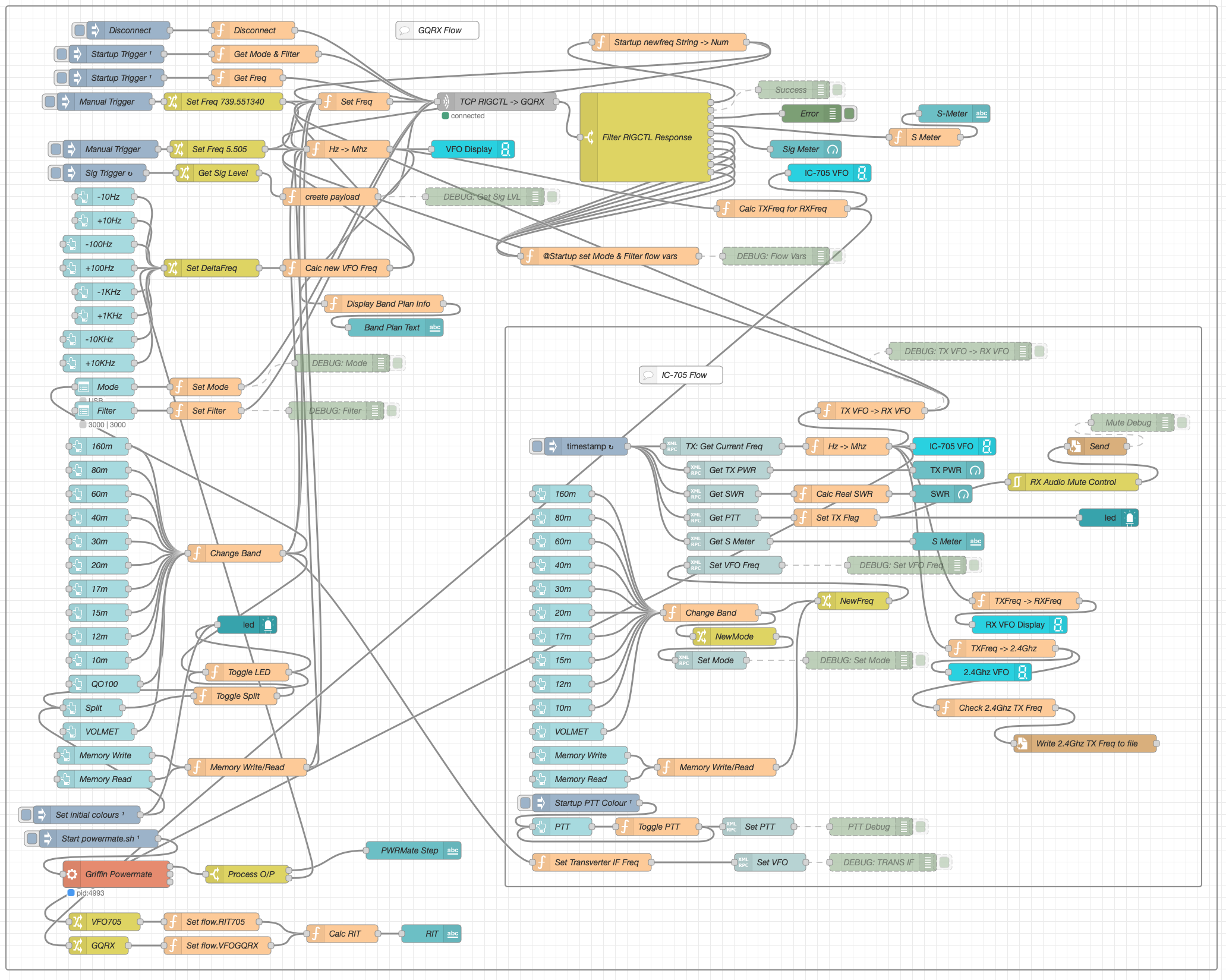
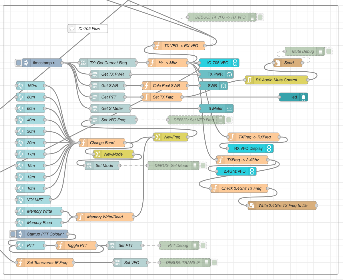
M0AWS Node-RED QO-100 Ground Station Dashboard Flow as of 12/06/24
The complete flow above looks rather daunting initially however, breaking it down into its constituent parts makes it much easier to understand.
There are two sections to the flow, the GQRX control which is the more complex of the two flows and the comparatively simple IC-705 section of the flow. These two flows could be broken down further into smaller flows and spread across multiple projects using inter-flow links however, I found it much easier from a debug point of view to have the entire flow in one Node-RED project.
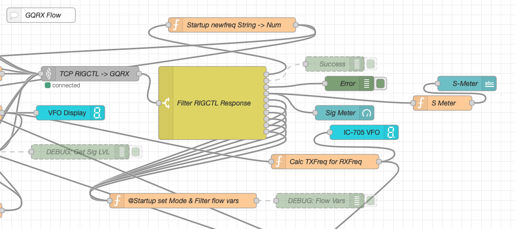
Breaking down the flow further the GQRX startup section (shown below) establishes communication with the GQRX SDR software via TCP/IP and gets the initial mode and filter settings from the SDR software. This information is then used to populate the dashboard web app.
M0AWS Node-RED QO-100 Ground Station Dashboard – GQRX Startup Flow
The startup triggers fire just once at initial startup of Node-RED so it’s important that the SDR device is plugged into the PC at boot time.
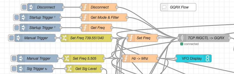
All the startup triggers feed information into the RIGCTL section of the GQRX flow. This section of the flow (shown below) passes all the commands onto the GQRX SDR software to control the SDR receiver.
M0AWS Node-RED QO-100 Ground Station Dashboard – GQRX RIGCTL Flow
The TCP RIGCTL -> GQRX node is a standard TCP Request node that is configured to talk to the GQRX software on the defined IP Address and Port as configured in the GQRX setup. The output from this node then goes into the Filter RIGCTL Response node that processes the corresponding reply from GQRX for each message sent to it. Errors are trapped in the green Debug node and can be used for debugging.
The receive S Meter is also driven from the the output of the Filter RIGCTL Response node and passed onto the S Meter function for formatting before being passed through to the actual gauge on the dashboard.
Continuing down the left hand side of the flow we move into the section where all the GQRX controls are defined.
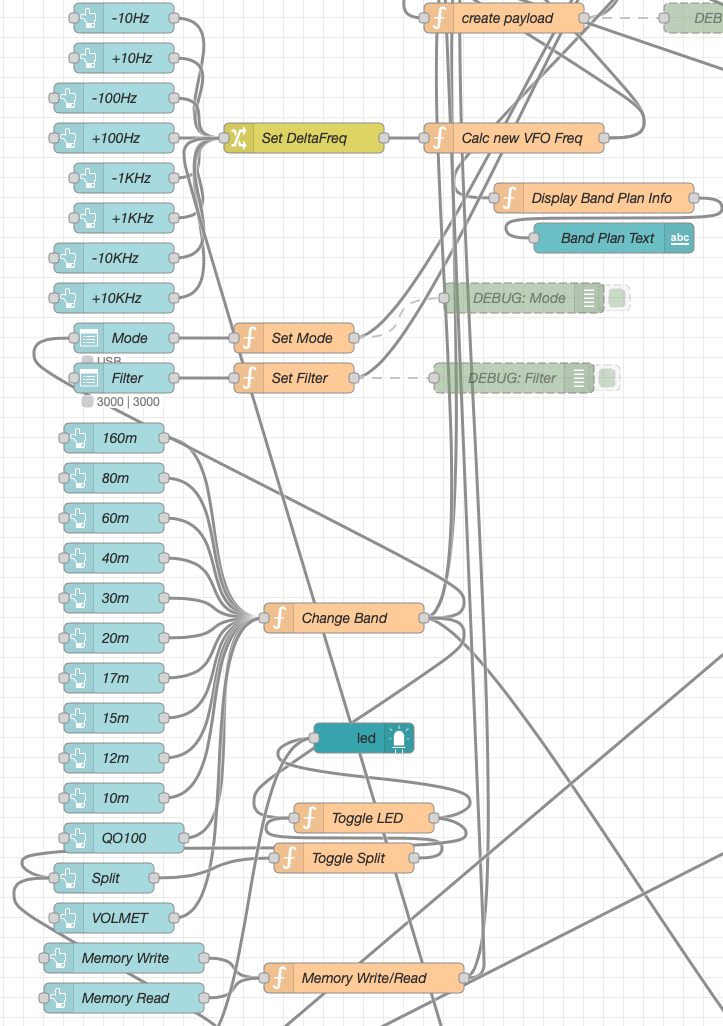
M0AWS Node-RED QO-100 Ground Station Dashboard – GQRX Controls Flow
In this section we have the VFO step buttons that move the VFO up/down in steps of 10Hz to 10Khz. Each button press generates a value that is passed onto the Set DeltaFreq change node and then on to the Calc new VFO Freq function. From here the new VFO frequency is stored and passed onto the communications channel to send the new VFO frequency to the GQRX software.
The Mode and Filter nodes are simple drop down menus with predefined values that are used to change the mode and receive filter width of the SDR receiver.
Below are the HAM band selector buttons, each of these will use a similar process as detailed above to change the VFO frequency to a preset value on each of the HAM HF Bands.
The QO-100 button puts the transmit and receive VFO’s into synchro-mode so that the receive VFO follows the transmit VFO. It also sets the correct frequency in the 739Mhz band for the downlink from the LNB in GQRX SDR software and sets the IC-705 to the correct frequency in the 2m VHF HAM band to drive the 2.4Ghz up-converter.
The Split button allows the receive VFO to be moved away from the transmit VFO for split operation when in QO-100 mode. This allows for the receive VFO to be moved away so that you can RIT into slightly off frequency stations or to work split when working DXpedition stations.
The bottom two Memory buttons allow you to store the current receive frequency into a memory for later recall.
At the top right of this section of the flow there is a Display Band Plan Info function, this displays the band plan information for the QO-100 satellite in a small display field on the Dashboard as you tune across the transponder. Currently it only displays information for the satellite, at some point in the future I will add the necessary code to display band plan information for the HF bands too.
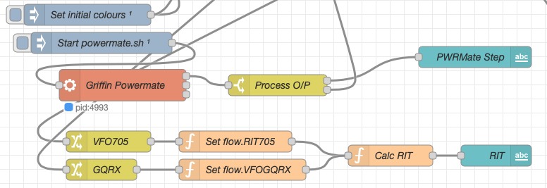
The final section of the GQRX flow (shown below) sets the initial button colours and starts the Powermate USB VFO knob flow. I’ve already written a detailed article on how this works here but, for completeness it is triggered a few seconds after startup (to allow the USB device to be found) and then starts the BASH script that is used to communicate with the USB device. The output of this is processed and passed back into the VFO control part of the flow so that the receive VFO can be manually altered when in split mode or in non-QO-100 mode.
M0AWS Node-RED QO-100 Ground Station Dashboard – Powermate VFO Flow
The bottom flows in the image above set some flow variables that are used throughout the flow and then calculates and sets the RIT value on the dashboard display.
The final section of the flow is the IC-705 control flow. This is a relatively simple flow that is used to both send and receive data to/from the IC-705, process it and pass it on to the other parts of the flow as required.
M0AWS Node-RED QO-100 Ground Station Dashboard – IC-705 Control Flow
The IC-705 flow is started via the timestamp trigger at the top left. This node is nothing more than a trigger that fires every 0.5 seconds so that the dashboard display is updated in near realtime. The flow is pretty self explanatory, in that it collects the current frequency, transmit power, SWR reading, PTT on/off status and S Meter reading each time it is triggered. This information is then processed and used to keep the dashboard display up to date and to provide VFO tracking information to the GQRX receive flow.
On the left are the buttons to change band on the IC-705 along with a button to tune to the VOLEMT on the 60m band. Once again there two memory buttons to save and recall the IC-705 VFO frequency.
The Startup PTT Colour trigger node sets the PTT button to green on startup. The PTT button changes to red during transmit and is controlled via the Toggle PTT function.
At the very bottom of the flow is the set transverter IF Freq function, this sets the IC-705 to a preselected frequency in the 2m HAM band when the dashboard is switched into QO-100 mode by pressing the QO-100 button.
On the right of the flow there is a standard file write node that writes the 2.4Ghz QO-100 uplink frequency each time it changes into a file that is used by my own logging software to add the uplink frequency into my log entries automatically. (Yes I wrote my own logging software!)
The RX Audio Mute Control filter node is used to reduce the receive volume during transmit when in QO-100 full duplex mode otherwise, the operator can get tongue tied hearing their own voice 250ms after they’ve spoken coming back from the satellite. This uses the pulse audio system found on the Linux platform. The audio is reduced to a level whereby it makes it much easier to talk but, you can still hear enough of your audio to ensure that you have a good, clean signal on the satellite.
As I said at the beginning of this article, this flow has grown organically over the last 12 months and has been a fun project to put together. I’ve had many people ask me how I have created the dashboard and whether they could do the same for their ground station. The simple answer is yes, you can use this flow with any kind of radio as long as it has the ability to be controlled via CAT/USB or TCP/IP using XMLRPC or RIGCTL.
To this end I include below an export of the complete flow that can be imported into your own Node-RED flow editor. You may need to make changes to it for it to work with your radio/SDR but, it shouldn’t take too much to complete. If like me you are using an IC-705 and any kind of SDR controlled by GQRX SDR software then it’s ready to go without any changes at all.
Over on YouTube Matt from the Tech Minds YouTube channel has tested out NooElec's new 'FlyCatcher', which is an RTl-SDR ADS-B hat for the Raspberry Pi. The FlyCatcher has two RTL-SDRs built into it, each with it's own LNA and SAW filter. One SAW filter is tuned for 978 MHz UAT, and the other for 1090 MHz ADS-B.
The device also has buttons that allow you to bypass the LNA stage, and just use filtering, in case you have an external LNA. They appear to be using the Qorvo TQL9063 LNA chip, which has a built-in bypass.
In the video Matt tests out the FlyCatcher, but only on 1090 MHz as 978 MHz UAT is not used in his country. He shows how to set up the software on the Raspberry Pi and then shows some results.
Field Day 2024 will be starting in 3 hours. In previous posts I had mentioned that I was either going to be operating as a 1B station or a 1D stations depending on the weather. “Mother Nature” helped me make the choiceand its not nice (or smart) to argue with Mother.
The choice is “1D” and if you read the following from The Weather Network you will see why.
Kingston, ON
Special Weather Statement
Issued at Sat 8:59 AM Jun. 22
Issued by: Environment and Climate Change Canada
Description: Significant rainfall possible this afternoon into Sunday.
Hazard: Rainfall amounts of 30 to 50 mm. Locally higher amounts possible.
Timing: This afternoon into Sunday.
Discussion: The potential exists for multiple rounds of showers and thunderstorms this afternoon into Sunday. Local amounts exceeding 50 mm are possible. A rainfall warning may be required for some areas.
For information concerning flooding, please consult your local Conservation Authority or Ontario Ministry of Natural Resources and Forestry office. Visit Ontario.ca/floods for the latest details.
Heavy downpours can cause flash floods and water pooling on roads.
Watch for possible washouts near rivers, creeks and culverts.
###
So there you have it….
Setting up in a Park to operate 1B in a Monsoon is one way to ruin my almost new FT891 seeing that as a general rule they don’t like water.
And to be honest it would not be fun for me either.
I still will be participating and hope to give out the rare exchange of 1D ONE to as many stations I can contact during the event. At home I have the chance to operate VHF, 6m, and the HF Bands that the Field Day rules allow.
First introduced in 2002, the 60 meter, or 5 MHz, band was originally only available in a few countries: United States, United Kingdom, Norway, Finland, Denmark, Ireland, and Iceland.
Over the years, an increasing number of countries’ telecommunications authorities have permitted amateur radio operations in the 5 MHz band. Allocations range from discrete channels to an entire frequency band.
Currently, radio amateurs in the U.S. have access to five discrete channels on a secondary basis.
Last year the ARRL asked hams to urge the Federal Communications Commission (FCC) to continue the existing use of the 60-meter band. A public comment period open until late November 2023 allowed amateurs to express support for the current 100 W ERP power limit (instead of reducing the power limit to 15 W EIRP) and continuing secondary access to the current channels.
(Image/ARRL)
From Wikipedia regarding 60 meters:
“In the United States and its territories and possessions, channelized USB is mandatory. Where channelization is used, the USB suppressed carrier frequency (a.k.a. ‘dial’ frequency) is normally 1.5 kHz below the quoted channel frequency. For example, 5403.5 kHz is the ‘dial’ frequency for the channel centered on 5405 kHz. The ‘center’ of the channel is based on the assumption that the bandwidth of SSB transmissions is 3 kHz, at most. Transmitters that are capable of wider SSB bandwidths should be adjusted for 3 kHz bandwidth or less, so their emissions stay within the allocated channel.”
Modes permitted:
USB Voice
CW
RTTY
Data: This includes any digital mode modulated in a single sideband transmitter, with a bandwidth of 2.8 kHz or less whose technical characteristics have been documented publicly, per Part 97.309(4) of the FCC Rules. Such modes would include PACTOR I, II or III, 300-baud packet, MFSK, MT63, Contestia, Olivia, DominoEX, FT8, and others
Some 60M Ham Radio History
The ARRL explains why the FCC gave amateur operators channels instead of a band:
“The National Telecommunications and Information Administration (NTIA), which administers spectrum regulated by the federal government, raised eleventh-hour opposition to ARRL’s request and the FCC’s proposal that would have given amateurs a 150-kHz wide band at 5 MHz (5250 to 5400 kHz). The NTIA’s opposition, expressed after the period for comments already had expired, cited ongoing spectrum requirements of federal government licensees having homeland security responsibilities. Following some give and take between the FCC and the NTIA, the latter agency reviewed its assignments in the vicinity of 5 MHz and found five “lightly used” channels it felt could be shared. Contrary to speculation elsewhere, the channels are no harbinger of a new trend in Amateur Radio allocations in general. This is a special case.”
***
Questions? Share them in the comments below or email me at KE8FMJ@gmail.com.
Anyone who has been with me for awhile knows that every now and again “Murphy” of Murphy’s Law fame comes for a visit.
Things here have been going fairly well (Ham Radio wise) recently. I have been able to some contacts (mostly 20m SSB) during the daytime and also in the evenings (mostly 40m SSB) and considering the band conditions I think that’s pretty good.
But (and you know there had to be a “but”!
After making some evening 40m ssb contacts last night I shut off the power supply and left the shack. I came back to the shack and turned on the power supply and the radio would not turn on.
I did a quick check and the power supply now had an output of 4v dc. Not what I was expecting as before I shut it down it was steady at 13.5v dc which is normal for this unit.
I then took the cover off and could not smell the “magic smoke” and there was no visible issues on the board itself. No burn marks on the board, everything attached and no signs of any thing out of the ordinary.
I did have a backup PS so I’m still on the air with a 25 amp unit rather than the 30 amp unit that now is a paperweight.
The replacement from “The Toronto Toystore” will set me back around $220.00 after shipping/taxes, so it won’t break the bank and they have one in stock so “fingers crossed”.
So, this morning I look out into my backyard and notice the counterweight attached to the end of my “Stealthy Inverted L” is laying on the ground. A quick check found that the wire itself was intact but…. (yup but again) the wire had slipped off on of the branches that support the horizontal section of the wire. This does happen every now and again so…. 30 minutes later I’m back on the air.
The plan now is to see if the band comes to life (the numbers are looking good) and I can get (more than) a few contacts in the log.
.
Ending on a positive note I was able to contact VE3FI Bill as he activated POTA CA-2376 as part of his cross Canada tour. I guess the antenna is working after all that.
Now that we're well into the Summer Sporadic-E season, there have been plenty of reports of openings on the FM band going from 88 to 108 MHz. Most reports seem to be single hop Sporadic-E for now but this one caught my attention.
On the 14th of May 2024, Larry Horlicks (VO1FOG) recorded an opening from the Azore Islands to Newfoundland. As can be seen from the image above, the distances were in the region of 1894 to 2259 kms.
While the propagation mode was still one-hop Sporadic-E, any openings on the FM band across the North Atlantic are always of special interest. As we move into June and July, there should hopefully be some double hop Sporadic-E openings and reports of radio stations on the 88-108 MHz band being heard across the Atlantic.
Some examples of previous trans-Atlantic openings can be seen on my 88-108 MHz page.