PODCAST: This Week in Amateur Radio Edition #1323 – Full Version
7 July 2024 at 04:32

Meshtastic devices have really taken off in the UK over the last few months and there is now an established Mesh across a large portion of the UK mainland.
Looking to expand the device capability I stumbled across a really interesting little project that is still in the early stages of development but, is functional and worth trying out.
The TC²-BBS Meshtastic Version is a simple BBS system that runs on a RaspberryPi, Linux PC or virtual machine (VM) and can connect to a Meshtastic device via either serial, USB or TCP/IP. Having my M0AWS-1 Meshtastic node at home connected to Wifi I decided to use a TCP/IP connection to the device from a Linux VM running the Python based TC²-BBS Meshtastic BBS.
Following the instructions on how to deploy the BBS is pretty straight forward and it was up and running in no time at all. With a little editing of the code I soon had the Python based BBS software M0AWS branded and connected to my Meshtastic node-1.
The BBS system is very reminiscent of the old packet BBS systems of a bygone era but, it is ideal for the Meshtastic world as the simple menus and user interface are easily transmitted in seconds via the Mesh using minimal bandwidth.
The BBS is accessible by opening a Direct Message session with the M0AWS-1 node. Sending the letter H to the node will get you the initial help screen showing the menu above and then from there onwards it’s just a matter of selecting the menu item and following the BBS prompts to use the BBS.
The BBS also works across MQTT. I tested it with Dave, G4PPN and it worked perfectly via the Meshtastic MQTT server.
This simple but, effective BBS for the Meshtastic network will add a new message store/forward capability to the Mesh and could prove to be very important to the development of the Meshtastic mesh in the UK and the rest of the world.
More soon …
I’ve got a couple of old RaspberryPi computers on the shelf in the shack and so decided it was time for me to put one of them to good use. The first model on the shelf is the oldest and is one of the very first RaspberryPi 1 computers that was released. (It’s the one with the yellow analog video signal output on the board!). This particular model is extremely slow but, I hang onto it just as a reminder of the first SBC in the line.
The second one is a RaspberryPi 2, a quad core machine that is only slightly faster than the first model but, it’s powerful enough to run HAM Clock.
It didn’t take long to install a vanilla Raspbian Desktop O/S and get it configured on the local LAN. I installed a few packages that I like to have available on all my Linux machines and then started on the HAM Clock install.
The first thing I needed to do was install the X11 development library that is required to compile the HAM Clock binary. To do this, open a terminal and enter the command below to install the package.
sudo apt install libx11-devYou will need to type in your password to obtain root privileges to complete the installation process and then wait for the package to be installed.
The HAM Clock source code is available from the HAM Clock Website under the Download tab in .zip format. Once downloaded unzip the file and change directory into the ESPHamClock folder ready to compile the code.
cd ~/Downloads/ESPHamClockOnce in the ESPHamClock directory you can run a command to get details on how to compile the source code.
make helpThis will check your system to see what screen resolutions are available and then list out the options available to you for compiling the code as shown below.
The following targets are available (as appropriate for your system)

    hamclock-800x480          X11 GUI desktop version, AKA hamclock
    hamclock-1600x960         X11 GUI desktop version, larger, AKA hamclock-big
    hamclock-2400x1440        X11 GUI desktop version, larger yet
    hamclock-3200x1920        X11 GUI desktop version, huge

    hamclock-web-800x480      web server only (no display)
    hamclock-web-1600x960     web server only (no display), larger
    hamclock-web-2400x1440    web server only (no display), larger yet
    hamclock-web-3200x1920    web server only (no display), huge

    hamclock-fb0-800x480      RPi stand-alone /dev/fb0, AKA hamclock-fb0-small
    hamclock-fb0-1600x960     RPi stand-alone /dev/fb0, larger, AKA hamclock-fb0
    hamclock-fb0-2400x1440    RPi stand-alone /dev/fb0, larger yet
    hamclock-fb0-3200x1920    RPi stand-alone /dev/fb0, huge
For my system 1600×960 was the best option and so I compiled the code using the command as follows.
make hamclock-1600x960It’s no surprise that it takes a while to compile the code on such a low powered device. I can’t tell you how long exactly as I went and made a brew and did a few other things whilst it was running but, it took a while!
Once the compilation was complete you then need to install the application to your desktop environment and move the binary to the correct directory.
make installOnce the install is complete there should be an icon on the GUI desktop to start the app. If like mine it didn’t create the icon then you can start the HAM Clock by using the following command in the terminal.
/usr/local/bin/hamclock &The first time you start the app you’ll need to enter your station information, callsign, location etc and then select the settings you want to use. There are 4 pages of options for configuring the app all of which are described in the user documentation.

Once the configuration is complete the map will populate with the default panels and data. I tailored my panels to show the items of interest to me namely, POTA, SOTA, International Beacon Project and the ISS space station track. I was hoping to be able to display more than one satellite at a time on the map however, the interface only allows for one bird to be tracked at a time.
You can access the HAM Clock from another computer using a web browser pointed at your RaspberryPi on your local LAN using either the IP address or the hostname of the device.
http://<hostname>:8081/live.html

or

http://<ip-address>:8081/live.html
You can also control the HAM Clock remotely via web browser using a set of web commands that are detailed on port 8080 of the device.
http://<hostname or ip-address>:8080/
This is a great addition to any HAM shack especially if, like me you have an old HDTV on the wall of the shack that is crying out to display something useful.
More soon …

Lightning scatter is one of those exotic propagation modes that sometimes get a mention in books and articles but there seems to be very few examples. I think most people would expect this mode to be perhaps seen in the VHF part of the spectrum so it was a surprise to read that VK7MO and VK3MAP in Australia claimed to have made an lightning scatter contact on 1296 MHz!
They report that on the 13th of February 2024, there was a severe lightning storm between them and they attempted to make contact on 1296 MHz using the MSK144 mode.
They write... "The distance between us is 505 km and we ran 33 & 36 element single yagis with power levels of 120 and 50 watts. We were surprised that at this distance it was also possible to receive MSK144 decodes on aircraft scatter. However, we found it was possible, by replaying the files and examining the MSK144, Fast Graph window, to clearly identify the difference between both types of propagation. While at the time we completed three QSOs on 1296 MHz using MSK144, examination of the files shows that only one QSO was completely on lightning scatter and the other two were partly on aircraft scatter. Still, we can report the completion of a QSO using lightning scatter on 1296 MHz."

After their tests, they came to the following conclusions...
Commentary: Aircraft scatter is a very common mode of propagation and its effects are often seen on signals in the VHF, UHF & Microwave bands.

At 10kms above the ground, an aircraft has a visible horizon of about 400kms (800km circle).
Looking at an airplane pilots forum, cloud to cloud lightning is most common at about 3kms above the ground. This means the visible horizon from that height is about 200kms (400km circle).
Doing a quick check, it seems that the lightning would need to be at least 4.5kms above the ground for it to be visible to both stations for a 500km path.
It would be interesting to see if others could replicate these results? Some locations in the Mediterranean or the SE of the United States are possible locations during the summer months?
I'd expect it won't be easy to stations to pick out any possible lightning scatter signals from the many aircraft scatter reflections and tropo-scatter signals present.
If you would like to read the article from VK7MO and VK3MAP, then click on this LINK
Addendum: In this video, VK7MO talks about the contact and some of the background information.
In the video, VK7MO makes the valid point that at lower frequencies like 144 MHz, the RF noise from the lightning discharge may actually interfere with the actual MSK144 signal that is being propagated.
Follow up video...
![]()

As part of a challenge for 2024, I've decided to see how many QRSS signals I could capture on the 28 MHz band during the year. On the 28th of February, I noticed VK4BAP Queensland, Australia.
For my first attempt above, I managed to get a positive ID on the signal. However, a very strong OH station from Finland just above using WSPR was playing havoc with my audio levels. I tried to adjust the volume as best as I could and managed some sort of screen grab.
Finland is just one F2 layer hop from my location on the south coast of Ireland and signals are usually very strong. The QRSS signal from Australia by contrast is just about visible in the noise.
It's a bit like waiting on the bank of a river and waiting for a fish to bite. I'd start to get a reasonable QRSS signal from VK4BAP only for the OH station to then clobber it! :o)
Eventually, the timing got to a stage so that the VK station started just after the OH station had finished transmitting and I managed to get a reasonable if somewhat weak screengrab.

My target at the end of the day is to get a full screengrab of a signal which can be positively identified regardless of how weak it is.
The distance was about 16,070 kms and the propagation mode was via multiple F2 layer hops. There may have been some chordal hop in there as well. The time for the reception reports was about 09:00 UTC.

In summary... That brings the QRSS tally so far for 2024 up to 16-callsigns & 9 DXCC.
![]()
One of the (many) banes of the amateur radio operator's existence is often found at the end of an Ethernet cable - specifically a device that is being powered via "Ethernet": It is often the case that interference - from HF through UHF - emanates from such devices.
 |
| Figure 1: POE camera with both snap-on ferrites installed - including one as close to the camera as possible - and other snap-on/toroids to suppress HF through VHF. Click on the image for a larger version. |
Why this happens
Ethernet by itself is usually relatively quiet from an (HF) RF standpoint: The base frequency of modern 100 Megabit and gigabit Ethernet is typically above much of HF and owing to the fact that the data lines are coupled via transformers making them inherently balanced and less prone to radiate. Were this not the case, the integrity of the data itself would be strongly affected by the adjacent wires within the cable or even if the cable was routed near metallic objects as it would radiate a strong electromagnetic field - and any such coupling would surely affect the signal by causing reflections, attenuation, etc.
This is NOT the case with power that is run via the same (Ethernet) cable. Typically, this power is sourced by a switching power supply - too often one that is not filtered well - and worse, the device at the far end of the cable (e.g. a camera or WiFi access point - to name two examples) is often built "down to a cost" and itself contains a switching voltage converter with rather poor filtering that is prone to radiation of RF energy over a wide spectrum. Typically lacking effective common-mode filtering - particularly at HF frequencies (it would add expense and increase bulk) - the effect of RF radiating from the power-conducting wires in an Ethernet cable can be severe.
Even worse than this, Ethernet cables are typically long - often running in walls or ceilings - effectively making them long, wire antennas, capable of radiating (and intercepting) signals even at HF. The "noisy" power supply at one or both ends of this cable can act as transmitters.
What to do
While some POE configurations convey the DC power on the "spare" conductors in an eight conductor cable (e.g. the blue and brown pairs), some versions use the data pairs themselves (often using center-tapped transformers in the Ethernet PHY) meaning that it may not be easy to filter just the DC power.
While it is theoretically possible to extract the power from the Ethernet cable, filter it and and reinsert it on the cable, the various (different) methods of doing this complicate the matters and doing so - particularly if the DC is carried on the data pairs - can degrade the data integrity by requiring the data to transit two transforms incurring potential signal attenuation, additional reflection and affecting frequency response - to name just a few. Doing this is complicated by the fact that the method of power conveyance varies as you may not know which method is used by your device(s).
It is possible to subject the entire cable and its conductors to a common-mode inductance to help quash RFI - but this must be done carefully to maintain signal integrity.
Comment:
Some POE cameras also have a coaxial power jack that permits it to be powered locally rather than needing to use POE. I've observed that it is often the case that using this local power - which is often 12-24 volts DC (depending on the device) - will greatly reduce the noise/interference generated by the camera and conducted on the cable - provided, of course, that the power supply itself is not a noise source. Even if a power supply is used near the camera, I would still suggest putting its DC power cable through ferrite devices as described below to further-reduce possible emissions.
There are some devices (such as those sold by DX Engineering) that are essentially back-to-back signal transformers that can reduce radiation of signals from Ethernet cable, but these typically do not permit the passage of power and are not candidates for use with POE devices.
Ferrite can be your friend
For VHF and UHF, simple snap-on ferrites can significantly attenuate the conduction of RF along, but these devices are unlikely to be effective at HF - particularly on the lower bands - as they simply cannot add enough impedance at lower frequencies.
To effectively reduce the conduction of RF energy at HF, one could wrap the Ethernet cable around a ferrite toroidal core, but this is often fraught with peril, particularly with cable carrying Gigabit Ethernet - as tight radius turns can distort the geometry of typical CAT-5/6 cable, affect the impedance and cause cross-coupling into other wire pairs. If this happens, one often finds that the Ethernet cable doesn't work reliably at Gigabit speeds anymore (being stuck at 100 or even 10 Megabits/second) or starts to "flap" - switching between different speeds and/or slowing down due to retransmissions on the LAN.
One type of Ethernet cable that is quite resistant to geometric distortion caused by wrapping around a toroidal core is the flat Ethernet cable (sometimes erroneously referred to as "CAT6" or "CAT7"). This cable is available as short jumpers around 6 feet (2 meters) long and, with the aid of a female-female 8P8C (often called "RJ-45") coupler can be inserted into an existing Ethernet cable run - just be sure that it is from a reputable source and rated for "Gig-E" service. As it is quite forgiving to being wrapped around ferrites, this flat cable can be pre-wound with such devices and inserted at the Ethernet switch end and/or the device end at a later time. I have found that with reasonable quality cable and couplers that this does not seem to degrade the integrity of the data on the LAN cable - at least for moderate lengths (e.g. 50 feet/15 meters or less) - your mileage may vary with very long cable runs.
As the flat cable and female-female Ethernet coupler are to be inserted into the cable run, they must be of known, good quality so it is best to test the couplers and cable that you obtain prior to installation to be sure that their use doesn't cause a reduction in signal quality/speed.
Practical examples
Best attenuation across HF
 |
| Figure 2: Three toroids wound on "flat" Ethernet cable. An FT114-43 is used on each end with an FT114-31 in the middle. Click on the image for a larger version. |
One might be tempted to use the more-available FT-240 size of toroids (2.4", 60mm O.D.) but this is unnecessarily large, comparatively fragile and expensive: While you can fit more turns on the larger toroid, one hits the "point of diminishing returns" (e.g. little improvement with additional turns) very quickly owing to the nature of the ferrite and coupling between turns. Using the FT114 or FT140 sizes is the best balance as it may be much less expensive than a larger device, it can accept 6-8 turns with the cable's connector installed, and more than 6-8 turns is rapidly approaching the point of diminishing returns for a single ferrite device, anyway.
In bench testing with a fixture, it was found that three toroids on a piece of flat Ethernet cable provided the best, overall attenuation across HF and to 6 meters - significantly better than any combination of FT114, FT140 or FT240 toroids of either 43 or 31 mix alone: Figure 2, above, shows what this looks like. Two FT114-43 and one FT114-31 toroid were used - the #31 toroid being placed in the center, providing the majority of series impedance at low HF and a #43 at each end being more effective at higher HF through 6 meters.
To construct this, the flat Ethernet cable was then marked with a silver marker in the center and four turns were wound from each end, in turn, for a total of eight turns on the FT114-31. Placing an FT114-43 at 12 inches (25cm) and winding seven turns puts the FT114-43 fairly close to each connector, allowing the installation of one or two snap-on ferrites very close to the connector if it is determined that more suppression is required to suppress radiation at VHF frequencies. Small zip-ties (not shown in Figure 2) are used to help keep the turns from bunching up too much and also to prevent the start and stop turns from getting too close to each other: Do not cinch these ties up enough to distort the geometry of the Ethernet cable as that could impact speed - particularly when using Gig Ethernet.
It is important that, as much as possible, one NOT place a "noisy" cable in a bundle with other cables or to loop it back onto itself - both of which could cause inadvertent coupling of the RFI that you are trying to suppress into the other conductors - or to the far side of the cable you are installing.
Best attenuation at VHF and HF
If you are experiencing interference from HF through VHF, you will need to take a hybrid approach: The use of appropriate snap-on and toroidal ferrite devices. While snap-on ferrite devices are not particularly useful for HF - especially below about 20 MHz - they can be quite effective at VHF, which is to be expected as that is the purpose for which they are typically designed. Similarly, a ferrite toroid such as that described above - particularly with type 43 or 31 material - will likely have little effect on VHF radiation - particularly in the near field.
 |
| Figure 3: A combination of a snap-on device with an extra turn looped through it and two ferrites to offer wide-band suppression from HF through VHF. Click on the image for a larger version. |
Figure 3 shows such a hybrid approach with a snap-on device on the left and two toroids on the right to better-suppress a wider range of frequencies. In this case it is important that the snap-on device be placed as close to the interference source as possible (typically the camera) as even short lead lengths can function as effective antennas at VHF/UHF. You may also notice that the snap-on has two turns through its center as this greatly improves efficacy at medium/low VHF frequencies but may be counter-productive at high VHF/UHF frequencies owing to coupling between turns.
Doing this by itself is not likely to be as effective in reducing radiation at VHF/UHF from the cable itself, often requiring the placement of additional ferrite devices. Figure 1 shows the installation of several snap-on devices placed as close to the POE camera as physically possible - mainly to reduce radiation at VHF and UHF as at those frequencies where even a few inches or centimeters of cable emerging from the noise-generating device can act as an effective antenna.
Determining efficacy
During the installation of these devices on my POE cameras I was interested in how much attenuation would be afforded at VHF: Since I'd already used the "chokes on a flat cable" approach like that in Figures 2 and 3 I knew that this would likely be as effective as was practical at HF - but because the VHF/UHF noise could be radiated by comparatively short lengths of "noisy" cable - and that the 43 and 31 mix ferrites were probably not as effective at those frequencies - I needed to be able to quantify that what I did made a difference - or not.
 |
| Figure 4: The cable in Figure 3 installed, but not yet tucked into place as depicted in Figure 1. (This does not show the snap-on ferrites installed where the wire exits the camera housing.) The female-female RJ45/8P8C "splice" can be seen in the upper-left corner of the picture. Click on the image for a larger version. |
For HF this was quite simple: I simply tuned my HF receiver - connected to my main antenna - to a frequency where I knew that I could hear the noise from the cameras and compared S-meter readings with the system powered up and powered down. This approach is best done at a time during which the frequency in question is "dead" or at least weak (e.g. poor propagation) - 80/40 meters during the midday and 15/10 meters at night is typical.
For VHF this required a bit more specialized equipment. My "Go-To" device for finding VHF signals - including noise - is my VK3YNG DF sniffer which has extremely good sensitivity - but it also has an audible "S-meter" in terms of a tone that rises with increasing signal level: This allowed an "eyes and hands off" approach in determining efficacy of the installation of a ferrite device simply by hearing the pitch of the tone.. Switching it to this mode and placing it and its antenna at a constant distance fairly close to the device being investigated allowed me to "hear" - in the form of a lower-pitched tone - whether or not the application of a ferrite device made a difference.
Slightly less exotic would be an all-mode receiver capable of tuning 2 meters such as the Yaesu FT-817, Icom IC-706, 703 or 705. In this case the AM mode would be selected and the RF gain control advanced such that the noise amplitude audibly decreased: This step is important as not doing this could mean that if the noise decreased, the AGC in the receiver would simply compensate and hiding the fact that the signal level changed. By listening for a decrease in the noise level one can "hear" when installing a snap-on ferrite made a difference - or not.
One cannot use a receiver in FM mode for this as an FM detector is designed to produce the same amount of audio (including noise) at any signal level: A strong noise source and a weak one will sound exactly the same. It's also worth noting that the S-meter on a receiver in FM mode - or an FM-only receiver - are typically terrible in the sense that their indications typically start with a very low signal and "peg" the meter at a signal that isn't very strong at all which means that if you try to use one, you'll have to situate the receiver/antenna such that you get a reading that is neither full-scale or at the bottom of the scale to leave room for the indication of change.
Of course, a device like a "Tiny SA" (Spectrum Analyzer) could be used to provide a visual indication, using the "Display Line", markers and stored traces to allow a quick "before and after" determination. As mentioned above, one would want to place the antenna and the receiving device (an actual receiver or spectrum analyzer) at a fairly close distance to the device being investigated - but keep it and its antenna in precisely the same location (or connected to a fixed-location antenna) during the entire time so that one can get meaningful "before and after" readings.
Conclusion
With the use of ferrites alone, one should not expect to be able to completely suppress radiation of RF noise from an Ethernet cable - the typical maximum to be reasonably expected is on the order of about 20dB (a bit over 3 "S" units) and this can vary wildly with frequency. In a situation where the POE device is very close to the antenna, it may not be possible to knock the interference down to the point of inaudibility in which case relocation to place the two farther apart - or trying similar devices of different models/brands to try to find a combination to reduce it..
The most effective use will be for noise sources will be at some distance from the receive antenna - particularly if a long cable is used that may act as an antenna. Additionally, these measures can be effective in situations where your transmitter causes problems with the device itself due to ingress of RF energy along the Ethernet cable.
Be prepared to install appropriate ferrite devices at both ends of the cable as it's often the case that not only does the POE device itself (camera, wireless device) radiates noise but also the POE switch itself: No-name brand POE power supplies and Ethernet switches are, themselves often very noisy and the proper course of action would be to first swap out the supply or POE switch with a known quiet device before attaching ferrite.
As every interference situation is unique, your mileage may vary, and the best road to success is being able to quantify that changes you have made made things better or worse.
This page stolen from ka7oei.blogspot.com
[END]
![]()
FT8 - THIS is the "new" Ham Radio DXer. No skill required. Set your computer, go to dinner, come back after dessert and claim your DXCC "Participation Trophy".
The post FT8 – Lazy, Computer Scripted “Crapola” first appeared on N0UN.net.I’ve been active on QO-100 for a few days now and I have to admit that I’m really pleased with the way the ground station is performing. I’m getting a good strong, quality signal into the satellite along with excellent audio reports from my Icom IC-705 and the standard fist mic.
I’m very pleased with the performance of the NooElec v5 SDR receiver that I’m now using in place of the Funcube Dongle Pro+ SDR receiver. Being able to see the entire bandwidth of the satellite transponder on the waterfall in the GQRX SDR software is a huge plus too.
As can be seen on the map of contacts above, I’ve worked some interesting stations on some of the small islands in the Atlantic and Indian Oceans. The signals from these stations are incredibly strong on the satellite and an easy armchair copy.
DX of note are ZD7GWM on St. Helena Island in the South Atlantic Ocean, PP2RON and PY2WDX in Brazil, 8Q7QC on Naifaru Island in the Maldives, VU2DPN in Chennai India, 5H3SE/P in Tanzania Africa and 3B8BBI/P in Mauritius.
There are many EU stations on the satellite too and quite a few regular nets of German and French stations. I’ve not plucked up the courage to call into the nets yet, perhaps in the future.
There are a lot of very experienced satellite operators on QO-100 with a wealth of information to share. I’ve learnt a lot just from chatting with people with some conversations lasting well over 30mins, a rarity on the HAM bands today.
We also had our first Matrix QO-100 Net this week, an enjoyable hour of chat about all things radio and more. We have a growing community of Amateur Radio enthusiasts from around the world on the Matrix Chat Network with a broad spectrum of interests. If you fancy joining a dynamic community of radio enthusiasts then just click the link to download a chat client and join group.
More soon …
I just put up a Fritzel MFB-13, it was generously donated to me by PD9RD. The MFB-13 is a folded back rotary dipole for 10m/15m/20m. The width is only around 2 x 2.1 meters (so total length around 4.2 meters). It’s got a “double” (10m/15m) trap in both elements, while the element length is not even a quarter wave for 10m it’s a compromise on all bands but I’m hoping the directional effect and the height will compensate for that.
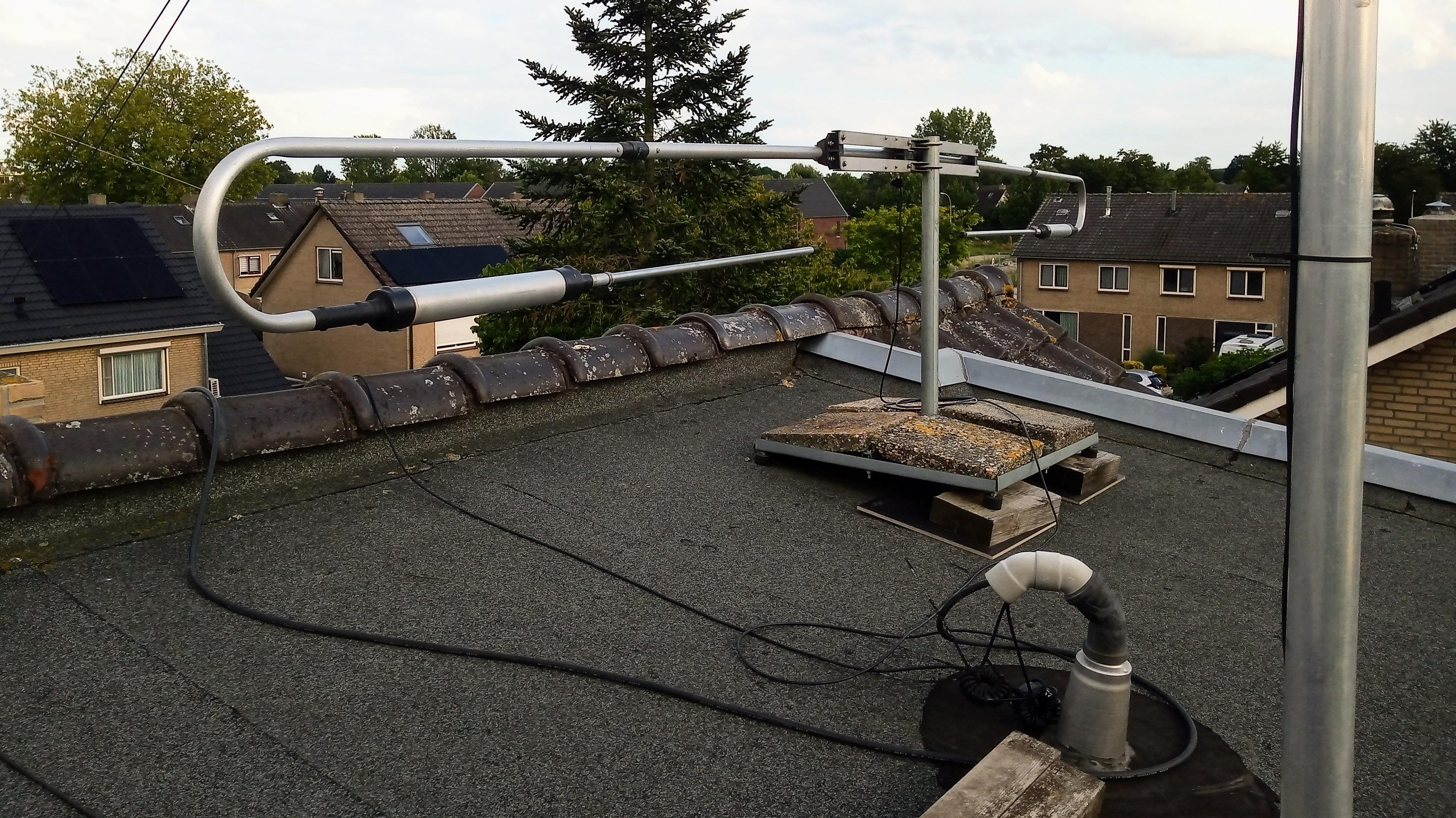
The SWR is very acceptable on all bands. Lowest SWR is a bit low on 10m and 15m but way below better than 1:1.5 on the entire band. I’ve tuned the end rods for 20m to have the lowest SWR in the middle of the band and despite of the two traps acting as loading coild on 20m the SWR is better than 1:2 on the entire band and seems to work fine on 14 MHz as well.
I haven’t put it on a rotator yet, it’s now pointing in NE / SW direction and I’ve let WSPR with 1W band hopping 20/15/10 since yesterday afternoon and, results are not bad at all:

Maybe this afternoon I will turn it in N/S direction to see if the picture looks very different.
73 Pleun
![]()


![]()