via Amateur Radio Daily: Radio Club of America Announces 2024 Award Recipients
22 September 2024 at 02:45

So you’re building a small dual-band Yagi and the instructions tell you to split the coax at the feedpoint. Stop right there. DX Engineering’s Michael Murphy, KI8R, shows you a better solution in the video below from DX Engineering’s YouTube channel.
Using a DX Engineering Flanged Feedpoint Connector and compatible hardware mounted to the boom will save you troubles down the road by keeping your coax connector water-tight. Plus, KI8R shares tips on how to seal all your antenna connectors to keep your coax free from damaging moisture using 3M Temflex 2155 Rubber Splicing Tape and 3M Scotch Super 33 Plus Vinyl Electrical Tape.
***
These handy parts provide a direct transition from the coaxial cable to feedpoint for Yagi, loop-fed arrays, rotatable dipoles, and other antennas that do not have a coaxial connector.
The worry of failed weatherproofing at the end of a stripped coax is eliminated for the 50-ohm beam or loop antenna feedpoint with stud terminals. Flanged feedpoint connectors allow direct connection of a PL-259 or N male terminated coaxial cable.
Choose from three versions of DX Engineering Flanged Feedpoint Connectors:
Only flanged versions can be mounted using the DXE-FFPM Feedpoint Connector Mounting Bracket and optional DX Engineering Stainless Mounting Clamps with Studs.
DX Engineering Flanged Feedpoint Connectors feature:
DX Engineering Flanged Feedpoint Connectors are also ideal for phased antenna pairs or multiples, on which a coaxial cable ferrite RF bead choke is desired at the feedpoint in place of a traditional balun. DX Engineering’s 40-bead DXE-FBC Ferrite Bead Choke Kit (below) fits on 0.405-inch diameter coax cable, like RG-213U and RG-8U, prior to connector installation.
For the 50-ohm beam or loop antenna feedpoint with stud terminals, we recommend using a combination of the DXE-FFPC-SO239 Flanged Feedpoint Connector, DXE-FFPM Mounting Bracket, and DXE-FBC Ferrite Bead Choke Kit.
The post DX Engineering Flanged Feedpoint Connectors—a Better Way to Attach Coax to Antennas that Don’t Have a Connector (Video) appeared first on OnAllBands.
It’s hard to keep up with all the new amateur radio gear you’ll find at DX Engineering! The latest products from leading manufacturers are being added weekly to the 30,000-plus ham radio items—from more than 175 top amateur radio providers—available at DXEngineering.com.
OnAllBands is dedicated to making sure you’re not missing out on that station addition that will improve your contesting scores, help you work more DX, upgrade your emergency preparedness, and enhance your 0verall enjoyment of the world’s greatest hobby.
DX Engineering has you covered with a bunch of new products you’ll want to add to your amateur radio must-have list, from premade coax assemblies to a new Icom handheld receiver. DX Engineering’s Michael Murphy, KI8R, highlights a few of the latest offerings in the video below.
Like what you see? Click on the links below for all the details.
The post New Products Spotlight: Antenna Tuners, Wireless Noise-Canceling Headphones, and More at DX Engineering (Video) appeared first on OnAllBands.
One of the great things about ham radio is the amazing variety of items that can be purchased to add more enjoyment to the world’s best hobby. Case in point: Today’s featured video on some of the latest products available at DXEngineering.com.
DX Engineering’s Michael Murphy, KI8R, highlights a few excellent station add-ons in his series, “What’s New at DXE,” including products from Chameleon Antennas, Eclipse Tools, RigExpert, Nifty Reference Guides, InnovAntennas, Comet Antennas, RT Systems Radio Programming Software, and DX Engineering.
Watch the video and find many more details on these featured products by clicking on the links below:
The post New Products Spotlight Video: Chameleon Remote Antenna Tuner, RigExpert Power Supply, and More appeared first on OnAllBands.
For more than two decades, the hams at DX Engineering have invested a great deal of time and brainpower toward enhancing the performance of Hustler BTV Series 4-, 5-, and 6-Band Vertical Antennas. This commitment has resulted in a slew of complementary DX Engineering-produced Hustler antenna products coupled with smart advice about installing ground radials for optimal results.
This combination of add-ons and operational wisdom continues to result in spectacular results for hams around the world. Here’s just one of many favorable opinions:
Five Stars (4BTV 4-Band HF Vertical Antenna): This antenna performs above and beyond what I expected! I hadn’t made any DX contacts in a very long time on the voice portion of the HF bands. After installing this per instructions and laying down 24 ground radials of various lengths due to confined space I easily made a contact into Germany through a pileup first try! Got a good 5-7 report with great audio! I also added the 17M add-on kit which performs flawlessly! Best antenna I have purchased!! Highly recommend this antenna if you are limited on space!
Ronald, DX Engineering Customer
Hustler BTV upgrades available at DXEngineering.com include the DX Engineering Direct Coax Feed Add-On Kit; BTV Series Antenna Packages, which come with OMNI-TILT![]() Base, DX Engineering patented Radial Plate, clamps, and hardware; DX Engineering Vertical Antenna Matching Network; and the 64-page instruction manual, which one customer called “the most important part of my antenna package.”
Base, DX Engineering patented Radial Plate, clamps, and hardware; DX Engineering Vertical Antenna Matching Network; and the 64-page instruction manual, which one customer called “the most important part of my antenna package.”
OnAllBands plans to cover all of the above in later posts, but first we’re checking out customer reviews of Hustler BTV Series add-on kits. In part one of this series, we explored the 17M add-on kit.
Today, we’ll be heading to the low bands for a look at the 80M add-on for the Hustler 4-BTV antenna (40/20/15/10M).
The 80M add-on is tunable for operating across a small segment of the 75/80m band with an SWR of 1.5:1 or less. Larger frequency excursions are easily made by lowering the antenna and adjusting the length of the top rod. A DX Engineering DXE-TB-3P Tilt Base Antenna Mounting System (sold separately) makes this a simple job. A good SWR meter or antenna analyzer will allow you to check the overall performance of the antenna while making final adjustments.
The DX Engineering 80M add-on kit requires no disassembly of your existing antenna. Simply add one of these kits to the top of the existing installation, make some minimal tuning adjustments, and enjoy getting on the air with an additional band. These kits come complete with Hustler RM75/80 resonator with large corona ball whip; Allen wrench for the two Allen set screws on the 80M resonator; and three-bladed spider assembly (above).
Five Stars: Excellent! Simple to install and tune. Best reports ever with locals. Then worked Puerto Rico first night.
James, DX Engineering Customer
***
Five Stars: Easy to install and tune. And nice to get all the needed parts in one kit with good instructions.
Aaron, DX Engineering Customer
***
Five Stars: Easy to install, especially if you have the Omni-Tilt base on your 4BTV. Tuning was simple, took about three tries to get it centered on the frequency I wanted using the MFJ-223 analyzer. Performance with 32 radials is not bad. Expect about 45-50KHZ of usable 2:1 SWR bandwidth.
Samuel, DX Engineering Customer
***
Arrived quickly, well packed. 80M resonator and whip in one box, three-leg spider in second box shipped separately. Easy to install on my 5+ year old 4BTV. Required a bit of retuning the vertical, mostly 40M (top section was shortened a bit). SWR about 1.5:1 80-40-20M and 1.2:1 15-10M with my 36 radials. Have had a few 80M QRP QSOs so far. Signal reports about one S unit weaker than my full length 80M dipole—not bad for a shortened radiator. QRO probably better.
Paul, DX Engineering Customer
The post What Does the Customer Say? Hustler BTV Series Vertical Antenna Add-On Kits: Part 2, 80M Add-On Kit appeared first on OnAllBands.
OnAllBands has been taking a close look at products that can help you get more out of your Hustler 4BTV, 5BTV, and 6BTV vertical antennas. We’ve got quite a bit of ground to cover, so we’re starting with the DX Engineering add-on kits that let you easily and effectively expand coverage. Check out this article on the Hustler BTV Series 17M Add-On Kit. Later this month we’ll be exploring what operators say about the 80M add-on kit.
Today, we turn our attention to the latest addition to DX Engineering’s lineup of devices that have turned the Hustler BTV verticals into an affordable and proven DXing juggernaut for hams around the globe, especially those dealing with limited space and HOA restrictions.
The updated DX Engineering 12 Meter Add-On Kit for Hustler 4BTV, 5BTV, or 6BTV HF Vertical Antennas (DXE-AOKC-12M) adds 12 meter coverage (24.890 through 24.990 MHz) without giving up existing band coverage. Simply install the kit, check the tuning, make minimal tuning adjustments, and you’re on the air with an additional band.
Users on eHam.net have called the DXE-AOKC-12M a “great product for the money,” “first-rate made,” “a superior product that performs, “very easy to assemble,” and “a straightforward way to add 12M to the Hustler without it looking like a Rube Goldberg contraption.” Check out all the reviews at eHam.net.
The RF power handling of the DXE-AOKC-12M 12 Meter Add-On Kit is conservatively rated for 1,500 watts PEP SSB, 1,000 watts CW, and 375 watts RTTY and Digital modes (including FT8) at an antenna SWR of 2:1 and below. This rating is for 12 meters only; it does not apply to BTV antenna trap or resonator frequencies where the use of less power is advised.
The 17M and 12M kits work together because they do not interact with each other. Further, installing them on your BTV antenna will not drastically affect other bands. The 17M and 12M kits match each other, except for the coil on the 17M, and they add negligible wind loading to the antenna. The kits can mount on opposite sides of the Hustler BTV vertical and may be installed at the same time or at different times.
The above photo shows the following:
TIP: The use of the OMNI-TILT base is recommended for BTV ground mounting when both 17M and 12M kits are installed.
The 12M add-on kit includes:
Installation of the DXE-AOKC-12M can have the effect of narrowing the SWR bandwidth of 20, 15, and 10M—a reasonable tradeoff for adding the extra band. After the 12M kit is installed and tuned, any required shift to the usable SWR frequency ranges on those bands can be accomplished by trap sleeve repositioning on the respective band trap. SWR may be optimized for CW and Digital or SSB segments by careful trap sleeve tuning adjustments.
For more about tuning, assembly instructions, and further details, read the DXE-AOKC-12M manual. Visit DXEngineering.com to order this impressive Hustler upgrade.
The post Product Spotlight: DX Engineering 12 Meter Add-On Kit for Hustler 4BTV, 5BTV & 6BTV Vertical Antennas appeared first on OnAllBands.
It has become apparent over the years that many folks who love everything about ham radio also love their cars, trucks, motorcycles, and ATVs. This is supported by the fact that there are plenty of DX Engineering customers who also do their shopping for suspension systems, exhaust tips, piston sets, and fuel injectors at Summit Racing Equipment. In fact, we’ve lost count of the number of letters we’ve received from those who relish both turning corners and turning knobs.
For those who don’t already know, Summit Racing has been the parent company of DX Engineering ever since the aftermarket automotive parts giant acquired the ham radio manufacturer in 2000. (Look for much more about DX Engineering’s 25th Anniversary celebration in the months ahead.)
DX Engineering shares headquarters with Summit Racing in Tallmadge, Ohio, near Akron. The updated DX Engineering Amateur Radio Showroom is housed inside the Summit Racing Retail Superstore at the same location. Ham radio gear can also be purchased at the Summit Racing retail store in Sparks, Nevada.
Need a transceiver and a transmission? A set of radials for your Hustler BTV vertical antenna and some radials for your 1972 Chevelle? A thrust bearing and a main rod bearing? A brake rotor and a heavy-duty rotator? You’ll uniquely find them all under the same roof.
How cool and convenient is that?
For those who can’t make it to the stores in Ohio and Nevada, both Summit Racing (SummitRacing.com) and DX Engineering (DXEngineering.com) make ordering incredibly fast and easy online. Both companies are widely recognized for providing fast shipping (more about speed below) and the most knowledgeable and responsive customer/technical support in their respective industries.
Check out the DX Engineering and Summit Racing decals on Jarvis Island in August 2024! In the photo, George Wallner, AA7JV, member of the offshore crew of the N5J Jarvis Island DXpedition, sets up a self-contained Rig in a Box station on one of the rarest DXCC entities on the planet. The DXpedition was sponsored by DX Engineering. Also notice the VP Racing jug, available at Summit Racing, along for the trip.
At first inspection, automotive enthusiasts and ham radio aficionados may seem to have little in common. But look closer. The hobbies and the people who are passionate about them share a lot more than you might think.
Summit Racing is appropriately known as “The World’s Speed Shop®,” the place where you can find millions of go-fast parts to soup up your ride for the street, dirt track, road course, or drag strip.
While transceivers don’t come equipped with a finish-line parachute, speed is still very much a part of the hobby for scores of amateur operators. Many hams were first intrigued by the idea that their transmissions could reach across the globe thanks to radio waves traveling at the speed of light—186,000 miles per second (a tad quicker than your average quarter-mile pass). Elite CW practitioners hone their skills to reach mind-boggling speeds up to 60 WPM. Like a road race, marathon radiosport contests, such as the 24-hour World Radiosport Team Championship, become a test of both operating speed and endurance. Other ham radio activities, such as direction-finding competitions, depend on quick wits and speed when searching for hidden transmitters.
Finally, we know gearheads and hams alike don’t like to wait around their garages and shacks for parts to arrive—so you can expect speedy delivery of what you need—when you need it.
Whether completely restoring a classic, modifying a late-model muscle car, or creating a one-of-a-kind rat rod, there is nothing that makes a gearhead happier than wrenching on their latest project—permanently oil-stained fingernails be darned! Hams are no different. While getting on the air may be the ultimate reward, the satisfaction of installing an antenna, adding a new rotator, or building a homebrew amplifier ranks high for the hands-on ham.
Ask a gearhead or a ham how they spent their early years and you’ll hear stories of disassembled vacuum cleaners and radios, spare parts strewn across living rooms, and angry parents (though secretly proud) admonishing them for not asking first. The obsession to find out what makes things tick runs deep in both hobbies.
Even tasks like prepping and installing connectors on coaxial cable, weatherproofing cable connections, properly grounding amateur radio equipment, and spring station maintenance mean more time spent doing ham radio stuff—always a good thing. And like most gearheads and their cars and trucks, most amateurs view their stations as works in progress, always with an eye on the next big improvement or strategic tweak.
Ask a certain type of gearhead “How many vehicles are enough?” or a similarly inclined ham “How many radios are enough?” and you’re likely to get a shrug. Why? Because there simply isn’t a way to quantify an answer for those whose thirst for rides and rigs have no boundaries.
As of January of 2024, it was reported that Jay Leno’s vehicle collection consisted of over 180 cars and 160 motorcycles. Jerry Seinfeld’s cache of cars exceeds 150, including more than 40 Porsches. For those less monetarily endowed, it’s still difficult to turn down a project vehicle regardless of condition or space limitations. Same goes for hams who can’t pass by a hamfest flea market without adding another vintage rig to their collections or peruse DXEngineering.com without adding the latest SDR model and companion gear to their shopping cart.
It’s no wonder that DX Engineering sells a T-shirt that reads, “Just One More Radio, I Promise” and Summit Racing sells one that reads, “Just One More Car, I Promise.”
Attend a car show or a day at the track and you’ll discover that competitiveness and camaraderie go hand in hand. Trophies and trips to the winner’s circle are nice, but longtime gearheads will tell you it’s the friendships with other enthusiasts that count most at the end of the day. Need proof? Listen to a couple of strangers become fast friends as they ease into a “bench racing” give-and-take or share stories of the “cars that got away.” Hams have the added benefit of being able to make friends from all parts of the world simply by getting on the air and calling CQ. Goodwill is at the core of what it means to be an amateur operator, whether hanging out with your club on Field Day or rag-chewing with an operator thousands of miles away.
***
We’d love to hear from all the ham/gearheads out there! Tell us about what you think is the crossover appeal of getting on the air and putting power to the pavement.
The post Hams & Gearheads: The Strong Connection Between DX Engineering & Summit Racing Customers appeared first on OnAllBands.
It’s a sad truth: Many people in the ham radio community never explore the opportunities afforded to them by their Technician license. You pored over the ham radio study guide, learned the basic math, asked your Elmer a million questions, and passed the test with flying colors.
But that’s as far as things progressed. It’s a common story: Life gets in the way.
While there are many reasons why new hams don’t make use of their first license, one of them isn’t a lack of opportunity to have a blast on the air. A Tech license opens up a vista of privileges, some of which are the coolest and most valuable among the long list of ham radio activities.
In today’s OnAllBands video, Michael Murphy, KI8R, DX Engineering customer/technical support specialist, shows some of the ways you can take advantage of punching your amateur radio ticket, along with encouraging words and practical advice on making your operating goals a reality.
But the question, “I just got my license. What’s next?” doesn’t just apply to new operators, as KI8R explains. Moving up the ham radio licensing ladder to General and Amateur Extra brings new opportunities but also may elicit more questions about how you may want to move into other areas of interest.
Enjoy the video below. And if you’re new to the hobby, welcome aboard! We can’t wait to hear you on the air!
We also recommend this excellent article by blogger Sean, KX9X, “Beyond Your Local Repeater: 15 Things to Do with a Technician License.”
Need help getting your first station together? DX Engineering offers handheld, mobile, base station, Go Box, and POTA ham radio getting started packages that take the worry out of choosing the right transceivers, antennas, and station components for your goals and budget.
The post So You Got Your Ham License? Here’s How to Start Enjoying Amateur Radio. (Video) appeared first on OnAllBands.
The DX Engineering Logo UltrAtomic® Wall Clock features dramatically improved reception and reliability, allowing you to automatically set and keep time, even at daylight saving time changes.
Excellent readability and attractive styling make this DX Engineering 14-inch analog clock a great addition to any amateur radio station, office complex, school, or home.
The UltrAtomic receives the enhanced phase modulated WWVB broadcast signal introduced by the National Institute of Standards and Technology (NIST) in 2012. This advanced technology allows the radio time signal to “break through” barriers like cement walls, unlike previous PWM-only atomic clocks.
WWVB is a time signal radio station near Fort Collins, Colorado. It is co-located with WWV, a time signal station established in 1919 that broadcasts in both voice and time code on different shortwave frequencies. You can read a brief history of ham radio and WWV, WWVH, and WWVB in this OnAllbands article by Mark, K8MSH.
This is the DX Engineering version of the La Crosse Technology wall clock that was the first on the market to be based on this enhanced broadcast. The UltrAtomic clock operates even in the harshest conditions, such as when the signal-to-noise ratio interferes with radio-controlled clock reception using the legacy AM signal broadcast.
UltrAtomic technology digitally processes the received signal via an integrated circuit within the clock. It leverages the advanced modulation scheme and new data encoding. The reception reliability of the technology has been validated in the most challenging locations and scenarios and has been demonstrated successfully throughout North America.
The clock lets you select any time zone with a custom setting, especially UTC/GMT. Now you can enjoy UltrAtomic accuracy while viewing any time zone around the world.
The phase modulated WWVB broadcast includes a notification for daylight saving time transitions well ahead of when they occur. The clock reads and stores this information and, at the appropriate instance, automatically advances the hands one hour in the spring and eleven hours in the fall (to move back one hour), even if the signal is not received on the day of the transition.
Other features include:
The post New Product Spotlight: DX Engineering Logo UltrAtomic® Wall Clock appeared first on OnAllBands.
Premiered at Dayton Hamvention® 2024, the DX Engineering High CMI (Common Mode Impedance) Receive Feedline Choke (DXE-RXFC-75) achieves exceptionally high isolation between the input and output connector shields to effectively block common-mode RF noise and unwanted signals that collect on 75-ohm receive antenna feedlines. The choke—the result of ongoing work by DX Engineering’s research and development team—makes an ideal choice for typical and advanced low-band receive antenna systems.
Before we get into the nuts and wires of the DXE-RXFC-75, you may be asking, “What exactly is a common-mode current and why is it harmful?
For our answer, we turn to Ward Silver, N0AX, who explains it in his OnAllBands article, “Baluns and Common-Mode Impedance: How Much is Enough?”
“In this article, common-mode current, or CMC, means current flowing on the outside of a coaxial cable shield. Because of the skin effect, the inside and outside surfaces of the shield can carry different currents. Fields from current on the outside (the common-mode current) are not canceled by fields from an opposing current as they are for the shield and center conductor currents inside the coax. This means common-mode current will radiate like any current on a wire, and external fields picked up by the shield from the transmitted signal or from other signals or noise will create common-mode current on the shield.”
Ward Silver, N0AX
So why block CMC? As the article above notes, blocking CMC reduces re-radiation that distorts the radiation pattern and reduces re-radiation near equipment that can cause RFI.
Covering 100 kHz through 30 MHz, the DXE-RXFC-75 Receive Feedline Choke exhibits very high common mode impedance (see specs below), typically over 7,500 ohms across the 160, 80, and 40 meter bands. It features DC pass capability up to 700 mA at 13.8VDC, with extremely low SWR and negligible insertion loss.
The DXE-RXFC-75 has a nominal impedance of 75 ohms with Type-F connectors to prevent accidental connection to transmitting equipment. The choke is built into a two-inch square plastic box, 1.5 inches deep, with non-directional input and output F connectors on opposite sides. It’s permanently sealed to prevent changes to the precisely adjusted components by physical shock or internal moisture. The top and bottom sides each have 7/16-inch flanges with 3/16-inch holes for mounting (hardware not included).
Nominal Common Mode Impedance by Frequency (Approximate)
Insertion Loss
VSWR: <1.25:1 maximum; 1.06:1 at 7 MHz, nominal
Find more baluns, UNUNS, and feedline chokes—including DX Engineering’s top-of-the-line Maxi-Core® 20 baluns and chokes—at DXEngineering.com.
The post New Product Spotlight: DX Engineering High CMI Receive Feedline Choke appeared first on OnAllBands.
Plus New Cable Gripper for RG-400 Size Coax
Wouldn’t it be great if all connectors were uniform, and you didn’t have to worry about A fitting into B, and B fitting into C? As any ham knows, variety is the spice of building and maintaining an amateur radio station. It’s just one of the aspects of the hobby that makes being an operator endlessly interesting and challenging.
While DX Engineering enjoys the challenges, we also relish the opportunity to make life a bit simpler for our fellow hams by coming up with solutions to common problems, which is the subject of this blog entry.
Problem: What if two devices, say, your transceiver, switch, meter, lightning protector, or antenna, have opposite female connectors—one type-N and the other SO-239?
Solution: DX Engineering 400MAX Type-N to PL-259 Low-Loss 50-Ohm Coaxial Adapter Cable Assemblies
Available in lengths up to 300 feet (3, 6, 50, and 100 feet assemblies are in stock, other lengths are custom-made by special order), these assemblies make an excellent choice over less-reliable straight adapters. The cable assemblies are:
Both connectors feature machine-crimped shields with 360 degrees of complete mechanical and electrical contact for maximum reliability. PL-259 center pins are hand-soldered, and Type-N center pins are machine-crimped by trained assembly techs to assure a proper connection.
Further, Next Generation PL-259 connectors feature:
You can also order the specific length of 400MAX coaxial cable—and a variety of other cables with the connectors you desire—by selecting the specific length (up to 300 feet) and connector types at DX Engineering’s Custom Cable Builder at DXEngineering.com. DX Engineering cable can also be purchased in bulk spools of 500 and 1,000 feet or by the foot.
DX Engineering is pleased to introduce a new hinged coaxial cable gripper (DXE-CGH-195) to add to its impressive lineup of coax prep tools designed to firmly hold coaxial cable while you prepare it for connector installation.
The device provides a dramatically improved grip on DXE-8U, DXE-400MAX, DXE-11U, DXE-213U, standard RG-8 or other RG-8U size (0.405-inch nominal) coaxial cables.
Featuring a bumpy finish on the outside and grooved surface on the inside to maintain a non-slip grip, the tool is ideal for use with the DXE-UT-8213 Coaxial Cable Preparation Tool and the DXE-UT-80P and DXE-UT-80N Connector Installation Tools for two-piece solder-on PL-259 and Type-N connectors. The two halves fit together with hinges and a strong steel spring that aids in grip and alignment. DX Engineering gripper tools also take the hassle out of installing crimp connectors.
Find the full lineup of DX Engineering cable grippers and gripper/stripper combos at DXEngineering.com, along with coax prep tool kits for soldered and F connectors and coax preparation tools and tool kits for installing crimp connectors.
The post Product Spotlight: DX Engineering 400MAX Type-N to PL-259 Low-Loss 50-Ohm Coaxial Adapter Cable Assemblies appeared first on OnAllBands.
I get quite a few emails from readers of my blog asking how my QO-100 satellite station is put together and so, I thought perhaps now is a good time to put together an article detailing the complete build.
My QO-100 satellite ground station is built around my little Icom IC-705 QRP transceiver, it’s a great little rig and is ideal for the purpose of driving a 2.4Ghz transverter/up-converter.
Of course all the software used for the project is Opensource and freely available on the internet.
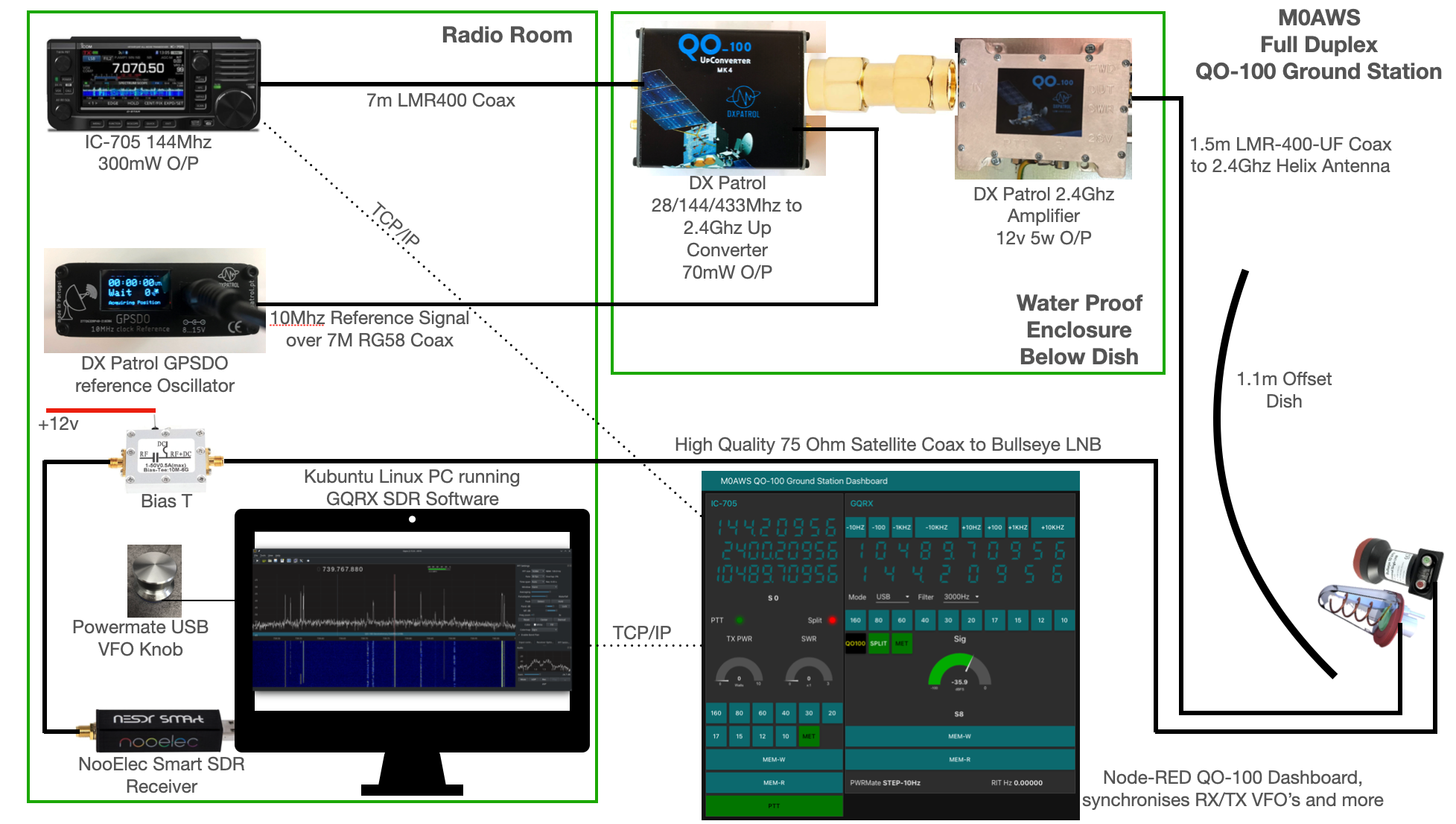
The station comprises of the following building blocks:
To get a good clear view of the QO-100 satellite I have the dish mount 3.2m above the ground. This keeps it well clear of anyone walking past in the garden and beams the signal up at an angle of 26.2 degrees keeping well clear of neighbouring gardens.
The waterproof enclosure below the dish houses all the 2.4Ghz equipment so that the distance between the feed point and the amplifier are kept to a minimum.
The DXPatrol amplifier is spec’d to run at 28v/12w or 12v/5w, I found that running it at 28v produced too much output for the satellite and would cause the LEILA alarm on the satellite to trip constantly. Running the amp at 12v with a maximum of 5w output (average 2.5-3.5w) is more than enough for me to have a 5/9+10 signal on the transponder.
The large 1.1m dish gives me quite an advantage on receive enabling me to hear the very weak stations with ease compared to other stations.
The photo above shows the 2.4Ghz equipment mounted in the waterproof enclosure below the dish. This photo was taken during the initial build phase before I rewired it so, the amplifier is shown connected to the 28v feed. To rewire the amp to 12v was just a matter of removing the 28v converter and connecting the amp directly to the 12v feed instead. This reduced the output from a maximum of 12w down to a maximum of 5w giving a much better (considerate) level on the satellite.
It’s important to keep all interconnects as short as possible as at 2.4Ghz it is very easy to build up a lot of loss between devices.
For the connection from the IC-705 to the 2.4Ghz Up-Converter I used a 7m run of
LMR-400 coax cable. The IC-705 is set to put out just 300mW on 144Mhz up to the 2.4Ghz converter and so it’s important to use a good quality coax cable.
Once again the output from the 2.4Ghz amplifier uses 1.5m of LMR-400-UF coax cable to feed up to the 2.2 turn Icecone Helix Antenna mounted on the dish. This keeps loss to a minimum and is well worth the investment.
The receive path starts with a Bullseye LNB, this is a high gain LNB that is probably one of the best you could use for QO-100 operations. It’s fairly stable frequency wise but, does drift a little in the summer months with the high temperature changes but, overall it really is a very good LNB.
The 12v feed to the LNB is via the coax and is injected by the Bias-T device that is in the radio shack. This 12v feed powers the LNA and associated electronics in the LNB to provide a gain of 50-60dB.
From the Bias-T the coax comes down to the NooElec SmartSDR receiver. This is a really cheap SDR device (<£35 on Amazon) based on the RTL-SDR device but, it works incredibly well. I originally used a Funcube Dongle Pro+ for the receive side however, it really didn’t handle large signals very well and there was a lot of signal ghosting so, I swapped it out for the NooElec SDR and haven’t looked back since.
The NooElec SmartSDR is controlled via the excellent Opensource software GQRX SDR. I’ve been using GQRX SDR for some years now and it’s proven itself to be extremely stable and reliable with support for a good number of SDR devices.
To enhance the operation of the SDR device I have added a Griffin Powermate VFO knob to the build. This is an old USB device that I originally purchased to control my Flex3000 transceiver but, since I sold that many moons ago I decided to use it as a VFO knob in my QO-100 ground station. Details on how I got it working with the station are detailed in this blog article.
Having the need for full duplex operation on the satellite this complicates things when it comes to VFO tracking and general control of the two radios involved in the solution and so I set about creating a QO-100 Dashboard using the great Node-RED graphical programming environment to create a web app that simplifies the management of the entire setup.

The QO-100 Dashboard synchronises the transmit and receive VFO’s, enables split operation so that you can transmit and receive on different frequencies at the same time and a whole host of other things using very little code. Most of the functionality is created using standard Node-RED nodes. More info on Node-RED can be found on the Opensource.radio Wiki or from the menu’s above.
I’ll be publishing an article all about the QO-100 Dashboard in the very near future along with a downloadable flow file.
I’m extremely pleased with how well the ground station works and have had well in excess of 500 QSO’s on the QO-100 satellite over the last last year.
More soon …
With permission from the Canadian Department of Fisheries and Oceans, the 10-operator CY9C DXpedition team is scheduled to put St. Paul on the air August 26 to September 5 from the windswept and treeless Northeast Island site, just off the coast of Nova Scotia.
The team of experienced hams, many of whom participated in the highly successful CY0S Sable Island DXpedition in March 2023, plan to be active on 160-6M, employing Yagis on 20-6M and elevated sloping dipoles and verticals on the low bands. There should be a good mix of modes available for filling bands (CW, SSB, RTTY, FT8, EME, Satellites), with an emphasis on Morse code contacts. Uninhabited and rarely visited St. Paul Island is approximately three miles long and a mile wide.
The island features an automated solar-powered lighthouse built in 1962—the third lighthouse which has served watercrafts between the Gulf of St. Lawrence and the Cabot Strait. Lighthouse chasers will be hoping to add this to their conquests (STP-002), as well as POTA (CA-0122) and IOTA (NA-094) enthusiasts.
The island is encircled by foreboding rock-faced cliffs, which will require the CY9C team to use two helicopters to transport gear and team members to the operating site.
Find updated information at CY9C’s official website. St. Paul Island ranked as the 52nd Most Wanted DXCC Entity as of May, per Clublog.
***
DX Engineering was a proud sponsor of the CY9C 2016 St. Paul DXpedition. The company provided a range of gear used on the island, including the Butternut HF9V 9-Band Vertical Antenna.
Two operators from that DXpedition, Jay, K4ZLE, and Murray, WA4DAN, are also scheduled to operate in this latest venture. For CY9C 2024, DX Engineering has provided the following equipment for a Beverage antenna system:
DX Engineering Beverage Antenna System: This single-wire, single-direction beverage feed system (100 kHz to 30 MHz) designed by W8JI is immune to the strong signal overload and core saturation common in multi-transmitter environments, making it ideal for low-band DXers. It employs an isolated-winding matching-transformer system to significantly increase the signal-to-noise ratio in Beverage and other high-impedance antennas.
DX Engineering RPA-2 Modular Receive Preamplifier: This preamp delivers low internal noise and is optimized for the 300 kHz to 35 MHz range. The device is designed to help you hear the weakest signals without artificially raising the noise. Robust components allow this preamplifier to withstand high signal levels while providing superior dynamic range and third-order intercept performance that equals or exceeds most receiver and transceiver front-ends.
DX Engineering Beverage Termination Resistors
Check in with OnAllBands for more articles on the CY9C 2024 St. Paul Island DXpedition as the date nears.
The post DX Engineering Lends Support to Upcoming DXpedition to St. Paul Island appeared first on OnAllBands.
As we’ve said many times at OnAllBands, if you want the real scoop on a ham radio product, ask someone who has used the device to make QSOs during a heated contest, fight through a pileup while chasing a rare station, operate from a temporary setup in the middle of a park, or get on the air through their local repeater.
Listening to honest opinions from folks who have spent their hard-earned money on equipment is a smart step in making sure you’re buying products that will deliver as advertised. You’ll find many opinions online and at DXEngineering.com, where customers rate their purchases from one to five and often include a detailed explanation of how they use the product, their advice on installation and operation, and the results they received.
Sometimes the reviewer will offer informed criticism or make a suggestion for an upgrade—something the team at DX Engineering takes very seriously when assessing our own branded products to make them easier to use and more efficient. In short, your thoughts on what you buy from us matter. Today, we’ll be looking at reviews of the BTV-AOKC-17M DX Engineering 17M Add-On Kit for Hustler 4/5/6-BTV Vertical Antennas
Let’s start with this link to a detailed eham.net review by WB0KWJ of the 17 meter add-on kit, which notes that the kit is “easy to assemble, works well, and is worth the price.”
Rather than homebrewing an add-on that may or may not work, the review says you’ll save a lot of time (the reviewer was able to use the kit within an hour of opening the box) with a “tested, effective design made of weather-resistant materials.”
***
Five Stars: “Easy to add to my 4-BTV. Has a flat SWR without tweaking and did not affect SWR on the other bands. Worked seven countries with 100 watts in the first week, so I’m happy.”
David, DX Engineering Customer
Five Stars: “This is a very simple add-on kit made of high-quality materials with excellent assembly and install instructions. After installation on my 4-BTV, no tuning was needed for 17m. I was satisfied with the 1.3:1 SWR across the band. Also, the add-on did not alter any other bands as far as SWR or performance. I have the antenna on a DX Engineering OMNI-TILT so install was simple. As far as cost, price is in the mind of the buyer; yeah, DIY will be cheaper, but the convenience and quality of this kit makes it worth it in my mind. Now with the 30m and 17m add-on, I have a very low visual impact installation that performs way better than I thought it could on every band.”
Stephen, DX Engineering Customer
***
Five Stars: “Assembled and installed on my Hustler 6-BTV in less than two hours. Used the initial settings derived by the 12m kit, and out of the box I had a 1.5:1 and lower SWR across the band. This install actually dropped my already good SWR across most of the bands on my antenna. After the install I proceeded to establish a QSO with a DXpedition in Uganda in FT8 with 35 watts. Fantastic!”
Mark, DX Engineering Customer
***
Five Stars: “Followed the instructions that came with it, got it installed, and checked the SWR across the band and it was below 1.5 across it. Works great.”
Dennis, DX Engineering Customer
***
Find complete details of the DX Engineering 17M Add-On Kit for Hustler BTV Series Vertical Antennas at DXEngineering.com, along with Hustler vertical antennas, antenna packages, resonators, antenna matching network, replacement parts, and BTV add-on kits for 80M, 60M, 30M, and 12M, which we’ll discuss in future OnAllBands posts.
The post What Does the Customer Say? Hustler BTV Series Vertical Antenna Add-On Kits: Part 1, 17M Add-On Kit appeared first on OnAllBands.
![]()
![]()
![]()
Many years ago I had an MFJ-259B antenna analyser that I used for all my HF antenna projects. It was a simple device with a couple of knobs, an LCD display and a meter but, it provided a great insight into the resonance of an antenna.
Today things have progressed somewhat and we now live in a world of Vector Network Analysers that not only display SWR but, can display a whole host of other information too.
Being an avid antenna builder I’ve wanted to buy an antenna analyser for some time but, now that I’m into the world of QO-100 satellite operations using frequencies at the dizzy heights of 2.4GHz I needed something more modern.
If you search online there are a multitude of Vector Network Analysers (VNAs) available from around the £50.00 mark right up to £1500 or more. Many of the VNAs you see on the likes of Amazon and Ebay come out of China and reading the reviews they aren’t particularly reliable or accurate.
After much research I settled on the JNCRadio VNA 3G, it gets really good reviews and is very sensibly priced. Putting a call into Gary at Martin Lynch and Sons (MLANDS) we had a long chat about various VNAs, the pros and cons of each model and the pricing structure. It was tempting to spend much more on a far more capable device however, my sensible head kicked in and decided many of the additional features on the more expensive models would never get used and so I went back to my original choice.
Gary and I also had a long chat about building a QO-100 ground station, using NodeRed to control it and how to align the dish antenna. The guys at MLANDS will soon have a satellite ground station on air and I look forward to talking to them on the QO-100 transponder.
Getting back to antenna analysers, I purchased the JNCRadio VNA 3G from MLANDS at £199.96 + postage and have been trying it out on a couple of antennas here at the M0AWS QTH.
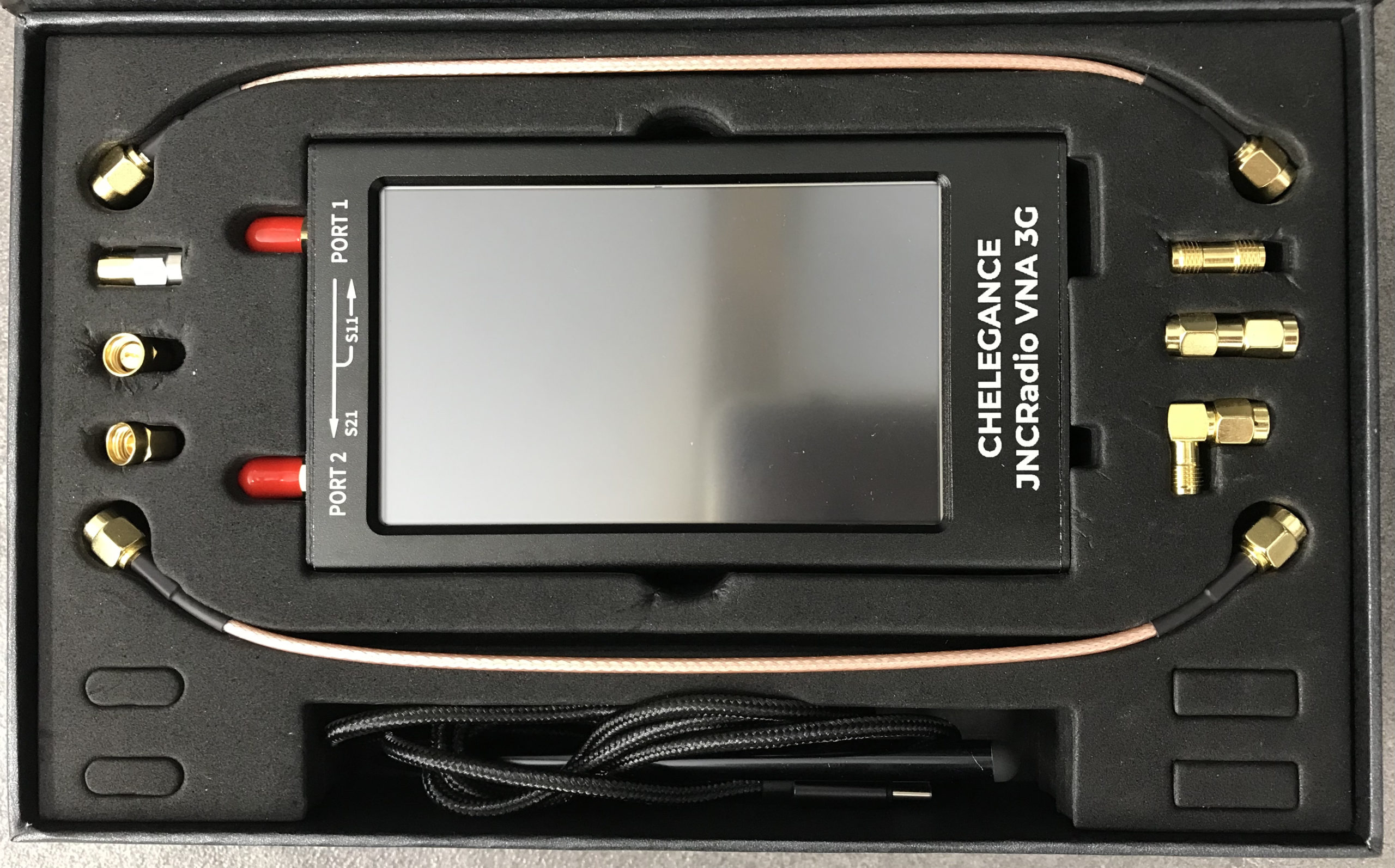
Initially I wanted to check the SWR of my QO-100 2.4GHz IceCone Helix antenna on my satellite ground station to ensure it was resonant at the right frequency. Hooking the VNA up to the antenna feed was simple enough using one of the cables provided with the unit and I set about configuring the start and stop stimulus frequencies (2.4GHz to 2.450GHz) for the sweep to plot the curve.
The resulting SWR curve showed that the antenna was indeed resonant at 2.4GHz with an SWR of 1.16:1. The only issue I had was that in the bright sunshine it was hard to see the display and impossible to get a photo. Setting the screen on the brightest setting didn’t improve things much either so this is something to keep in mind if you plan on using the device outside in sunny climates.
(My understanding is that the Rig Expert AA-3000 Zoom is much easier to see outside on a sunny day however, it will cost you almost £1200 for the privilege.)
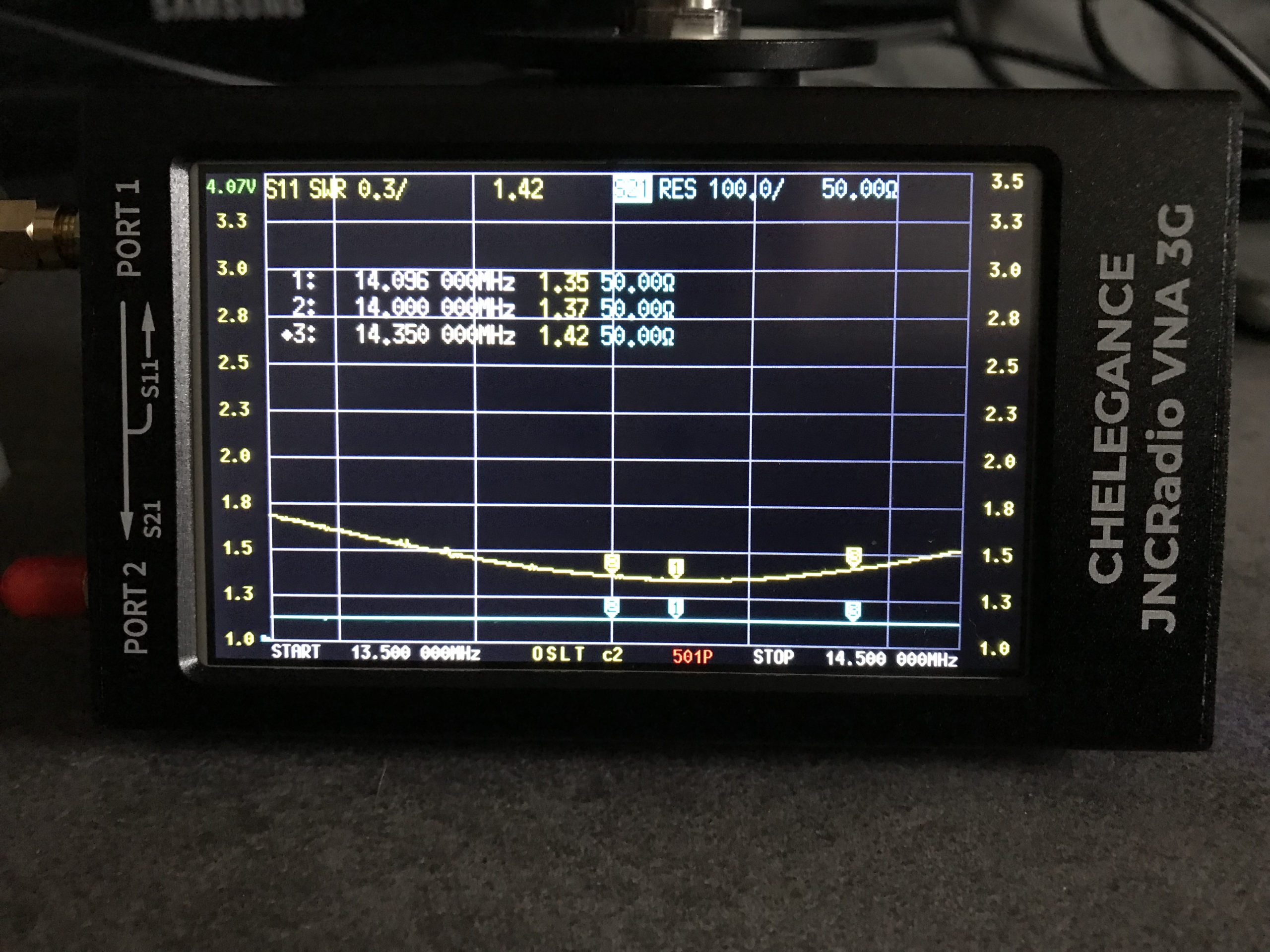
A couple of days later I decided to check the SWR of my 20m band EFHW vertical antenna. I’ve known for some time that this antenna has a point of resonance below 14MHz but, the SWR was still low enough at the bottom of the 20m band to make it useable.
Hooking up the VNA I could see immediately that the point of resonance was at 13.650Mhz, well low of the 20m band and so I set about shortening the wire until the point of resonance moved up into the band.
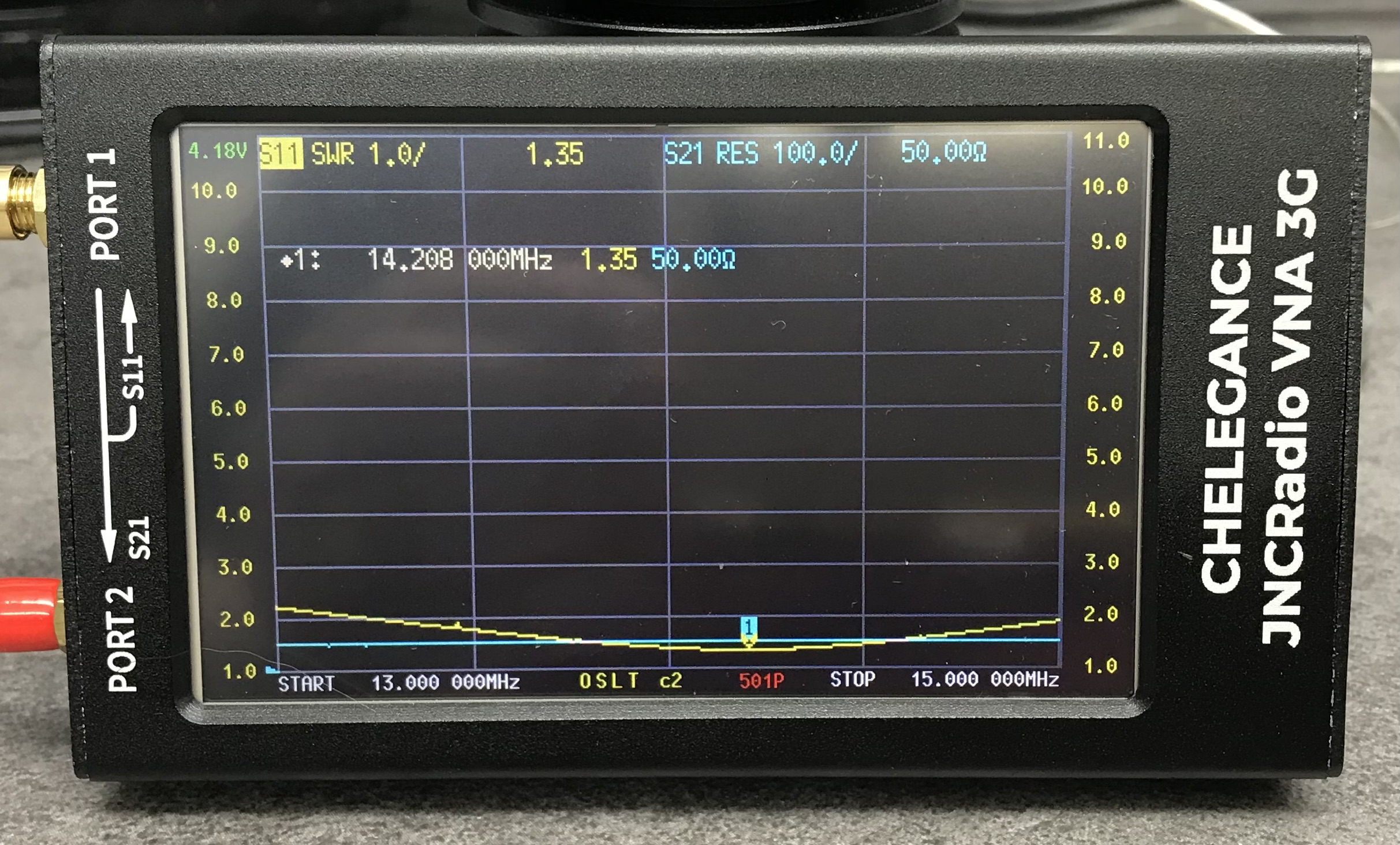
With a little folding back of wire I soon had the point of resonance nicely into the 20m band with a 1.35:1 SWR at 14.208Mhz. This provides a very useable SWR across the whole band but, I decided I’d prefer the point of resonance to be slightly lower as I tend to use the antenna mainly on the CW & FT4/8 part of the band with my Icom IC-705 QRP rig.
Popping out into the garden once more I lengthened the wire easily enough by reducing the fold back and brought the point of resonance down to 14.095Mhz.
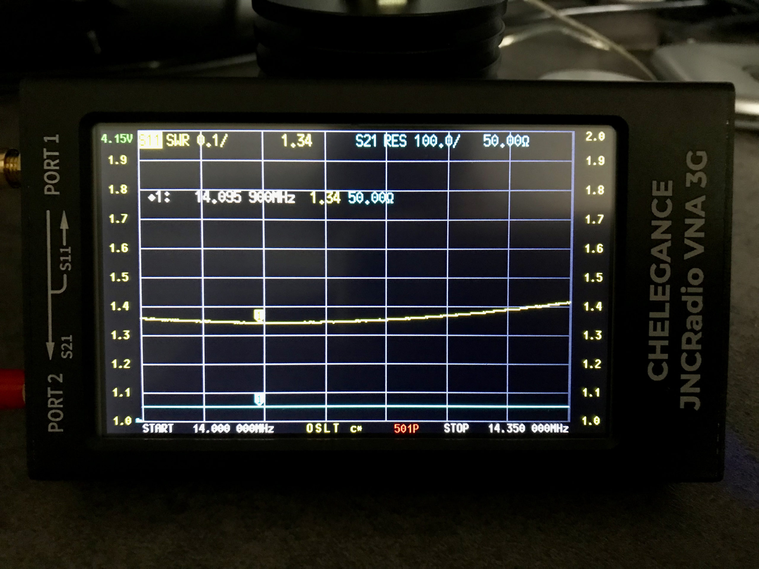
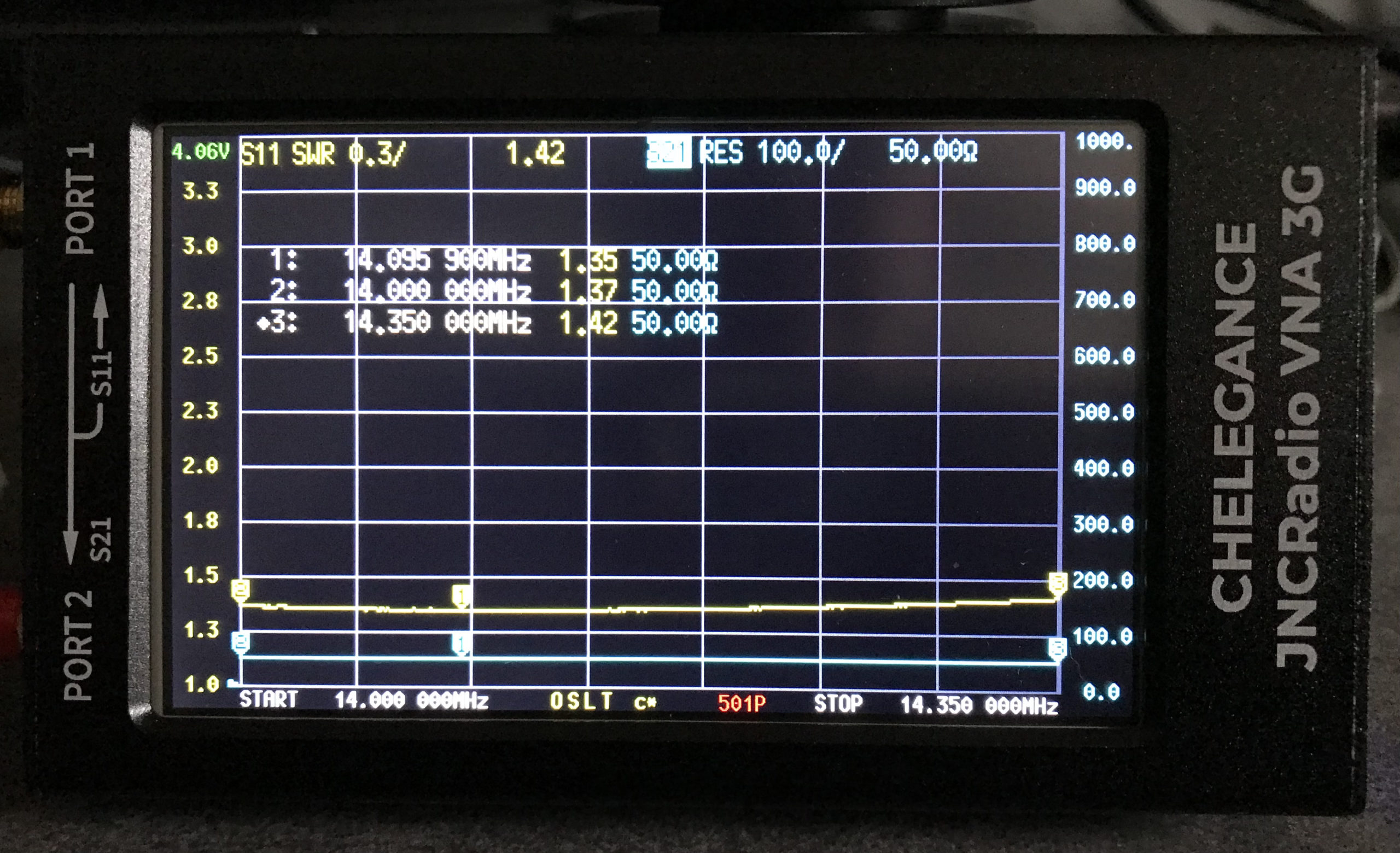
The VNA automatically updated the display realtime to show the new point of resonance on the 4.3in colour screen. I also altered the granularity of the SWR reading on the Y axis to show a more detailed view of the curve and reduced the frequency range on the X axis so that it showed a 14Mhz to 14.35Mhz sweep. With an SWR of 1.34:1 at 14.095Mhz and a 50 Ohm impedance, the antenna is perfectly resonant where I want it.
It’s interesting to note that the antenna is actually useable between 13.5Mhz and 14.5Mhz with a reasonable SWR across the entire frequency spread. Setting 3 markers on the SWR curve I could see at a glance the SWR reading at 14Mhz (Marker 2) , 14.350Mhz (Marker 3) and the minimum SWR reading at 14.095Mhz (Marker 1).
I’ve yet to delve into the other functionality of the VNA but, I’m very happy with my initial experience with the device.
More soon …
We’ve not had rain for over 6 weeks here in Eyke, Suffolk. The ground is incredibly dry and dusty. The farmers have been pulling vast quantities of water from their bore holes for weeks to keep the crops alive and we’ve been putting extra water out for the birds and animals that visit our garden daily.
Then one night we had about 30mins of light rain, not much at all and it was consumed by the dry earth is seconds. By morning you’d never of known it had rained however, strangely the next day when I fired up my QO-100 ground station I noticed that my signal into the satellite was way down from it’s normal S9+10dB level. Checking drive into the up-converter and SWR at the IC-705 everything looked fine. I then decided to check the SWR from the 2.4Ghz amplifier output only to find that it was off the scale.
I checked inside the enclosure for water ingress but, all was bone dry as normal. I disconnected the coax cable from the output of the amplifier and the IceCone Helix uplink antenna, tested with a multimeter and found everything was fine, no short and perfect continuity.
After scratching my head for a few minutes I decided to take both the N Type and SMA connectors apart to look for water ingress. Since the inside of the enclosure was dry I wasn’t expecting to find anything.
The N connector at the Helix antenna end on the dish LNB mount was perfectly dry, no water ingress at all. The layers of self amalgamating tape I’d put over the connector had done its job perfectly. Shame I had cut the tape off to remove the plug!
Upon removing the SMA connector at the amplifier end of the coax I noticed a tiny drop of water in the bottom of the housing where the pin goes through the white plastic insulator, not a good sign.
Sure enough upon further inspection I found that the white plastic disc that is situated above the pin on the centre conductor was wet and the coax braid felt damp. I knew immediately this wasn’t good.
At first I didn’t understand how there could possibly be water in the SMA connector when the rest of the enclosure was dry. Where the coax goes into the top of the enclosure there is a water tight junction that tightly grips the coax cable and seals it, supposedly stopping water ingress.
Since there was water in the SMA connector I feared that perhaps the water had gone further and entered into the amplifier so, I decided to remove the amp from the enclosure and remove the top cover to check.
After some close inspection I found the amp to be perfectly dry and free from water ingress, a relief for sure.
Before putting it all back together I decided solder on a pair of wires to the SWR and FWD-PWR pins on the amplifier and run them down into the radio room. This would then allow me to check the SWR and power output without having to get up to the enclosure with a multimeter.
Once this was done I then set about cutting 5cm of LMR-400-UF off at the SMA connector end so that I had a fully dry piece of coax cable to refit the SMA connector to. Having to do this outside and up a ladder wasn’t the easiest but, with a little perseverance and cooperation from the breeze I managed to get the pin soldered back onto the end of the coax and the connector back together.
I reconnected the amp to the 28v feed so that I could check the SWR and power output at full rating instead of the lower 12v setting that I had been using. Checking the voltage on the SWR pin I found that it fluctuated between 0.2v and 0.44v. This wasn’t what I was expecting as the PDF manual for the amplifier states that with a 1:1 SWR you should see 1.5v on the SWR pin.
After checking all the connections and retesting and getting the same voltage reading I emailed Antonio at DXPatrol detailing my findings and asking if he could advise on the voltages I was seeing. Sure enough in no time at all he came back to me saying that the manual was incorrect and that I should see between 0.2 and 0.5v on the SWR pin for a good SWR match. Being happy that the readings I was getting were fine I emailed back thanking him for his swift reply and then moved on to check the power output safely in the knowledge that the SWR reading was within tolerances.
Checking the FWD-PWR pin I found that on SSB the voltage was fluctuating between 2v and 3v, this equates to 6w and 9w output, about right for SSB. Switching to CW mode I found the full 4v was present on the FWD-PWR pin confirming I had the full 12w output from the amp. Of course this set off “Leila” on the satellite immediately as I was a huge signal on the bird with such high power output and was a reminder to reconnect the amp to the 12v supply instead to ensure I didn’t exceed 5w output and thus keeping to a considerate level on the transponder input.
After further investigation I came to the conclusion that the water ingress could only of come from the cable inlet on the top of the enclosure, it had then run down the coax cable into the SMA connector. Somewhat annoying as the inlet is supposed to be a water tight fixing. Once I had everything back in the enclosure and securely fitted, I covered the cable inlet and coax in self amalgamating tape in the hope that this would stop any further water ingress. I also re-taped the N connector at the antenna end as well to ensure it was also protected from water ingress in the future.
I’m hoping this will be the end of my water ingress issues and that I have a dry 2.4ghz future ahead of me.
More soon …
I’ve been waiting for over a week so far for a male to male SMA connector to arrive from Amazon so that I can connect the 2.4Ghz up-converter to the 2.4Ghz amplifier. Since it still hasn’t arrived I decided to connect the up-converter directly to the IceCone Helix antenna to see if I could get a signal into the QO-100 satellite.
To my surprise I could easily hear my CW signal on QO-100 even though the total output from the up-converter is only 200mW.
I didn’t expect to be able to hear my signal since it’s a tiny amount of power that has to travel some 22500 miles to the satellite but, I could hear it and was amazed that it was peaking S8 on my SDR receiver.
Being excited I put out a CQ call that was soon answered by OH5LK, Jussi in Finland. Jussi gave me a 579 report which I was extremely pleased with. He was of course much stronger at a 599+ at my end. We had a quick QSO and exchanged details without any problems at all. Its really nice to get a QRPp contact without any QSB or QRM.
Neil, G7UFO who I chat with regularly in the Matrix Amateur Radio Satellites room has posted a connector out to me so I’m hoping it will arrive on Monday and then I’ll be able to connect the amplifier and hopefully get a few SSB contacts.
UPDATE: I’ve since had 2 SSB contacts via QO-100 using just the 200mW O/P from the up-converter. Both times I got a 3/3 report not brilliant but, perfectly acceptable for the amount of power I’m putting out.
More soon …
I’ve been making a few improvements to my QO-100 Node Red Dashboard whilst waiting for the 2.4Ghz hardware to arrive. I’ve added the ability to split the RX and TX VFOs so that I can tune away from the TX frequency for working split stations or for tuning to slightly off frequency stations. I also added a series of tuning buttons to the top of the GQRX side of the dashboard to enable easy tuning using the trackball connected to my Kubuntu PC. This worked well but, I really missed having a real VFO knob like a conventional radio.
As I had a Griffin Powewrmate USB VFO from a previous SDR radio I added it to the flow as well so that I had a physical VFO knob for the SDR receiver. Details on how I got it working using evtest and a simple BASH script are in the Griffin Powermate article.
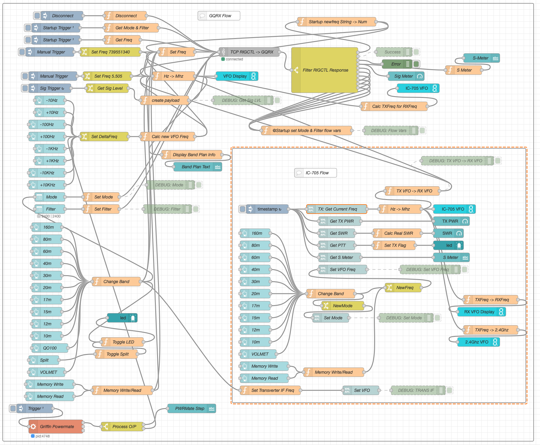
The Node Red flow is looking a little busier with the addition of split mode and the Griffin Powermate USB VFO which has really enhanced the useability of the solution. It’s very impressive what can be achieved with Node Red with a little imagination. You really don’t need to be a heavy weight programmer to make things work.
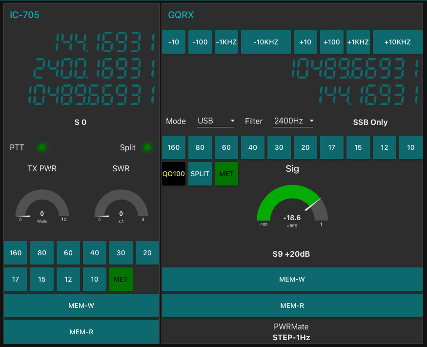
I also put together some code to calculate the S Meter reading from the dBFS data the GQRX SDR software generates. It’s not 100% accurate but, it’s close enough to be useful.
On the IC-705 side of the Dashboard I also now display the 2.4Ghz uplink frequency so that it’s available for logging.
So with the QO-100 Dashboard ready to go live I have now started putting together the 2.4Ghz transmit path of the ground station. I have the 2.4Ghz transverter and matching 12w amplifier from DXPatrol, the IceCone Helix 2.4Ghz antenna from Nolle Engineering, some LMR-400-UF and connectors from Barenco and an appropriate water proof enclosure from Screwfix to fit all the kit into however, I’m now being held up by one simple little SMA male to SMA male connector that I need to connect the transverter and amp together.
The SMA connector has been ordered but, is taking a month of Sundays to arrive! Hopefully it’ll arrive soon and I’ll finally get on the QO-100 satellite and start enjoying the fun.
More soon …