Many thanks to Sam (WN5C) who shares the following guest post: Notes from a homebrew POTA adventure Sam (WN5C) I recently wrote about the homebrew transceiver I built to operate on a month-long trip through the American Southwest. Upon arriving back in Oklahoma here’s the final outcome: 27 days, 40 parks, and 669 QSOs. I … Continue reading WN5C: Notes from a homebrew POTA adventure→
Thanks to Roy WN3F for alerting me to this. Tadashi-san has really built some beautiful stuff. Especially impressive to me is his use of the spectrum analyser and two-tone audio tests to look at IMD of the entire transceiver. See video above. FB OM.
Many thanks to Sam (WN5C) for sharing the following guest post: Homebrew in the Field by Sam (WN5C) What a week it’s been! I have the opportunity to spend a month traveling through and camping in the American Southwest (specifically, New Mexico, Arizona, and Colorado) doing archaeological work. And of course, that means the prospect … Continue reading Sam’s Thunderbird Mk 1 Takes Flight: A Homebrew Radio Field Report from the American Southwest→
Many thanks to SWLing Post contributor, Bill Meara who shares the following article from the excellent SolderSmoke Podcast blog: 2014 “Off the Shelf” Regen Comes Off the Shelf (Two Videos) Walter KA4KXX spotted an error in the schematic of my 2014 “Off the Shelf” regen receiver: The source resistor on the MPF-102 should be 2200 ohms, not 2.7 […]
Back in December, Becky Schoenfeld W1BXY, Editorial Director for ARRL’s On the Air magazine, asked me if I would be interested in writing a detailed set of step-by-step instructions for my Drive-on Portable Antenna Support. Naturally, I said I would.
I submitted my manuscript, along with an all-new set of pictures. The article was published in the current issue (May/June 2024) of On the Air (pages 20-22).
If you’re interested, have a look. ARRL members have access On the Air as part of their membership.
Ed W4YWA is far too modest -- he has built a very FB homewbrew transmitter. Congratulations Ed. I think your original plan to use a Web SDR receiver will work, if you and the other station are just willing to pause for an additional second or two to let the internet catch up with the real world. Also, you might find some Web SDRs that have less latency than other. You could used a little SW receiver or a simple buzzer for your sidetone ( I think sidetone is your most pressing latency concern.) My suggestion is to try to get a few contacts using the Web SDR (perhaps via schedule -- try the DX Summit or the SKCC web page to set some up). Then build yourself a simple Direct Conversion receiver to use with this rig. You don't have to try to build a VFO at 14 MHz (that can be difficult) -- you could build one at 7 MHz (use the circuit from our High School receiver project) and pair it up with a "Subharmonic Mixer" so that you can tune the 20 meter band. Please keep us posted on your progress.
Ed writes:
Home-Brew Fun and Failures
I’m not much of an amateur radio operator, but I enjoy the electronics, self leaning, and the home
brewing aspects of our hobby. Here’s an account of a recent effort.
While trying to re-learn CW, I discovered web-based SDR sites with waterfall displays, all kinds of
filtering and better performance than any of my vintage station receivers. So, I start thinking….. if I
had a little transmitter and a simple antenna, along with internet access, I’d have a capable station to
take on vacations to the beach. Yes I know, there are web based amateur radio stations, but
remember the operative words here are: “Home Brew.”
After pinging the Google machine, I came up with a two-stage 1-1/2 watt transmitter sometimes
refereed to as the “Universal QRP transmitter,” or the “Little Joe Transmitter.” There’s lots of
variations of this circuit but it is essentially a Colpits crystal oscillator coupled to a class-C PA.
I chose 20 meters because I didn’t want to hire an arborist to string my antenna. My design
modifications included a transistor switch that keys both the oscillator and PA, a VXO circuit,
power transistor protection, and a 5-th order Chebychev low pass filter.
Notice the (do I dare say, good looking?) enclosure. In a former life, it was a SD card reader from a
defunct PC. FYI, gutted CD/DVR drive cases also make fine enclosures for your home brew
projects.
I opted for a “foil side up – without holes” for my PCB design. All the parts are soldered down on
the lands - no PCB holes. I wanted to change parts without having to do open heart surgery.
Functional placement was also important to me. I took more time than I’d like to admit to organize
the circuit layout as I did, but I’m glad I did.
When all was said and done, it was time to power it up and….. and …. nothing! Not a single
function worked!
I won’t bore you with the debug stories that took forever, but the only part I didn’t have in my junk
box was the PA transistor. I got 10 of them for $5 off the Internets and they all failed to deliver. I
could only get a few tenths of a watt from my design. In a fit of desperation, I un-soldered a PA
transistor from an old CB radio and it immediately gave me 1.8 watts of pure CW ! ! ! !
Happy dance, happy dance!
But, save your accolades. There were lots of other problems; they were my problems not
component issues. For example, before you design your own RF filter be sure you understand cutoff
frequencies. They are not the same for every filter design. I suggest Paul Harden’s NA5N site to
learn about PA output filters. My first few filter attempts had the transmit frequency well down on
the attenuation curve. I was attenuating my own signal !
So, after weeks of “why don’t the damn thing work,” I got a clean signal. Whoo-Hoo!
Now it was time to unshackle the dummy load and see where I can be heard. And, Oh boy… I’m
beaming into Pennsylvania, Georgia and Northern VA, all from an inverted V on a tripod mounted
paint stick, held apart with two tent stakes.
But then, reality took over. My grandioso plans for using the web-based SDRs as a station receiver
(and the side tone oscillator for my transmitter) didn’t account for the latency delays of the SDR
software. If you ever listened talk radio and the host says, “Turn your radio off – the delay will
make you sound like a ….” you know what I’m talking about.
You would think that someone who over thinks everything, would have foreseen this issue before
spending countless hours of breathing solder fumes? Humility and eating crow are my better traits.
But not to worry, I’m not ready to give up. Stay tuned for more adventures of Home-Brew Fun and
Failures.
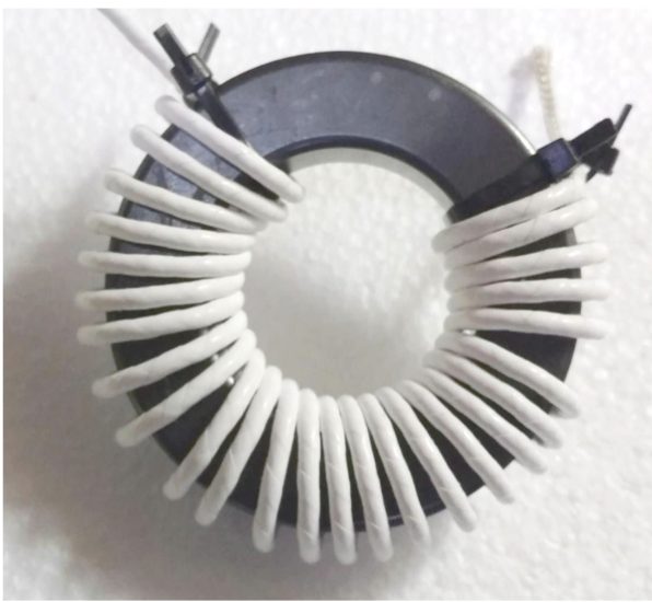
While I’m waiting for my QRPLabs’ QMX kit to arrive, I thought I’d try to learn something about toroid winding. This video takes toroid winding to a whole new level.
W2AEW on CW bandwidth
Question T8A11, in the Technician Class question pool asks, “What is the approximate bandwidth required to transmit a CW signal?” The correct answer is 150 Hz. The question says “approximate” because the bandwidth depends on the speed at which the Morse Code is being sent.
In this video, Alan, W2AEW, actually makes some measurements to determine the bandwidth of a CW signal.
KB6NU on LICW
A couple of weeks ago, Bob, K4LRC, asked me to speak to the LICW Portable Ops group about getting better at CW. I guess they ran out of qualified speakers. I don’t know if the group learned anything, but it was fun to speak to the group. TL;DR getting on the air and making contacts is the best way to improve your CW.
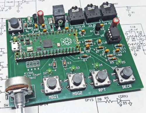
The PicoMite Keyer hardware has five pushbuttons and uses two I/O pins for the dit and dah paddle contacts.
One of the challenges that I faced when I started my Micropython keyer project was debouncing the switch closures. There are seven in all: five pushbuttons and the dit and dah inputs.
So, I did what everybody does nowadays—perform an internet search. I searched for “switch debouncing with Micropython” and got about a zillion references.
One of the first references is actually part of the Micropython documentation. The documentation suggests that one read the current value of a given pin, wait for the value to change, and then verify that the new value is stable for at least 20 ms. They give the following example code:
importpybdefwait_pin_change(pin):# wait for pin to change value# it needs to be stable for a continuous 20mscur_value=pin.value()active=0whileactive<20:ifpin.value()!=cur_value:active+=1else:active=0pyb.delay(1)
pyb, by the way, is a library of functions that support the PyBoard, a small microcontroller board that was designed specifically to run MicroPython. Pin is one of the classes in the pyb library that provides I/O pin functions.
More stuff from the internet
This is a simple solution, and really too simple for my project. So, I kept looking and found a bunch more solutions:
Jack Ganssle, a long time embedded systems consultant, has published a couple of pages on debouncing on his blog, A Guide to Debouncing, or, How to Debounce a Contact in Two Easy Pages. Being a hardware guy, Ganssle gives a nice explanation of the problem before he goes on to show us his solution.
Hack-a-Day has also tackled this issue with two posts, Embed with Elliot: Debounce Your Noisy Buttons, Part I and Part II.
What I ended up using is the asyncio library that was developed for MicroPython. This allows a programmer to implement a form of multi-tasking called “cooperative multi-tasking,” which is widely used in embedded systems. It’s more complicated programming this way—you have to keep in mind all the various things that can be running at the same time—but there are definite advantages as well.
For example, I think when I get to the point of implementing accepting commands via the USB port, it will be easier to do this. Commands will be arriving asynchronously, after all.
Another advantage to using this library is that it has drivers for switches, pushbuttons, ADCs, and incremental encoders. The switch drivers, for example, include functions that detect both short and long presses. This is a feature that I’m using in this project.
Hardware solution
There is also hardware solutions to debouncing switches. These range from simply soldering a capacitor across the switch to connecting the switch to a Schmitt trigger. For more information on these solutions, and how to make the tradeoff between hardware and software solutions, see Ultimate Guide to Switch Debounce by Max Maxfield.
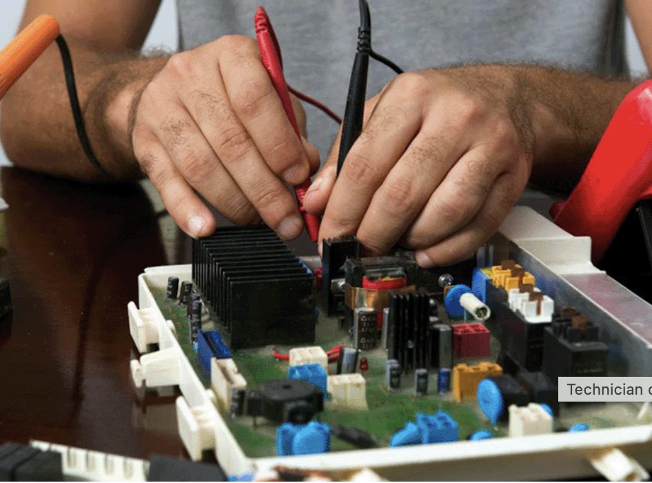
Jameco’s eight tips for debugging circuits include:
Understand the circuit.
Do a visual inspection.
Use the right tools.
Check power supply and ground connections.
Consider signal tracing and analysis.
Conduct incremental testing and isolation.
Learn from documentation and community resources
Develop a methodical approach
For a more complete description, visit the Jameco website. My advice would include a combination of #2 and #4. After doing a visual inspection, the first thing I do is to check all the cables and connectors. It’s been my experience that bad cables and connections account for approximately 80% of electronics problems.
This article by K9YC is chock-full of information about RF chokes for HF antenna systems, including circuit theory and practical construction techniques. The introduction reads:
Common mode chokes are added as series elements to a transmission line to kill common mode current. The line may be a short one carrying audio or control signals between a computer and a radio, video between a computer and a monitor, noisy power wiring, or feedlines for antennas. This application note focuses on the use of chokes on the feedlines of high power transmitting antennas to suppress received noise, to minimize RF in the shack (and a neighbor’s living room) and to minimize crosstalk between stations in multi-transmitter environments.
Bluetooth multi-path distortion
I’ve started using a set of Bluetooth ear pods to listen to podcasts on my Android phone when walking around town. (I do a lot of walking.) I’ve noticed that when I’m walking around downtown, sometimes the sound will go out in one or both ear pods.
At first, I thought that might be because my hand or my body was shielding the Bluetooth signal when my phone was in my pocket. Thinking more about it, though, I’ve decided that I’m losing the signal due to reflections from buildings as I walk by them. It’s multipath distortion!
I should have realized this right off the bat, as I’ve been teaching this very thing in my one-day Tech classes for at least the last ten years.
I kind of arrived at Dick Benson's QRZ.com page by accident, but what a happy accident it was. There is a lot of homebrew goodness on Dicks page, both SDR and HDR.
Last night, I worked Luis, EA1TG, and this morning, he sent me a link to a video on Twitch that he made of our contact. (Click on the image to go to Twitch. For some reason, I couldn’t embed the Twitch video here.)
This is kind of cool. I’ve been thinking of setting up my own Twitch channel to stream my contacts. I’m not sure if anyone would actually watch them, but who knows?
Bye-bye X-6100
Last summer, I purchased a Xiegu X-6100 from Radioddity when they put it on sale. I had a lot of fun using it. In some ways, it’s more fun to use than my Elecraft KX-3. I attribute that mainly to the brightly-colored waterfall display.
It’s just not the radio that the KX-3 is, however. For one thing, the KX-3’s antenna tuner is much better than the X-6100’s antenna tuner. The KX-3 tuner almost always achieves an SWR of 1.1:1 or less with my 66-ft. doublet antenna, while the Xiegu is satisfied once it hits 1.5:1. The color choices are also terrible, making it hard to read, especially in bright sunlight.
So, after making 36 contacts with it on my latest POTA activation, I sold the X-6100 last week. I hope that the new owner will have as much fun as did with it. And, find its shortcomings less annoying.
Bring on the toroids!
To replace the X-6100, I purchased a QRP Labs QMX kit. For less than $100, the QMX provides five band coverage (either 80m – 20m or 20m – 10m), CW and digital modes, an SDR receiver, a 24-bit 48 ksps USB sound card, CAT control, and synthesized VFO with TCXO reference. Since I’ll be using this for POTA, and propagation on the higher bands is headed in the right direction, I opted for the 20m – 10 version.
I also purchased the enclosure and power cord, so the price came to just short of $140, including shipping. Even so, that’s quite a deal, I think.
When I told my friends Rick and Paul about my purchase they jumped all over me about the toroids. One of them in particular has a trifilar winding and is supposed to be difficult to fabricate. I’m not a big fan of winding toroids, but I’m not scared of them either. Bring on the toroids!
In the meantime, I’ve been watching this video:
After watching it, it seems to me that the biggest thing to watch out for is how crowded everything is inside the radio. For example, there are several warnings about how close some of the components and traces are to one another. Forewarned is forearmed, though, so at least I’ll know what to look out for.
Stay tuned for reports on how I get along with the kit. Who knows? Maybe I’ll live-stream my toroid-building on my YouTube or Twitch channel.
Whenever I buy parts for a project, I always buy one or two extras. Over the years, I’ve amassed a sizable collection of random parts. Some of it will never be used, but sometimes my collection of parts has just what I need for something I want to build. I like when that happens.
A while back I wrote about an old homebrew coil I resurrected and paired with a 12-foot telescopic antenna. The coil, while effective, was built to use with a much shorter whip and is larger than what I need. I scoured my junk box and came up with most of the parts I needed to build a scaled-down version.
I should note that I built this coil specifically to use with my old MFJ-1956 12-foot telescopic whip. In this configuration, this coil covers 40M through 17M. So, if you have a different whip or want to cover different bands, you’ll need to modify the design accordingly.
Completed loading coil. Used with a 12-foot telescopic whip, it tunes from 40M through 17M.
I used the old coil as a guide to determine the number of turns I needed to cover the bands of interest, adding two turns for good measure. Using an online shortened vertical calculator, I figured I would need about 13.4μH to load the 12-foot whip on the 40M band. Using an online coil inductance calculator, I estimated the total inductance of my coil to be 14.8μH. So, it covers 40M with a turn or two to spare.
The new coil assembly measures 8.25 inches end-to-end, making it 2.25 inches shorter than the old coil. While it’s about 3.3 ounces lighter than the old coil, this new coil still weighs in at a hefty 10.8 ounces.
Parts List
With a few exceptions, my junk box provided the parts I needed to build the coil.
5-3/8 inches of 1.5 inch PVC pipe
(2) PVC end caps for 1.5 inch PVC pipe
(4) pieces of nylon grommet edging, 3.25 inches each. (The material I used has about 8 notches per inch)
16 gauge bare copper wire, approx. 12.5 feet
(1) 3/8-24 coupling nut, 1-1/8 inches long
(1) 3/8-24 x 1-1/4 inch stainless steel bolt (bottom mounting stud)
(1) 3/8-24 x 1 inch stainless steel bolt (top bolt)
3/8 inch flat washers & lock washers
(2) #10 x 3/4-inch self-tapping screws
Approx. 6 inches of RG-174 coax
Small alligator clip
Misc: ring lugs for ⅜-inch & #10 screws
Construction Notes
As shown in the accompanying photo, I drilled the end caps to accommodate the ⅜-24 bolts. The 1-1/4 inch bolt was used for the bottom of the coil, along with a flat washer and a lock washer. The 1-inch bolt was used for the top, along with flat washer, lock washer, and the coupling nut.
This is the coil form with the four strips of grommet edging glued on. The ends were drilled to accommodate the 3/8-24 bolts.
The coupling nut was one item I didn’t have in my junk box. My local hardware store is well-stocked, but they didn’t have them with the ⅜-24 thread. I eventually found what I needed on Amazon. It was a little pricey, but I didn’t have any better options at the time.
After cutting the PVC pipe to length, I temporarily installed the end caps. Then, I cut four pieces of the grommet edging to length and glued them on, using Goop® adhesive. Unfortunately, I can’t provide a part number and source for the edging. A local QRPer, Ron Polityka WB3AAL (SK), gave me several pieces many years ago. I’m pretty sure Panduit was the manufacturer. My stash was nearly depleted, but I had enough left for this project.
Before assembling the end caps, I made two short jumpers, each with a ⅜-inch ring lug on one end, and a smaller ring lug on the other. Then I tightened everything up. I left about a ½ inch of thread on the top bolt to go into the coupling nut. I was careful to ensure that my whip antenna would fully thread into the coupling nut.
Before winding the bare wire on the coil form, I installed a ring lug on one end. I drilled a pilot hole in the side of the lower end cap and used a self-tapping screw as a connection point. When you wind the wire on the coil form, try to get the turns as tight as you can. (I didn’t do as good a job winding the coil as I would have liked.) Once I finished winding the coil, I cut the wire to length and installed a ring lug. I used some more Goop adhesive on the grommet edging to hold the turns in place.
The last step was to build the clip lead. For this, I used a piece of RG-174 coax. There’s nothing magical about the RG-174; stranded hookup wire would be fine. I used RG-174 primarily because of its flexibility, plus the shield would be a good RF conductor. (The center conductor was unused.) I crimped and soldered a ring lug to the braid on one end, and soldered an alligator clip to the braid on the other end. Then I used another self-tapping screw on the top end cap to connect everything together.
On the Air
I wrote about my initial tests of the coil in a previous post. Using an antenna analyzer, I determined where to place the tap for each of the four bands. I then used a permanent marker to mark these locations on the coil, so I can quickly change bands without resorting to the antenna analyzer.
This is the completed loading coil installed on my truck for a POTA activation.
With the antenna mounted on my truck, the SWR is higher than I would like on 40M and 30M. This is not unlike other shortened, base-loaded verticals I’ve used in this configuration. An additional counterpoise wire or two might help. Also, grounding the bottom of the coil and feeding it a couple turns up from the bottom would provide a precise match on the lower bands. I’ve used that technique in the past. That configuration , however, is a bit more complicated to implement, given the way I plan to use this coil. So, I just use a tuner to keep the radio happy, and the antenna seems to work fine.
Wrap-up
My older, larger coil worked fine; so technically, this project was unnecessary. But, since I had most of the parts on hand, what the heck. It was a fun project, and I’m sure it will see a lot of use in the future.
We’re still alive! November and December have been very busy months. In that short time I both decided to find a new job, found a new job, and started the new job. I’m back into doing what I love best: Fixing things, and writing things. I guess you could just say I’m wired that way. …
I left you last having completed the installation of the vertical. I'm pleased to say, it's still up! And yes, I'm having a blast being back on the air. Here's what I've been up to.
After getting the vertical up, I set to putting the SB-200 back on the air as well. Last time I shared SB-200 stuff with you guys was when I just about killed myself by sticking my hand in the chassis with the HV power applied. I definitely learned my lesson and took many extra precautions this time around. Getting the SB-200 out of storage and converted back to 120v (no 240v in the new shack) I noticed the softkey circuit I had was not working, there was no keying action. The circuit was powered by a 3v lithium coin cell so its no surprise. I thought while I was in there, I'd rework the 12VDC power rectifier I built for the PC fans I put in there in our last blog post.
I decided to go full hog and just throw a 12v transformer, as well as cut out the case for better air flow. This turned out to work a lot better than the way I had it hooked up before and I didn't have to worry about the filament voltage from being impacted in any way. Unfortunately I did find out that you can't ground the DC side of the transformer to the case. It took a while to find out why the fan would stop when transmitting. In investigating all of that, I ended up going down to just 1 fan and I can definitely tell it works really well with just the one to keep the tubes cool.
Since I was running the amp on 120v I wondered if I could improve the performance with the lower source voltage. With the exception of the soft key and the fans, I'd made zero modifications or updates to the amp. Surprisingly the amp was totally untouched and working great all things considered. And yet, I had picked up replacement capacitors for the power supply when I bought the amp at Hamvention so I figured it was time to just replace the aged ones in the amp. You've probably seen pictures like the one below on the internet and I always thought, "oh that's a blown up cap," but it turns out that's just the glue that goes in the paper covers! All 6 of the caps in my amp, did end up being absolutely fine, but I did find a bad diode which I also replaced.
Everything else checked out and once it was all buttoned up everything looked great! I got the amp back on the air and it didn't take long until I reached the limit of the 15 amp circuit to the shack and that was about it. It became painfully obvious that I was just not going to be able to run an amp in the new shack without a more worthy circuit. And, do be honest, in all these years, I've not really enjoyed using the amp on CW. Friends will tell you, I'm a little extreme about having a quiet shack and once you get rid of the fan noise, the SB-200 is silent...until the T/R switch goes off. And man is it loud! I seriously considered adding QSK but it turns out there's no "drop in" boards available anymore so I kind of went off the deep end...
One of the greatest challenges for the typical Ham QTH is squeezing-in that low-band HF aerial for 160m or 80m. Loading coils, loops, creative routing of the wires around trees …
There are times when you wonder if your receiver and antenna are really working as they should. The band is dead, or empty, it’s the middle of the day, the D-Layer is sponging up every radio frequency excitation. Perhaps you can hear a few signals, but they are fleeting — and you need a steady and predictable signal source for a proper test. An RF signal generator will give you a steady carrier, but there are times when you’d prefer to have a true CW beacon to tune onto. This simple, general purpose multiband CW beacon can be run up on the frequency (or frequencies) of your choice, is powered on a 9V transistor radio battery, and can moved to attenuate to the desired signal level, for radio receiver system testing purposes.
This beacon transmits a hard-coded message in morse code on any frequency supported by the si5351 (10kHz to 160MHz). The code targets an Arduino Nano, Uno or bare ATMega328P and an si5351 breakout board. No display is necessary. You can add one, and controls, if you like. The code includes a simple CW keyer for manual sending (not used, but left in place for this application).
Any number of frequencies in the HF and VHF range can be specified by adding them to an array of transmit frequencies. The beacon iterates over the array and transmits the message on each frequency in sequence. The beacon’s CW speed is configurable. Sidetone is available as a 5v square wave on the D7 output. There is no support for switched low pass filters but this would be easy to add.
There’s a reason why most homebrew transceiver kits and scratch-built projects are monoband and single mode — theres a chance you’ll finish it, or at least, get it working for a while. Building a multiband HF transceiver is a big job, as any homebrewer who has attempted it will tell you. It may take years.
My build of Eamon EI9GQ’s transceiver is no exception. It was started in 2018, the first rush of enthusiasm resulting in a working superhet receiver on 160 to 40m, and boxed up in a custom solid aluminum case. This video shows it off circa 2018.
With a heap of work ahead, and a list of unresolved minor problems, other projects took priority, and the rig ended up spending the next four years in a carton (with all my notes, schematics, assembly and PCB sketches, and unused components). Until recently.
Schematics
It’s my normal practive to include kicad schematics, but in this case the EI9GQ designs are copyright RSGB. So go and buy Eamon’s book from the RSGB Bookshop, or on Amazon, you won’t be disappointed.
Resumption
E-mail discussions with another keen maker (Neville ZL2BNE) about his build of this transceiver gradually tickled my interest to resume. Nev was making good progress, had his rig transceiving, and was working QRP DX. I dug mine out of its carton and fired it up — it had all the appeal and problems that I remembered from 2018. I resolved to kick it along the road for a bit, to see how much interest I could reconstitute. Upon resuming, a number of issues needed addressing, some easy, some repetitive, some more difficult but not impossible. Here are those that I can remember…
Firstly, the 9MHz IF amplifier oscillated with the manual AGC turned up, and was generally unstable. To fix this, I put a 5k5 resistor in parallel with the drain tuned circuit — a well known technique for taming high gain stages. I figured that of the three identical 15 to 20dB gain stages, it made sense to damp down the gain of the first stage. This did the trick, and all three stages exhibited a nice resonance peak using the trimcaps, and overall stability.
Three stage IF amplifier module (EI9GQ).
The next thing was to calibrate the si5351, a simple job I’d never bothered to do, resulting in the display showing odd and fractional frequencies for the property resolved SSB stations in the 2018 video. If you want to know how this is done, go to your si5351 library’s README file, it is quite easy to do, and once done, lasts for years, or for ever.
Next problem was the LCD backlight. The large font 20×4 LCD I had chosen for this rig was a bit of a novelty back in 2018. I liked that it’s huge characters could be read from half a room away. I used to joke with myself that I’d still be using this rig in my 90s, when all the compact rigs with fiddly little OLED displays were beyond my failing eyesight. And the four lines of 20 characters gave me extra display space for luxuries like a UTC clock and metering. But that big display had an equally oversized backlight which could light up a darkened room, but drew more than half an amp. Although this rig was intended for the shack bench, I was not used to my receivers pulling over an amp.
I decided to multiplex the LED array with a simple PWM LED dimmer, which uses one half of a 4093 quad gate as a variable duty cycle oscillator running at around 70kHz, driving an IRF540 FET switch. This worked a treat and the dim potentiometer was mounted right on the front panel. It controls the backlight from off to 90% on, when it drawn around 500mA.
LED (backlight) dimmer module.
The next mini-project was an AM detector. I was not interested in full AM transceive capability– I have other homebrew projects for operating VK legal limit AM — but I did want to be able to enjoy decent AM reception using the high quality 6kHz filter in this receiver’s set of three KVG crystal filters. I chose an infinite impedance AM detector, successfully used in a prior AM receiver project.
AM detector and CD4046 audio routing switch.
This mod necessitated making a PCB to overlay the existing product detector and audio preamp, with a plug-in board containing the AM detector, it’s own preamp, a miniature relay to steer the incoming IF signal to either detector, and a shared 4046 quad bilateral analogue switch which selects the product or AM detector’ s output, and additionally does receiver muting and Sidetone routing when in CW transmit mode. This assembly worked well. One hickup — I originally left the BFO powered up in AM mode — and even though there was no direct BFO coupling anywhere, there was more than enough stray coupling to resolve sideband. This was fixed by switching the BFO board’s DC power off in AM mode.
The next task involved coming up with a mechanism to select one of the three KVG (ex TelRad) filters. These high quality 9MHz crystal filters were common on eBay a few years back, and are a feature of this receiver. These filters came in a set of three. In a slight departure from superhet convention, a separate filter is used for USB and LSB, with a 6kHz AM filter in the middle. The BFO runs permanently on 9Mhz. I wanted to have filter selection under software control, so that the correct sideband filter would be selected for the current band. One of the front panel pushbuttons was used for a mode control — pushing it cycles thru the sidebands and an AM setting. A small daughter board was added to the filter assembly containing a PCF8574 demux IC on the I2C bus. A few additional lines of code implemented a simple control function.
9MHz IF crystal filter selector (PCF8574 on vertical daughter board).
The 2018 receiver’s front end board included space fo r an RF amp block, with a pair of miniature relays to bypass it. The original PCB was layed out for a MMIC which probably would have worked fine but in the end I built up one of EI9GQs broadband RF gain blocks using a parallel pair of MPSH10 transistors for around 20dB of gain. The EI9GQ amp was built on an overlay board sized for the available space.
A few minor additions followed. A 41MHz Low Pass Filter was added on the VFO buffer input. On the highest band (28MHz) the VFO is 9MHz higher, on 37MHz. This low pass filter cleans up any VFO harmonics, probably low anyway, but a safety precaution.
40MHz LPF on input of VFO buffer.
The diplexor was added, a balanced tee arrangement, with series and parallel 9MHz tuned circuits arranged to pass through 9MHz energy, but sink all other frequencies into 50 ohm resistors. This ensures proper termination of the receiver mixer and keeps unwanted mixing products, particularly at the image frequency, out of the first IF amplifier.
9MHz diplexor (yellow toroids), handmade DBM receiver mixer to right.
One of the nore repetitive jobs (which just has to be done!) is making and tuning up the remaining Band Pass Filter modules. Three mire were built, for 17, 15 and 10m, using the EI9GQ design. This gave eight bands, 160, 80, 40, 30, 20, 17, 15 and 10m. My approach to the last three boards was mostly as I’d used in 2018, other than improving the use of right angle 0.1″ header pins inserted through a row of holes drilled through the PCB for mechanical strength.
Next job was a small board mounted on the rear panel next to the two SO239 sockets. This board has the transmit-receive relay, and a second relay that switches between two SO239 for an Antenna A/B switch. Three 7812 regulators supply the three supply rails, 12v always on, 12v receive, 12v transmit. All three unregulated DC supplies are available on headers as well, to avoid heavy current being drawn thru these regulators, such as the transmitter PA and the LCD backlight.
T/R relay, antenna selector and 12v regulator PCB (relays underneath).
The rear panel has two antenna sockets (for A and B antennas, switched from the front panel), a panel XT60 socket for DC 12V, and a set of 3.5mm and RCA sockets for connections (external muting, paddle, external speaker, and an auxiliary RCA, as yet unassigned). These 3.5mm switched stereo sockets are very useful pieces but unfortunately are not long enough to go through a 3mm aluminum panel. The best solution is to mill out a recess larger than the socket, but that requires a milling machine that I don’t have. So the workaround was to cut a rectangular hole in the 3mm rear panel, and bolt on a 1.2mm aluminum plate to hold the sockets. Its easy to paint and label this small piece.
Rear panel.Small PCB for the 3.5mm sockets, with connectors (3.5mm sockets underneath).
Preview of the Exciter
To turn the EI9GQ receiver into a transceiver I needed a microphone amplifier, balanced modulator, transmit mixer, T/R switching, a PA stage and LPF set. Back in 2018 I built Eamon’s LM324-based microphone amplifier (a design out of EMRFD) and another hand made diode balanced modulator. All of these mixers use 1N5711 Shottky diodes individually matched to within a millivolt on the diode test setting on my digital multimeter. The transmit mixer is another hand made diode ring mixer, this time an unconventional triple balanced mixer.
Microphone amp (with header for a compressor), balanced modulator, transmitter triple balanced modulator. Vertical dividers will host MPSH10 gain stages before and after transmit mixer.View of component side of the last gain stage, 2xMPSH10s.
The PA chain after the transmit mixer will be MPSH10 x 2, 2N5109 and a pair of RD16HHF1s for about 10 watts 160 to 10 meters. The LPFs will be by Eamon, derived from the original W3NQN designs, each filter on its own plug-in board, relay-switched at either end, filter selection via another PCF8574 on the I2C bus. There will be six LPFs (for 160, 80, 40 and 30, 20 and 17, 15 and 10 meters).
What’s next?
If you’ve made it this far, thanks for reading, feel free to leave a comment, and stand by for the third and final post on this transceiver project, which will address completing and commissioning the SSB and CW transmitter stages.
Weak Signal Propagation Reporter is a global radio propagation monitoring and reporting network comprised of thousands of low power beacons operating on the amateur radio bands. WSPR beacons can be detected from the lowest of Medium Wave frequencies (137kHz) all the way through the HF spectrum (all the bands from 160m to 10m are popular) to the VHF bands, 50 and 144MHz. WSPR receivers decode the tiny beacon packets and upload them to a central database, at WSPRNet.org, where anyone can literally ‘see’ the propagation paths that are currently open.
Equally, you can go back and revisit the radio frequency propagation conditions during any previous time window. Running a WSPR beacon from your home allows you to ‘watch’ the propagation paths open, peak, and close each day under the influences of solar radiation, sunspots, and other ionospheric conditions. Arduinos and a few common accessory boards that can be had for tens of dollars make a beacon accessible to just about any experimenter (with an amateur radio license).
WSPR beacon in an Arduino Uno prototype case.
I’m late to the WSPR party. I’ve wanted to try a beacon project for a few years. A while back, I took a copy of the ZachTeck script and experimented with it and a Ublox GPS, but after getting the NMEA strings decoded from the GPS unit at roughly one second intervals, the rest of my code was over-engineered and bloated, and did not fit into the small memory constraints of the Arduino Nano. I put is aside.
Recently, I did a much needed upgrade to my Arduino IDE and libraries. The thought occurred to me that improvements to both IDE and libraries may give me a fighting chance of getting that old WSPR script fitting. When I opened it up, and started to work through it, I saw some obvious ways of reducing memory usage. I had too many String objects (memory-hungry). And my code was writrten to parse each NMEA message string and tokenise it. This allowed me to get to discrete data fields a long way down the messages, like the number of detected satellites. In a simple WSPR beacon, all you really need is the UTC timestamp at the very start of a number of the NMEA messages. I ditched the superfluous stuff and got it uploading, and more to the point, not hanging!
WSPR dataset applications
WSPR is brilliant for teaching you about rare and exotic places that you feel compelled to Google when they turn up on your map in the morning, places like Orlygshafnarvegur (TF4AH, Iceland) or Fuerteventura (EA8BFK on the Canary Islands).
The database of historical propagation across the HF spectrum is widely used by amateur researchers to learn about propagation and has some more serious applications as well. Experimenters have used the data to support ideas or research questions about how symmetrical propagation is at opposite sides of the globe in the same period, and to test antennas. More seriously, a theory was proposed that impressions in the WSPR dataset may indicate the path of the lost flight, Malaysian Airlines flight MH370.
The schematic is so simple it really doesn’t need a kicad. The Ublox 6M GPS connects to Arduino D2 and D3 for serial data transfer. It also needs GND and +5V. The si5351 breakout board uses I2C and so goes to Arduino A4 (SDA) and A5 (SCK). Connect the si5351’s CLK0 to whatever low power HF amp you like. Mine is from Experimental Methods in RF Design (EMRFD), Fig 12.32, but I could have chosen any number of similar two-transistor stages.
WSPR works on truly tiny power levels. If you connect the bare si5351 clock output to an antenna, you will get decodes! (You should add a Low Pass Filter if this is anything more than a quick test). So use a single 2N3904, or anything with gain, up to a full 5 watt QRP PA with an IRF510 or Mitsubishi RF FET, which is a ‘big gun’ in the WSPR world. Mine uses a 2N3904 and 2N4427 in common emitter feedback configuration, delivering around 10 volts peak to peak into 50 ohms, followed by a W3NQN Low Pass Filter for the band of interest.
200mW QRP PA.
Gallery
20 meter European WSPR decodes from the beacon in Melbourne Australia. 12,000 miles on 200milliWatts! More European decodes, and a spot from Auld Blighty! And a decode in the USA in the same timeslot, about an hour before sunset.
Acknowledgements
Thanks to Harry from ZachTek for making his code open source. And to Jason Milldrum NT7s for his si5351 and JTEncode libraries.
SPRAT #192
After publication of this project in the RSGBs SPRAT #192 Autumn 2022 a number of builders commented below the post or contacted me with build reports and questions.
First, the 12v DC series decoupling resistor was not labeled in the published schematic, it can be anything between 47 and 100 ohms (see corrected scheatic below).
Schematic errata.
Secondly, Ian McCrum did an LTSpice model of the PA which revealed that I omitted a resistor from the original design in EMRFD (in parallel with the 100n coupling capacitor between the stages) which forms part of the biasing of the PA transistor. If omitted, the PA works, but with reduced power. Adding the resistor increases the RF power output to around 0.5W, although this will vary depending on drive level, the PA transistor, and the DC supply voltage. Thanks Ian for taking the time to LTSpice this QRP PA.
Steve K8SDK got more power out of his PA by increasing the si5351 drive level from 2MA (my value) to 4, 6 or 8MA. There is a general understanding and some analyses that report the si5351 clock phase noise gets dirtier as you go up in drive level, and for this reason I left it at 2MA. But with sub 1 watt power levels and a LPF on the output I don’t think it would make any practical difference.
On the question of WSPR beacon power, I don’t think 0.5W is preferable to 0.2W under curent band conditions. With 0.2W the decodes at DX WSPR receivers get marginal and the spread of the band opening can be seen as the grey line moves across the globe. Higher beacon powers can result in saturation which looks like a more rapid ‘lighting-up’ of the remote receivers on the map, and the subtleties of propagation can be lost. This is another way of saying that you should really use a minimum power necessary to get decodes at the far end. However my preference for low power is a personal preference, and some may need slightly higher power to overcome antenna losses.
Several people reporting having to use the set_correction() call with the second parameter (around line 320). I added a comment note immediately above the call in question:
// NOTE: There was a library change to the signature of this method. If you get a compiler error, try this: // si5351.set_correction(19100, SI5351_PLL_INPUT_XO);
I did it this way to allow for compatibility with subsequent versions of the NT7S si5351 library. But a few people got the compile error and did not trace it back to the offending source line, or perhaps read the comment. I should have just made this change in the repo code to make it foolproof for all comers.
Neil G0ORG emailed with a question about si5351 calibration, his calibration attempt resulted in a value of 149850 for the call to set_correction(). I personally have not seen a calibration offset that large, however, the tiny crystals on the Adafuit and clone breakout boards must vary considerably. Neil reported that this offset pulled his si5351 outside the WSPR passband — we are not sure what went wrong with the usual calibration process for this to happen, bit Neil got his beacon back on the spot by experimentally reducing this large offset value.
Stephen G3ZNG had problems compiling the sketch, and after a bit of investigation discovered he had a previously installed JTEncode library. Upgrading the library fixed the problems and Stephen reported his beacon was working.
Chris G4BMW had the same problem. When he installed JTEncode v1.3.1 and Si5352 v2.1.4 it worked. Chris then discovered that GPS units do not always work inside, and had to move his unit next to a window to give the GPS receiver a sniff of the overhead statellite’s signals.
John G8CHP emailed me a photo of his completed WSPR beacon in a sandwich box. John reports spots in western Canada from his QTH on the east coast of the UK. John used a QRP Labs QLG1 GPS unit, mainly because it was on hand, and a 2N3866 for the PA.
Jonathan G5LUX got his beacon working on a breadboard, and it worked first time.
Aaron K5ATG emailed to discuss his build options, saying that most commercial WSPR beacon products are reasonably pricey for what they are, and my design is made from just a handful of commonly available components, most of which he already had.
Nigel, G4ZA emailed me to say that he had also come up with his own homebrew WSPR beacon, and that Harry’s code (Zachtek) saved him a ton of work too.
Steve K8SDK used three FETs (presumably in the conventional Class E PA configuration as used in many QRP CW PAs) (see comments below post).
And finally, Dave AA7EE has done a superlative job of building his own WSPR beacon using my script, and of course, his blog write-up is amusing, informative and a celebration of the finest amateur radio homebrew spirit. Dave set up his beacon on 10m but had si5351 stability issues which he describes in detail. He solved the drift problems with patience and experimentation, eventually settling on 20m. His post shows remarkable QRPp WSPR results. Thanks Dave for the acknowledgments peppered throughout your post. (See also Dave’s comments below).
A number of builders commented below the post, please read for further discussion. As well, I did receive other emails so if I have missed you please leave a comment below.
Beautiful and thoroughly photographed and documented build by Dave AA7EE.