Discover the latest in ham radio technology with the Xiegu X6200, featuring RF direct sampling, versatile frequency support, and built-in wireless capabilities. Explore key features, setup tips, and recommended accessories in our comprehensive overview.
Figure 1: The RX-888 with external clock input (right) The enable/disable switch is barely visible behind the USB connector. Click on the image for a larger version.
Note: I have posted blog two previous entries related to the RX-888 (Mk2) that you may find relevant:
Measuring signal dynamics of the RX-888 (Mk2) - link - This is a discussion of how much (and little) signal is needed to stay within the dynamic range of the RX-888 and the effects of gain and attenuator settings.
Adding an external clock connection
While the internal 27 MHz TCXO in the RX-888 (Mk2) is pretty good, there may be instances where one wishes better accuracy and stability. Fortunately, the RX-888 (Mk2) has provisions for doing so in the form of a jumper to disable the internal clock (when the jumper is removed) and a small connector (a tiny U.Fl) on board to accept that clock.
Unfortunately, it is up to the user to add the cable to feed an external clock - but short 4-6" (10-15cm) cables already fitted with a U.Fl male and SMA chassis-mount female connector are easily obtained from the likes of Amazon, EvilBay and others - just be sure that you do NOT get a "Reverse" (RP) SMA by mistake!
This leaves the jumper. While many people simply remove the jumper and mount the external clock connector between the HF and VHF inputs - or sometimes to the right of the USB connector knowing - from then on - their RX-888 will be unusable unless there is an external clock input - I prefer to make use of the ability of the internal clock to be switched - using (ahem) a switch allowing for testing/use of the RX-888 in a "stand alone" configuration - but this is up to you.
If one is careful, it's possible to mount the external clock SMA connector and switch on the same panel as the USB connector, orienting so that its handle is toward the "Clock In" connector to indicate that an external clock is to be used - but labels or markings are always nice, too!
If one takes the route of mounting the external clock input between the HF and UHF inputs, the switch could be placed to the right of the USB connector - or, if as in the case of one of my RX-888s where I put a heat sink on the FX3 chip and there wasn't room there - I found a very small toggle switch that just fit between the case screw and left side of the USB connector and tip of this switch may be spotted just behind the USB connector in Figure 1, above.
IMPORTANT: As the external clock input is simply wired in parallel with the internal 27 MHz clock. What this means is that with the internal clock enabled, it will be present on the external clock input. Similarly, if you supply a 27 MHz external clock without disabling the internal one, the two will "fight" each other and you'll get "garbage" results.
What type of signal to use as an external clock
The best external clock source is a 27 MHz sine wave of between 1.25 and 3.3 volts peak-to-peak.
A series coupling capacitance of between 100pF and 1000pF (470pF typ.)should be present on the "center pin" between the RX-888 to eliminate a DC path to ground on the signal line.
While a capacitively-coupled 27 MHz sine wave is recommended for reasons that will be mentioned later, a lot of devices offer square wave outputs - and getting these to work reliablyrequires at least a little bit of attention.
Using the Leo Bodnar Precision GPS Clock to drive an RX-888:
Because the RX-888 natively requires a 27 MHz clock this means that if you already have a 10 MHz standard (GPS, Rubidium, etc.) kicking around, you will not be able to use it directly. While it's not too difficult to synthesize 27 MHz from 10 MHz (a number of Si5351-based devices can do this) it's most common for users of the RX-888 to use a device such as that sold by Leo Bodnar, which can be programmed for almost any frequency (from audio through UHF) with good precision and accuracy.
You can look at these products here: https://www.leobodnar.com(I have no stake in Bodnar, but I have used them and I and others have had good success.)
The most commonly-used device is the Bodnar "Mini" - which has one output - and this single output is often "daisy-chained" between RX-888s. There is also the functionally similar LB-1420 with a single output and the "Precision GPS Reference Clock" which has two signal outputs - but there is very limited ability to set the "second" output to a specific frequency and it's mostly useful for outputting the same frequency on the two ports - or outputting a 1PPS signals on the "unused" port.
As the RX-888 (Mk2) external clock input is directly coupled to its Si5351 clock synthesizer, we have to act as if we are driving that chip directly. While not directly specified in the Si5351 data sheets (at least the ones that I have found) testing done my myself indicates that a capacitively-coupled sine
of about 750 millivolts peak-peak will trigger the '5351 reliably: A
bit of looking in online forums reveals the consensus that a 1 volt
peak-peak sine wave is suggested so I would be comfortable with the
suggestion of this amplitude being used a a guideline.
Testing with a square
wave - such as that produced by the Leo Bodnar GPS reference revealed
that the drive level was far more finicky - and this has to do with the
fact that a "square" wave with a reasonably fast rise time does NOT
remain a square wave for very long as it quickly turns into something
rather spiky and distorted as depicted in the image below:
Figure 2: A typical square wave output from a Bodnar GPS reference at the end of about 3 feet (1 meter) of unterminated cable. Ringing is evident!
This
27 MHz signal shows clear evidence of ringing: This was measured right
at the RX-888 with the signal passing through around 3 feet (1 meter)
of 50 ohm coaxial cable. As the '888 does not offer resistive
termination, it presents a simple capacitance at the end of the cable
and this tends to distort harmonic-rich waveforms like a square wave.
With
multiple "spikes" that can occur on such waveforms due to distortion,
it's possible - even likely - that certain combinations can result in
multiple triggering peaks of the waveform. In an extreme case, such
distortion can cause the Si5351 to be triggered at twice the
actual clock rate - but rather the result may be instability resulting
in the RX-888 clocking which can be manifest as anything from no signals
being "present" to those that are being off-frequency, varying, or just
"noisy" - and this errant behavior may vary with temperature and slight changes in operating voltage.
It's important to realize that like the RX-888, the Bodnar is ALSO DC-coupled which explains why the above waveform in Figure 2 largely rests above the center line (zero volts) with the exception of some "ringing" which extends negative and is likely being clamped somewhat by the '888's internal diodes.
With
a 3.3 volt waveform emanating from the Bodnar, we can reasonably expect
that - if the signal isn't too "ringy" that a signal exceeding about 1
volt positive just once per cycle is likely to trigger the 888's Si-5351 correctly.
IMPORTANT: If you try to directly drive an RX-888 with the output of a Bodnar, it will probably NOT work reliably! I have observed this with my own Bodnar/RX-888s and many others have reported the same issue.
Remembering that the external clock input of the '888 goes directlyto
very sensitive logic devices, a simple resistive attenuator pad will do double
duty:
Rather than a very high impedance circuit that has a low
resistance path from the outside world to a sensitive logic gate,
resistance to ground offers a degree of protection by offering a
relatively low resistance to ground and the series resistance provides
at least some limit to input currents.
While theoretically OK, the output of the Bodnar will not reliably drive the input of the Si5351 in the RX-888 directly, but being reduced to half or third of its original output seems to be pretty reliable and is less likely to cause clipping of diodes on the input circuit which can exacerbate ringing and other types of waveform distortion.
A
6 to 12 dB resistive pad - either 50 or 75 ohms - is a reasonable choice offering a bit of voltage
reduction - but staying well above the 1 volt usability threshold - and
such a pad, even if it is not connected to a 50 ohm load, will provide a
bit of resistive termination, likely reducing the tenacity of
reflections. While a resistive pad does not offer DC decoupling between the center pin of the '888's external clock input, it works with the Bodnar as that device sources a square wave referenced to zero volts so the pad simply acts as a voltage divider for that square wave.
Testing has shown that the '888 seems a bit more forgiving of signal drive levels if there is a DC blocking capacitor on its signal input - something that could be provided by placing a "DC block" device (available in SMA, BNC or F-type connectors)between the '888 and the external clock source.
Caveats and warnings - and why the '888 is so finicky about its external clock
The external clock input of the RX-888 - as described in better detail in the next section of this blog post - is connected DIRECTLY to inputs within the '888 and as such, it has a few undesirable properties:
There is a DC connection between the external clock, the oscillator output and the input to the 888's internal Si5351 synthesizer. This exposes the clock input directly to extremely static and voltage-sensitive inputs.
Because of this, it's very easy to damage the RX-888 when using and external clock, particularly if there are voltage potentials between different pieces of equipment.
There is diode clamping between ground and the 3.3 volt input. In the '888, this is primarily a BAT99 dual diode, but it also includes the protection diodes of the other devices in the circuit - namely the output of the onboard 27 MHz oscillator and the input of the Si5351 itself. At first this might seem like a good thing - and it sort of is - but this means that any signal input to the RX-888 should be capacitively coupled - or directly to a 0-3.3 volt signal. This is one aspect of the '888 that was definitely not well considered or implemented.
What this means is that if you try to drive the RX-888's clock input with a source that is DC "grounded" - which includes devices that are transformer-coupled (e.g. a splitter to send the clock to multiple units) that the voltage output will be bipolar.
For example:
If you were try to use a T1-1 isolation transformer to break a ground loop between the external clock input and the Bodnar - as well as other devices - the signal input may be 3.3 volts - but bipolar - that is, it will go above and below "ground" by about 1.65 volts - but since there is diode clamping, the negative-going signal will distort the waveform.
The result of this can either be finessing required to find the precise drive level to make it work at all or - sometimes - you will find the signals at the wrong frequencies (sometimes at about half the expected frequencies) if the badly-distorted waveform triggers the input of the Si5351 synthesizer in the '888 twice on every clock cycle.
All of these factors often confound users of the RX-888 (Mk2) trying to feed an external clock - and things get more complicated if multiple devices are use. For example:
As with any sensitive piece of RF equipment, having multiple, disparate connections between pieces of equipment will usually end up with circulating currents - and since every conductor has resistance, this can cause noises to appear in the RF input. A few examples:
The RX-888 - or any SDR - will have multiple connections to it - typically the antenna and power input. In the case of the RX-888 and many other SDRs, this means an antenna and USB connection.
Isolating the RF signal lines from longitudinal currents (e.g. common mode) is a useful tool.
Often, this can take the form of small coaxial cable (RG-142 or RG-174) wound with 8-12 turns on an FT-140 or FT-240 core of 31 or 43 material (the former being better for lower frequencies). This is useful for HF (160-10 meters) but it loses efficacy below this and is not helpful if your interest extends into the AM broadcast bands and lower frequencies (e.g. longwave - including LF and VLF which includes the 2200 and 630 meter amateur bands.)
Another tool can be an "voltage balun" - essentially an isolation transformer with no DC connection at all. Often, these are built around the Mini-Circuits T1-1. These lose their efficacy below a MHz or so so they may have excessive attenuation on LF and VLF frequencies. At higher frequencies (above 10 MHz) their common-mode rejection also starts to drop meaning that in a very noisy environment, signals can "leak in" at high HF from the surrounding equipment - something that needs to be checked if you try it.
Power supplies and computers (via a USB cable) are notoriously noisy, so you WILL get circulating currents flowing between the devices. Having a choking USB cable (e.g. 6-12 turns on an FT-140 or FT-240 core of 31 or 43 material) can help significantly, as can doing similar on a DC supply line and also choosing a "known RF-quiet" power supply.
Adding a "third" connection to the receiver - such as the external clock, in case of the RX-888 (Mk2) - can further complicate issues as it adds yet another avenue of common-mode currents and noise.
This connection, too, should be appropriately isolated - but doing so is complicated by the way the external clock input is implemented.
The fact that the external clock device is connected to a potentially-noisy power supply and a GPS antenna - which may or may not have its own grounding (which can further introduce circulating currents) is yet another thing about which you should be wary!
One issue that also arises is that output of devices like the Bodnar are square wave. This, by itself, isn't a problem - and a direct connection between the Bodnar and '888 - since they both have 3.3 volt signal levels - works OK, at least with very short cables when using a 6-12 dB pad.
Conveying this square wave signal - particularly over greater distances and considering that the clock input to the RX-888 is high-impedance with a bit of capacitance means that long runs (anywhere near 1/4 wave at the clock frequency or longer) can result in reflections due to unterminated cables. What one can do is put a 50-75 ohm termination at the far end of the cable. This, however, does not help with the issue of DC/galvanic isolation between individual receivers.
Testing the stability of your external clock mechanism:
As properties of solid-state devices change over temperature - and signal levels may vary depending on what other devices are connected to your clock source - it would be a very good idea to varying the clock signal to determine if you have enough margin to allow it to work if levels change, or if you are on the "ragged edge".
Reducing the signal level is the most obvious test: The use of a step attenuator - or use a variety of fixed attenuator pads (be sure that they pass DC) and reducing the level by between 1 and 15 dB - and then observing when clocking becomes unreliable: This will give you a good idea as to the margin between what you are feeding to the '888 and when it will quite - and it may prompt you to reduce your signal level slightly.
Using HDSDR under Windows
Determining when the clocking signal into the '888 becomes unreliable is a bit trickier in some cases. By far the easiest is to use a program like HDSDR with the "SDDC" ExtIO driver on a fairly fast Windows computer with USB3 ports: A higher-end Intel i5 or medium-high end Intel i7 will suffice. Connecting the '888 to an external antenna and tuning in a reliable signal (like a shortwave broadcaster or a time station like WWV/H or CHU - or tuning it your own signal generator) while watching the waterfall will tell you immediately when the external clocking fails.
If you are using Linux with ka9q-radio, you can use the "Monitor" program to tune a signal with the audio being sent to the default audio device - but doing this is beyond the scope of the document. If you are using a Mac, I don't have a suggestion unless someone speaks up.
Transformer-based signal isolation NOT recommended for the '888's clock input - sort of...
It is important for any receiver to minimize the amount of current circulating through the "ground" connections. Such currents in an analog receiver can induce hum in unbalanced audio lines and if the receiver is actually a transceiver, those same signal paths can induce RF into seemingly unrelated equipment in the ham shack.
Sometimes overlooked is the fact that these same currents can induce RF currents on the cables interconnecting equipment and it is likely that these will find their way into the receiver's front end and degrade performance by raising the noise floor. This is especially true when a computer-connect software-defined radio - like the RX-888 - is involved as we now have a connection (via the USB cable) to a device that is likely to be "noisy" at RF - namely the computer - but this also means that noise can come from other devices to which this computer is connected directly or indirectly, namely its power supply, other peripherals, its power supply - and noisy devices on the AC mains into which this power supply is plugged.
Current "balun"
For receiver RF connections one way to deal with this is to use a common-mode RF choke which is typically a dozen or so turns of coaxial cable wound on a T-140 or T-240 toroid - usually with 31 or 43 type material. This will break up common-mode currents on the cable - at least at HF - and can reduce such issues and this works for both the signal (antenna) and external clocking lines.
At DC and mains frequencies such chokes offer little/no efficacy and at low frequencies (below a MHz or so) these chokes lose their effective series resistance owing to limited inductance. What this means is that if you have strong circulating currents (e.g. current flowing between your antenna "ground" and house mains "ground") they will have little effect.
Voltage "balun"
A possible alternative is to use a transformer to couple between RF sources: A reliable, low-cost, commonly-available device for this is the Mini-Circuits Labs T1-1 which provides complete galvanic isolation between the source and load with a reasonable degree of longitudinal isolation.
While the T1-1 works well for the RF input, it will not work so well for the RX-888's external clock input by itself and the reason for this is that the output from a transformer winding is, by definition, bipolar about the zero volt point. In the case of an external clock signal of, say, 1 volt peak-peak, each half would be above and below zero volts and with a direct DC connection to the Si5351's input it is unlikely to properly drive/trigger it.
If the signal is of higher amplitude - such as our 3.3 volt square wave - half of this "ugly" waveform will lie below ground potential and that below the 0.6 volt diode conduction voltage will be clamped, potentially distorting the waveform even more.
If a transformer-based method of isolation is used it is strongly suggested that a capacitor be placed in series with the '888's signal input to allow the waveform and voltage to float above ground and avoid negative clamping. As mentioned earlier, a "DC Block" device could be used if you choose not to build your own device.
Example homebrew devices:
Here are a few (relatively) simple devices that one could build on a piece of scrap PC board - or you could go through the effort of designing and building a board with these features.
Figure 3, below, shows a simple resistive coupler incorporating the features suggested above:
Figure 3: A simple 10-ish dB resistive pad with DC blocking to keep the external clock input of the RX-888 "happy" and to prevent clipping of negative-going voltage by built-in protection diodes. The "small" capacitor value also minimized the amount of stored charge dumped into the '888 due handling/shorting of the input cable.
This diagram shows a resistive pad that offers about 10 dB of attenuation - the values being determined assuming a 50 ohm system - but since the '888's input impedance is almost exclusively capacitive (a few 10s of pF) it is operating more as a voltage divider presenting a resistive load that just happens to be around 50 ohms. The coupling capacitor between the pad and the '888 offers DC blocking to make it more forgiving to varying signal levels. While the capacitor blocks DC, the signal being input to the Si5351 will find its own level due to the clamping effects of the protection diodes in the '888.
Also shown is the optional inclusion of a 1000pF capacitor that can be inserted at point "X": This will decouple DC and mains AC currents that might flow between the clock source and the RX-888 itself - but it is low enough impedancethat it does not necessarily offer RF decoupling between devices. With the circuit shown above, however, you can precede it with decoupling device - such as a common-mode choke (e.g. current balun - the type with a dozen or so turns on a toroid) or even a T1-1 transformer.
Figure 4, below, shows another possible approach:
Figure 4: This circuit provides both common-mode isolation and a degree of band-pass filtering of the 27 MHz clock signal: Filtering to a sine-like waveform reduces glitching due to cabling issues (reflections, misterminations) as well as offers a degree of protection to the RX-888's input as the filter will limit the amount of energy that could be imparted. It also provides a (small) degree of termination (<150 ohms). The "optional" 1000pF capacitor shunts low level leakage of the 27 MHz signal due to transformer imbalance - but it is suggested that one use a common-mode choke to restore isolation at HF frequencies.
This device is slightly more complicated, but it offers several advantages:
"L1" is a trifilar-wound toroidal transformer (that is, its turns consist of three wires gently twisted together before winding on the toroid). Its intrinsic inductance is around 0.22uH and with the 150pF capacitor seen on the lower half of the diagram, it resonates broadly at 27 MHz - the external clock frequency for the '888.
The resistors shown offer a bit of resistive termination to the signal source (a bit below 150 ohms) which can help to reduce reflections on the cable.
These series 150 and 100 ohm resistors "decouple" the resonant circuit from the signal path somewhat and the values were chosen to allow sufficient "Q" to offer reasonable filtering of the input signal into a fairly good sine wave.
Figure 5: The (nearly) sine wave output from the circuit depicted in Figure 4. Click on the image for a larger version.
As this is a transformer-coupled circuit, there is no DC connection at all between the input and output. Because it is resonant at 27 MHz, it will also offer a degree of rejection of other signals that might be present. As the resonant circuit is wired to the "RX-888 side" of the circuit, it offers excellent protection to it.
As with the previous circuit, an optional 1000pF capacitor is shown as well: Including this will reduce the common-mode isolation between the input and output but it will suppress a bit of leakage of the 27 MHz clock signal that can occur owing to the fact that the transformer that is L1 is not perfectly balanced.
The disadvantage of this circuit is that it requires the winding of a toroidal transformer and tuning it to 27 MHz - something easily done with a NanoVNA or an oscilloscope and an oscillator.
Figure 5 shows the resulting waveform that has passed through the circuit depicted in Figure 4: It is nearly a sine wave and as such, it is much more resistant to causing false triggering on "ringing" edges as compared to a square wave.
Figure 6: The prototype transformer/filter circuit depicted in Figure 4 connected at the Bodnar, connected to the '888 with a short BNC<>SMA jumper. Click on the image for a larger version.
Figure 6 shows the circuit of Figure 4 in action, connected directly to the Bodnar's output and - via a very short BNC to SMA cable - to the RX-888 sitting atop it.
This prototype unit was built in a piece of copper-clad PC board material. On the top side, the components were wired with flying leads to the connectors and "dead bug" on the copper itself: Between the "Bodnar" and the "RX-888" side the copper was cut to provide the two separate signal "grounds" with only the transformer coupling between the two.
At some point, it may be worth designing a small PC board for this, but for the meantime a small number of these prototypes have been built and put into service very successfully. As suggested earlier, the a step attenuator was inserted between the Bodnar and this circuit and the signal reduced until the '888 no longer reliable locked to the external clock and it was found that there was plenty of margin to assure stable operation under varying conditions.
Lots of other possibilities
Now that you know what the RX-888 "wants", you have a better idea of what you are likely to be able to "safely" use to drive the external clock input of the RX-888.
I was recently looking at the website of Bert Modderman, PE1RKI in the Netherlands and I noticed that he is selling cavity filters for the 144 MHz band.
A cavity filter is essentially a hollow tube with tuning rods inside and can usually handle much higher powers than say a lot of the smaller band pass filters on the market which use inductors and capacitors.
The specs for this filter are that it has a 0.2dB insertion loss and it can handle up to 1-kilowatt of RF. It comes supplied with N-type connectors.
I have edited the diagram of the frequency response for the filter to make it clearer.
Signals on the marine band around 156 MHz are down about 18dB. Signals in the VHF air band (~120-130 MHz) are down about 10 - 12 dB.
If we were to extrapolate the shape of the graph down to say FM broadcast band on 88 to 108 MHz then the signals are probably down about 15 - 20 dB.
PE1RKI also makes a version for the 432 MHz band.
More information about the filters can be found HERE
Disclaimer: Just to be clear, this isn't an advertisement. I wasn't paid for this post or I wasn't sent the product for review. I just think this is something VHF operators will be interested in.
PE1RKI also sells a number of amplifiers, filters and antennas for the microwave bands. We all know you can buy lots of gear from websites the likes of Ali Express and eBay but a lot of it is rubbish. It's worth considering supporting small manufacturers and shops in Europe.
Recently, a Kenwood TS-850S - a radio from the mid-early 1990s - crossed my workbench. While I'm not in the "repair business", I do fix my own radios, those of close friends, and occasionally those of acquaintances: I've known this person for many years and we have several mutual friends.
If you are familiar with the Kenwood TS-850S to any degree, you'll also know that they suffer from an ailment that has struck down many pieces of electronic gear from that same era: Capacitor Plague.
Figure 1: The ailing TS-850S. The display is normal - except for the frequency display showing only dots. This error is accompanied by "UL" in Morse. Click on the image for a larger version.
This isn't the same "Capacitor Plague" of which you might be aware where - particularly in the early 2000s - many computer motherboards failed due to incorrectly formulated electrolytic capacitors, but rather early-era (late 80s to mid 90s) surface-mount electrolytic capacitors that began to leak soon after they were installed.
The underlying cause?
While "failure by leaking" is a common occurrence in electronics, this failure is somewhat different in many aspects. At about this time, electronic manufacturers were switching over to surface-mount devices - but one of the later components to be surface-mounted were the electrolytic capacitors themselves: Up to this point it was quite common to see a circuit board where most of the components were surface-mount except for larger devices such as diodes, transistors, large coils and transformers - and electrolytic capacitors - all of which would be mounted through-hole, requiring an extra manufacturing step.
Early surface-mount electrolytic capacitors, as it turned out, had serious flaws. In looking at the history, it's difficult to tell what aspect of their use caused the problem - the design and materials of the capacitor itself or the method by which they were installed - but it seems that whatever the cause, subjecting the capacitors themselves to enough heat to solder their terminals to the circuit board - via hot air or infrared radiation - was enough to compromise their structural integrity.
Whatever the cause - and at this point it does not matter who is to blame - the result is that over time, these capacitors have leaked electrolyte onto their host circuit boards. Since this boron-based liquid is somewhat conductive and mildly corrosive in its own right, it is not surprising that as surface tension wicks this material across the board, it causes devastation wherever it goes, particularly when voltages are involved.
The CAR board - the cause of "display dots"
In the TS-850S, the module most susceptible to leaking capacitors is the CAR board - a circuit that produces multiple, variable frequency signals that feeds the PLL synthesizer and several IF (Intermediate Frequency) mixers. Needless to say, when this board fails, so does the radio.
They most obvious symptom of this failure is when damage to the board is so extensive that it can no longer produce the needed signals - and if one particularly synthesizer (out of four on the board) fails, you will see that the frequency display disappears - to be replaced with just dots - and the letters "UL" are sent in Morse Code to indicate the "Unlock" condition by the PLL.
Figure 2: The damaged CAR board. All but one of the surface-mount electrolytic capacitors has leaked corrosive fluid and damaged the board. (It looked worse before being cleaned!) Click on the image for a larger version.
Prior to this, the radio may have started going deaf and/or transmitter output was dropping as the other three synthesizers - while still working - are losing output, but this may be indicative of another problem as well - more on this later.
Figure 2 shows what the damaged board looks like. Actually, it looked a bitworse than thatwhen I first removed it from the radio - several pins of the large integrated circuits being stained black. As you can see, there are black smudges around all (but one) of the electrolytic capacitors where the corrosive liquid leaked out, getting under the green solder mask and even making its way between power supply traces where the copper was literally being eaten away.
The first order of business was to remove this board and throw it in the ultrasonic cleaner. Using a solution of hot water and dish soap, the board was first cleaned for six minutes - flipping the board over during the process - and then very carefully, paper towels and then compressed air was used to remove the water.
Figure 3: The CAR board taking a hot bath in soapy water in an ultrasonic cleaner. This removes not only debris, but spilled electrolyte - even that which has flowed under components. Click on the image for a larger version.
At this point I needed to remove all of the electrolytic capacitors: Based on online research, it was common for all of them to leak, but I was lucky that the one unit that had not failed (a 47uF, 16 volt unit) "seemed" OK while all of the others (10uF, 16 volt) had disgorged their contents.
If you look at advice online, you'll see that some people recommend simply twisting the capacitor off the board as the most expedient removal procedure, but I've found that doing so with electrolyte-damaged traces often results in ripping those same traces right off the board - possibly due to thinning of the copper itself and/or some sort of weakening of the adhesive: While I was expecting chemically-weakened traces, already, there was no reason to add injury to insult.
My preferred method of removing already-leaking capacitors is to use a pair of desoldering tweezers, which are more or less a soldering iron with two prongs that will heat both pins of the part simultaneously, theoretically allowing its quick removal. While many capacitors are easily removed with this tool, some are more stubborn: During manufacture, drops of glue were used under the part to hold it in place prior to soldering and this sometimes does its job too well, making it difficult to remove it. Other times, the capacitor will explode (usually just a "pop") as it is being heated, oozing out more corrosive electrolyte.
With the capacitors removed, I tossed it in the ultrasonic cleaner for other cycle in the same warm water/soap solution to remove any additional electrolyte that had come off - along with debris from the removal process. It is imperative when repairing boards with leaking capacitors that all traces of electrolyte be completely removed or damage will continue even after the repair.
At this point one generally needs to don magnification and carefully inspect the board. Using a dental pick and small-blade screwdriver, I scraped away loose board masking (the green overcoating on the traces) as well as bits of copper that had detached from the board: Having taken photos of the board prior to capacitor removal - and with the use of the Service Manual for this radio, found online - I was confident that I could determine where, exactly, each capacitor was connected.
When I was done - and the extent of the damage was better-revealed - the board looked to be a bit of a mess, but that was the fault of the leaking capacitors. Several traces and pads in the vicinity of the defunct capacitors had been eaten away or fallen off - but since these capacitors are pretty much placed across power supply rails, it was pretty easy to figure out where they were supposed to connect.
Figure 4: The CAR board, reinstalled for testing. Click on the image for a larger version.
As the mounting pads for most of these capacitors were damaged or missing, I saw no point in replacing them with more surface-mount capacitors - but rather I could install through-hole capacitors on the surface, laying them down as needed for clearance - and since these new capacitors included long leads, those same leads could be used to "rebuild" the traces that had been damaged.
The photo shows the final result. Different-sized capacitors were used as necessary to accommodate the available space, but the result is electrically identical to the original. It's worth noting that these electrolytic capacitors are in parallel with surface-mount ceramic capacitors (which seem to have survived the ordeal) so the extra lead length on these electrolytics is of no consequence - the ceramic capacitors doing their job at RF as before. After (later) successful testing of the board, dabs of adhesive were used to
hold the larger, through-hole capacitors to the board to reduce stress
on the solder connections under mechanical vibration.
Following the installation of the new capacitors, the board was again given two baths in the ultrasonic cleaner - one using the soap and water solution, and the other just using plain tap water and again, the board was patted dry and then carefully blown dry with compressed air to remove all traces of water from the board and from under components and then allowed to air dry for several hours.
Testing the board
After using an ohmmeter to make sure that the capacitors all made their proper connections, I installed the board in the TS-850S and... it didn't work as I was again greeted with a "dot" display and a Morse "UL".
I suspected that one of the "vias" - a point where a circuit traces passes from one side to another through a plated hole - had been "eaten" by the errant electrolyte. Wielding an oscilloscope, I quickly noted that only one of the synthesizers was working - the one closest to connector CN1 - and this told me that at least one control signal was missing from the rest of the chips. Probing with the scope I soon found that a serial data signal ("PDA") used to program the synthesizers "stopped" beyond the first chip and a bit of testing with an ohmmeter showed that from one end of the board to the other, the signal had been interrupted - no doubt in a via that had been eaten away by electrolytic action.
Figure 5: Having done some snooping with an oscilloscope, I noted that the "PDA" signal did not make it past the first of the (large) synthesizer chips. The white piece of #30 Kynar wire-wrap wire was used to jump over the bad board "via" Click on the image for a larger version.
The easiest fix for this was to use a piece of small wire - I used #30 Kynar-insulated wire-wrap wire (see Figure 5) - to jumper from where this control signal was known to be good to a point where it was not good (a length of about an inch/two cm) and was immediately rewarded with all four synthesizer outputs being on the correct frequencies, tuning as expected with the front-panel controls.
Low output
While all four signals were present and on their proper frequencies - indicating that the synthesizers were working correctly - I soon noticed, using a scope, that the second synthesizer output on about 8.3 MHz was outputting a signal that was about 10% of its expected value in amplitude. A quick test of the transmitter indicated that the maximum RF output was only about 15 watts - far below that of the 100 watts expected.
Again using the 'scope, I probed the circuit - and comparing the results with the nearly identical third synthesizer (which was working correctly) and soon discovered that the amplitude dropped significantly through a pair of 8.3 MHz ceramic filters.
The way that synthesizers 2 and 3 work is that the large ICs synthesize outputs in the 1.2-1.7 MHz area and mix this with a 10 MHz source derived from the radio's reference to yield signals around 8.375 and 8.83 MHz, respectively - but this mix results in a very ugly signal, spectrally - full of harmonics and undesired products. With the use of these ceramic bandpass filters - which are similar to the 10.7 MHz filters those found in analog AM and FM radios - and these signals are "cleaned up" to yield the desired output over a range of the several kiloHertz that they vary depending on the bandpass filter and the settings of the front panel "slope tune" control.
Figure 6: The trace going between C75 and CF1 was cut and a bifilar- wound transformer was installed to step up the impedance from Q7 to that of the filter: R24 was also changed to 22 ohms - providing the needed "IF-7-LO3" output level at J4. Click on the image for a larger version.
The problem here seemed to be that the two ceramic 8.3 MHz filters (CF1, CF2)were far more lossy than they should have been. Suspecting a bad filter, I removed them both from the circuit board and tested them using a temporary fixture on a NanoVNA: While their "shape" seemed OK, their losses were each around 10dB more than is typical of these devices indicating that they are slowly degrading. A quick check online revealed that these particular frequency filters were not available anywhere (they were probably custom devices, anyway) so I had to figure out what to do.
Since the "shape" of the individual filter's passbands were still OK - a few hundred kHz wide - all I needed was to get more signal: While I could have kludged another amplifier into the circuit to make up for the loss, I decided, instead, to reconfigure the filter matching. Driving the pair of ceramic filters is an emitter-follower buffer amplifier (Q7) - the output of which is rather low impedance - well under 100 ohms - but these types of filters typically "want" around 300-400 ohms and in this circuit, this was done using series resistors - specifically R24. This method of "matching" the impedance is effective, but very lossy, so changing this to a more efficient matching scheme would allow me to recover some of the signal.
Replacing the 330 ohm series resistor (R24) with a 22 ohm unit and installing a bifilar-wound transformer (5 turns on a BN43-2402 binocular core) wired as a 1:4 step-up transformer (the board trace between C75 and CF1 was cut and the transformer connected across it) brought the output well into the proper amplitude range and with this success, I used a few drops of "super glue" to hold it to the bottom of the board. It is important to note that I "boosted" the amplitude of the signal prior to the filtering because to do so after the filtering - with its very low signal level - may have also amplified spurious signals as well - a problem avoided in this method.
Rather than using a transformer I could have also used a simple L/C impedance transformation network (a series 2.2uH inductor with a 130pF capacitor to ground on the "filter side" would have probably done the trick) but the 1:4 transformer was very quick and easy to do.
With the output level of synthesizer #2 (as seen on pin CN4) now up to spec (actually 25% higher than indicated on the diagram in the service manual) the radio was now easily capable of full transmit output power, and the receiver's sensitivity was also improved - not surprising considering that the low output would have starved mixers in the radios IF.
A weird problem
After all of this, the only thing that is not working properly is "half" of the "Slope Tune" control: In USB the "Low Cut" works - as does the "High Cut" on LSB, but the "High Cut" does not work as expected on USB and the "Low Cut" does not work as expected on LSB. What happens with the settings that do NOT work properly, I hear the effect of the filter being adjusted (e.g. the bandwidth narrows) but the radio's tuning does not track the adjustment as it should. What's common to both of these "failures" is that they both relate to high frequency side of the filter IF filters in the radio - the effect being "inverted" on LSB.
I know that the problem is NOT the CAR board or the PLL/synthesizer itself as these are being properly set to frequency. What seems to NOT be happening is that for the non-working adjustments, the radio's CPU is not adjusting the tuning of the radio to track the shift of the IF frequency to keep the received signal in the same place - which seems like more of a software problem than a hardware problem: Using the main tuning knob or the RIT one can manually offset this problem and permit tuning of both the upper and lower slopes of of the filters, but that is obviously not how it's expected to work!
In searching the Internet, I see scattered mentions of this sort of behavior on the TS-850 and TS-950, but no suggestions as to what causes it or what to do about it: I have done a CPU reset of the radio and disconnected the battery back-up to wipe the RAM contents, but to no avail. Until/unless this can be figured out, I advised the owner to set the affected control to its "Normal" position. If you have experienced this problem - and especially if you know of a solution - please let me know.
Figure 7: The frequency display shows that the synthesizer is now working properly - as did the fact that it outputs full power and gets good on-the-air signal reports. Click on the image for a larger version.
Final comments
Following the repair, I went through the alignment steps in the
service manual and found that the radio was slightly out alignment -
particularly with respect to settings in the transmit output signal
path - possibly during previous servicing to accommodate the low output due to the dropping level from the CAR board. Additionally, the ALC didn't seem to work properly - being out of adjustment - resulting in distortion on
voice peaks with excessive output power.
With the alignment
sorted, I made a few QSOs on the air, getting good reports - and using a
WebSDR to record my transmissions, it sounded fine as well.
Aside from the odd behavior of the "Slope Tune" control, the radio seems to work perfectly. I'm presently convinced that this must be a software - not a hardware - problem as all of the related circuits function as they should, but don't seem to be being "told" what to do.
About UV-K5 CEC Firmware Version 0.1X (from v0.1p)
1.About Version 0.1X
This version is the stable version of UV-K5 Version 0.1P
In Version 0.1P, many things were changed, including the internal variable structure, and we received feedback for about 8 days to check if there were any problems. The original plan was to just change the name from Version 0.1P to Version 0.1X, but several features were added as follows. Please read Version 0.1P for main features
2.SSB Filter (bandwidth)
The filter can select one of these : VFO, 3K, 2K, 1.7K, 3K+, 2K+,1.7K+
This filter operates only in SSB mode and is disabled in existing FM mode. If you select a filter with +, the + mode is also applied to CW mode
VFO : Previous firmware state. It is selected among WIDE/NARROW selected in VFO
3K ~ 1.7K : When actually measured, it is a little wider than stated.
3K+ ~ 1.7K+ : It improves the functionality of the existing filter. Based on SINAD, there is an improvement effect of about 1dB.
3.SSTV
3.1 Scottie 1 Mode
Scottie1 mode was added to the existing Martin1 mode. You can select it from STVEnc in the settings menu.
3.2 TX Screen preview
Shows which screen is being transmitted.
3.3 QSO TX Number
SSTV transmission sequence record. It is displayed at the top right when transmitting SSTV.
3.4 SSTV transmission resolution has been increased. If this causes problems, I plan to reduce the resolution again.
X-TAL is not connected to the MCU (CPU) used in UV-K5. (Internal LC res) So, there is a slight problem during precise transmission like SSTV.
In a previous post I discussed how a band-pass "cavity" could be constructed from a chunk of 1-5/8" Heliax (tm) cable (a link to that article is here). This is the follow-up to that article.
Figure 1: The dual notch filter assembly - installed at the repeater. Click on the image for a larger version.
Notch versus band-pass
As the name implies, a "notch" filter removes only a specific frequency, ideally leaving all others unaffected while a "band pass" filter does the opposite - it passes only a specific frequency. Being the real world, neither type of filter is perfect - which is to say that the "width" of the effect of the notch or pass response is not infinitely narrow, nor is it perfectly inert at frequencies other than where it is supposed to work: The notch filter will have some effect away from its frequency of rejection, and a band pass filter will let through off-frequency energy and both will have loss even where it would not be ideal. These filters may be constructed many ways - from individual coils and capacitors to resonant structures, such as cavities - which are often larger-diameter tubes with smaller tubes inside, the latter being resonant at the frequency of interest. The cavity-type of filters often have better performance as their operation is closer to that of ideal (perfect) components.
The degree to which a filters is imperfect is significantly determined by the "Q" (quality factor) of the resonating components and in general for a cavity-based device, the bigger the cavity (diameter of conductors and the container surrounding it) the better the performance will be in terms of efficacy - which is "narrowness" in the case of the notch filter and "width" and loss in the case of the band-pass cavity.
While a cavity-based device with a large inside resonator and larger outside container is preferred, one can use pieces of large coaxial cable, instead. The use of large-ish coaxial cable as compared to smaller cable (like RG-8 or similar) is preferred as it will be "better" at everything that is important - but even a cavity constructed from 1-5/8" coax will be significantly inferior to that of a relatively small 4" (10cm) diameter commercial cavity - but there are many instance where "good" is "good enough.
Case study: Removal of APRS/packet transmitter energy from a repeater input
As noted in the article about the band-pass cavities linked above, a typical repeater duplexer - even though it may have the words "band" and "pass" on the label and in the literature - RARELY have an actual, true "band-pass" response. In other words, a true "bandpass" cavity/duplexer would have 10s of dB of attenuation, say, 20 MHz away from its tuned frequency - but most duplexers found on amateur repeaters will actually be down only 6-10 dB or so, meaning that even very far off-frequency signals (FM broadcast, services around 150-174 MHz, TV transmitters) will hit the receiver nearly unimpeded. When I tell some repeater owners of this fact, I'm often met with skepticism ("The label says 'band-pass'!") but these days - with inexpensive NanoVNAs available for well under $100, they can check it for themselves - and likely be disappointed.
Many clubs have replaced their old Motorola, GE or RCA repeaters from the 70s and 80s with more modern amateur repeaters (I'm thinking of those made by Yaesu and Icom) and found that they were suddenly plagued with overload and IMD (intermod). The reason for this is simple: The old gear typically had rather tight helical resonator front-end filters while the modern gear is essentially a modified mobile rig - with a "wideband" receiver - in a box. In this case, the only real "fix" would be the installation of band-pass cavities on the receive and transmit paths in addition to the existing duplexer.
In the case of APRS sharing a radio site, the problem is different: Both are in the amateur band and it may be that even a "proper" pass cavity may not be enough to adequately reject the energy if the two frequencies are close to each other. In this case, the scenario was about as good as it could be: The repeater input was at 147.82 MHz - almost as far away as it could be from the 144.39 APRS frequency and still be in the amateur band.
What made this situation a bit more complicated was the fact that there was also a packet digipeater on 145.01 MHz - a bit closer to the repeater input, but since it was about 600 kHz away from the 144.39 APRS frequency, that meant that just one notch wouldn't be quite enough to do the job: We would need TWO.
Is it the receiver or transmitter?
Atop this was another issue: Was it our receiver that was being desensed (overloaded) by these packet transmitters, or was it that these packet transmitters were generating broadband noise across the 2 meter band, effectively desensing the repeater's receiver?
We knew that the operators of the packet stations did not have any filtering on their own gear (the only way to address a transmit noise problem if generated by their gear) and were reluctant to spend the time, effort and money to install it unless they had compelling reason to do so. Rather than just sit at a stalemate, we decided to do due diligence and install notch filtering on the receiver to answer this question - and give the operators of the packet gear a compelling reason to take action if it turned out that their transmitters were the culprit.
A simple notch cavity:
Suitable pass cavities
are readily available for purchase new from a number of suppliers and
used from auction sites - they are also pretty easy to make from copper
and aluminum tubing - if you have the tools. Because of the rather
broad nature of a typical pass or lower-performance (e.g. broader) notch cavity, temperature stability is usually
not much of an issue in that its peak could drift a hundred kHz and
only affect the desired signal by a fraction of a dB.
As mentioned earlier, another material that could be used to make reasonable-performance pass cavities is larger-diameter hardline or "Heliax" (tm).
Ideally, something on the order of 1-5/8" or larger would be used owing
to its relative stiffness and unloaded "Q" and either air or foam
dielectric cable may be used, the main difference being that the "Q" of
the foam cable will be slightly lower and the cavity itself will be
somewhat shorter due to the different velocity factor.
Figure 2: Cutting the (air core) cable to length Refer to the calculator on the KF6YB web page, linked at the end of this article. Click on the image for a larger version.
The
"Heliax notch cavity" described here can be built with simple hand
tools, and it uses a NanoVNA for tuning and final adjustment. While
its performance will not be as good as a larger cavity, it will - in
many cases - be enough to attenuate signals that are "far enough" away for the somewhat limited "Q" of a notch filter of this construction to be effective without excessively attenuating the desired frequency.
Using 1-5/8" "Heliax":
Note:For an online calculator to help determine the length of cable to use, see the link to KF6YB's site at the end of this article.
The
"cavity" described uses 1-5/8" air-core "Heliax" - and it is necessary
for the inner conductor to be hollow to accommodate the coupling
capacitors. Most - but not all - cable of this size and larger has a
hollow center conductor. Cables larger diameter than 1-5/8" should work
fine - and are preferred - but smaller than this may not or may note be practical in situations where the notch and desired frequency are closely spaced - this, for reasons of unloaded "Q". If the center conductor is
solid or if its inside diameter cannot accommodate the coupling
capacitors (described later on) you will have to improvise their construction, using either a discrete variable capacitor or a small "sleeve" capacitor - external to the piece of cable similar to the coupling capacitors described below.
Preparing the "shorted" end:
For 2 meters, a piece of cable 18" long was cut. For cables with an air dielectric, it's recommended that one cuts itgentlywith a hand saw rather than a power tool as the latter can "snag" and damage the center conductor.
Figure 3: The "shorted" end of the stub with the slits bent to the middle and soldered to the center conductor. This end should be covered with electrical tape and/or RTV/silicone to keep out insects/dirt. Click on the image for a larger version.
For the "cold" (e.g. shorted) end, carefully (using leather gloves) remove about 3/4" (19mm) of
the outer jacket and then clean the exposed copper shield with a wire
brush, abrasive pad and/or sand paper. With this done, use a pair of
tin snips cut slots about 1/2" (12mm) deep and 1/4" (6mm) wide around the perimeter. Once this is done, use a pair of needle nose pliers and remove every other
tab, resulting is a "castellated" series of slots. At this point,
using a pair of diagonal pliers or a knife, cut away some of the inner
plastic dielectric so that it is about 1/2" (12mm) away from the end of the center conductor.
Now,
clean the center conductor so that it is nice and shiny and then bend
the tabs that were cut inwards so that they touch the center conductor.
Using a powerful soldering iron (I used a 150 watter) or
soldering gun - and, perhaps a bit of flux - solder the shield tabs to
the center conductor all of the way around. It's best to do this with
the section of coax laying on its side so that hot solder/metal pieces
do not end up inside the coax - particularly if air-core cable is used.
If you used acid-core flux, carefully remove it before proceeding.
With
one end of the cable shorted you can trim back any protruding center
conductor and file any sharp edges - again taking care to avoid getting
bits of metal inside the air-space of the cable or embedded in the foam. At some point,
you should cover the shorted end with RTV (silicone) and/or good-quality electrical tape to prevent contamination by dust or insects.
Preparing the "business" end:
Figure 4: This shows how the tube for the coupling capacitor is placed. This photo is from the band-pass version with two tubes. Click on the image for a larger version.
At
this point, the chunk of coax should be trimmed again, measuring from
the point where the center conductor is soldered to the shield: For
air-core trim it to 17" (432mm) exactly and for foam core, trim it to 16-1/8" (410mm). Again, using a sharp knife and gloves, remove about 3/4" (19mm) of the outer jacket and, again, clean the outer conductor so that it is bright and shiny.
Making coupling capacitors:
We
now need to make a capacitor to couple the energy from the coaxial cable to the center resonator and for this, we could use either a commercially-made variable capacitor (an air-type up to about 20pF - but much less will likely be required) or we could make our own capacitors: I chose the latter.
At this point you may be asking yourself, "Self, if I make a coax stub for HF, I connect it directly to a coax Tee - why don't I do that here?" While you could connect a 1/4" stub directly across the coaxial cable to effect attenuation, this is only practical for notches that are a significant distance away from the desired frequency. For example, if you find yourself in the situation mentioned above (e.g. you replace your ancient repeater with a modern one with poor front-end filtering) where a nearby FM broadcast transmitter is overloading your receiver, you could reasonably measure/cut an open 1/4 wave stub for its frequency and put it across the coax feed with a "Tee" connector and reduce its energy by 20dB or so. The problem is that a direct connection like this will have rather poor "Q" and be very wide - possibly suitable for a signal 10s of MHz away, but it won't help you if the signal is just a couple MHz away.
By "lightly" coupling to the resonator with a reactance - typically a capacitor in the 10s of pF range or lower - the "Q" of the resonating element is somewhat preserved and with "critical" coupling (not too much, not too little) one can achieve narrower, deeper notches.
Using RG-8 center for the coupling capacitor
For this, I cut a 3" (100mm) length of solid dielectric RG-8 coax, pulled out the center conductor and dielectric and threw the rest away. I then fished around in my box of hardware and found a piece of hobby brass tubing into which the center of the RG-8 fit snugly cut to the same length as the center conductor. If you wish, you can foam dielectric RG-8 center but be aware that it is more fragile - particularly when soldering.
I then soldered to tubing inside the center conductor/resonator as doing so offers good
mechanical stability, preventing the piece of coax cable dielectric from
moving around and changing its capacitance.
Using RG-6 center for the coupling capacitor:
While RG-8 and brass tubing is nice to use, I have also built these using the center of inexpensive RG-6 foam type "TV" coaxial cable and a small piece of soft copper water tubing that I had laying around - but it can easily be found at a hardware store. This type of capacitor is fine for receive-only applications, but it is not recommended for more than a few watts: The aforementioned RG-8 capacitor is better for that.
For this, I cut a 3" (75mm) long
piece of RG-6 foam TV coaxial cable and from it, I
removed and kept the center conductor and dielectric - removing any foil
shield and then stripping about 1/2" (12mm) of foam from one end of each piece.
At this point, you'll need some small copper tubing: I used some 1/4" O.D. soft-drawn "refrigerator" tubing, cutting a 2" (50mm)
length and carefully straightening it out. To cut this, I used a
rotary pipe cutting tool which slightly swedged the ends - but this
worked to advantage: As necessary, I opened up the end cut with the
deburring blade of the rotary cutting tool just enough that it allowed the inner dielectric of the RG-6 to slide in and out with a bit of friction to hold it in place.
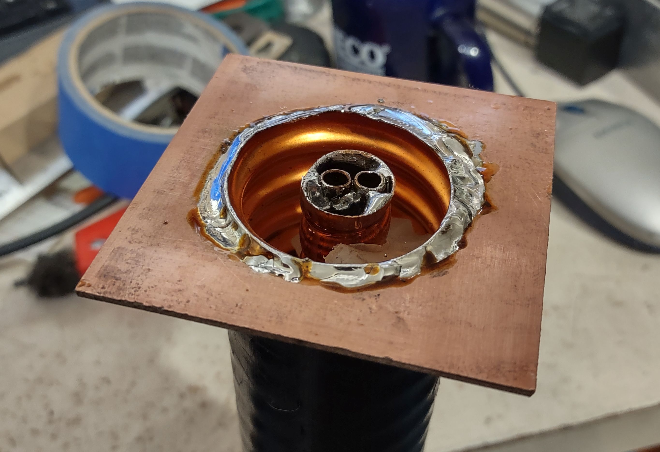
Figure 5: The PC Board plate soldered to the end of the coax. This is from the band-pass version, but you get the idea! Click on the image for a larger version.
No matter which type of coax center you are using, using
a hot soldering iron or gun, solder the tube for the coupling capacitor inside the Heliax's center conductor, the end
flush with the end of the center conductor: A pair of sharp
needle-nose pliers to hold it in place is helpful in this task. Remember that you are soldering to a large chunk of copper, so you'll need a fair bit of heat to be able to make a proper connection!
Making a box:
On the "business" (non-shorted)
end of the piece of cable we need to make a simple box with a solid
electrical connection to the outer shield to which we can mount the RF
connectors with good mechanical stability. For the 1-5/8" cable, I cut a
piece of 0.062" (1.58mm) thick double sided glass-epoxy circuit board material into a square that was 3" (75mm) square and using a ruler, drew lines on it from the opposite corners to form an "X" to find the center.
Using a drill press, I used a 1-3/4" (45mm) hole
saw to cut a hole in the middle of this piece of circuit board
material, using a sharp utility knife to de-burr the edges and to
enlarge it slightly so that it would snugly fit over the outside of the
cable shield: You will want to carefully pick the size of hole saw to
fit the cable that you use - and it's best that it be slightly
undersized and enlarged with a blade or file than oversized and loose.
Figure 6: Bottom side of the solder plate showing the connection to the coax. Click on the image for a larger version.
After cleaning the outside of the coaxial cable and both sides of the circuit board material, solder it to the (non-shorted)
end on both sides of the board, almost flush with just enough of the
shield protruding through the top to solder it. For this, a bit of flux
is recommended, using a high-power soldering iron or gun - and it's
suggested that it first be "tacked" into place with small solder joints
to make sure that it is positioned properly.
Adding sides and connectors:
With the base of the box in place, cut four sides, each being 1-3/8" (40mm) wide and two of them being 3" (75mm) long and the other two being 2-1/2" (64mm)
long. First, solder the two long pieces to the top, using the shorter
pieces inside to space and center them - and then solder the shorter
pieces, forming a five-sided (base plus four sides) box atop the piece of cable.
Figure 7: A look inside the box showing the connection to the center of the capacitor, the "tuning" strips and ceramic trimmer. Click on the image for a larger version.
Resonator adjustment capacitor:
You will need to be able to make slight adjustments to the frequency of the center conductor of the Heliax resonator. If all goes well, you will have cut the coaxial cable to be slightly short - meaning that it will resonate entirely above the 2 meter band. The installation of the coupling capacitor will lower that frequency significantly - but it should still be above the frequency of interest so a means for "fine tuning" is necessary.
Figure 7 shows two strips of copper: One soldered to the center conductor (the sleeve of the coupling capacitor, actually) and another soldered to the inside for the Heliax shield. These to plates are then moved closer/farther away to effect fine-tuning: Closer = lower frequency, farther = higher frequency. Depending on how far you need to lower the frequency, you can make these "plates" larger or smaller - or if you can't quite get low enough in frequency with just one set of these "plates", you can install another set.
NOTE: It is recommended that you do NOT install the copper strips for tuning just yet: Go through the steps below before doing so.
If your resonant frequency is too low - don't despair yet: It's very likely that you'll have to reduce the coupling capacitor a bit (e.g. pull it out of the tubing and/or cut it a bit shorter) and this will raise the frequency as well.
How it's connected:
A single notch cavity is typically connected on a signal path using a "Tee" connector as can be seen in Figure 1: At the notch's resonant frequency, the signal is literally "shorted out", causing attenuation.
As can be seen in Figure 7, there is only one connector (BNC type) on our PC board box - but we could have easily installed two BNC connectors - in which case we would run a wire from one connector to the center capacitor as shown and then run another wire from the capacitor to the other connector.
Adjusting it all:
For this, I am presuming that you have a NanoVNA or similar piece of equipment: Even the cheapest NanoVNA - calibrated according to the instructions - will be more than adequate in allowing proper adjustment and measurement of this device.
Using two cables and whatever adapters you need to get it done, put a "Tee" connector on the notch filter and connect Channel 0 on one side of the Tee and Channel 1 on the other side of the Tee and put your VNA in "through" mode. (Comment: There are many, many web pages and videos on how to use the NanoVNA, so I won't go through the exact procedure here.)
Configure the VNA to sweep from 10 MHz below to 10 MHz above the desired frequency and you should see the notch - hopefully near the intended frequency: If you don't see the notch, expand the sweep farther and if you still don't see the notch, re-check connections and your construction.
At this point, "zoom in" on the notch so that you are sweeping, say, from 2 MHz below to 2 MHz above and carefully note the width and depth of the notch. Now, pull out the center capacitor (the one made from the guts of RG-8 or RG-6 cable) a slight amount: The resonant frequency will move UP when you do this.
The idea here is to reduce the coupling capacitance to the point where it is optimal: If you started out with too much capacitance in the first place, the depth of the notch will be somewhat poor (20dB or so) and it will be wider than desirable. As the capacitance is reduced, it should get both narrower and deeper. At some point - if the coupling capacitance is reduced too much - the
notch will no longer get narrower, but the depth will start to get
shallower.
Comment: You may need to "zoom in" with the VNA (e.g. narrow the sweep) to properly measure the depth of the notch. As the VNA samples only so many points, it may "miss" the true shape and depth of the notch as it gets narrower and narrower.
The "trick" with this step is to pull a bit of the coax center out of the coupling capacitor and check the measurement. If you need to pull "too much" out (e.g. there's a loop forming where you have excess) then simply unsolder the piece, trim it by 1/4-1/2" (0.5-1cm), reinstall, and then continue on until you find the optimal coupling.
It's recommended that when you do approach the optimal coupling, be sure that you have a little bit of adjustment room - being able to push in/pull out a bit of the capacitor for subsequent fine tuning.
At this point your resonant (notch) frequency will hopefully be right at or higher than your target frequency: If it is too low, you may need to figure out how to shorten the resonator a bit - something that is rather difficult to do. If you already added the "capacitor plates" for fine-tuning as mentioned above, you may need to adjust them to reduce the capacitance between the ground and the center conductor and/or reduce their size.
Presuming that the frequency is too high (which is the desirable state) then you will probably need to add the copper capacitor strip plates as describe above, and seen in Figure 7. You should be able to move the resonant frequency down toward your target by moving the plates together. Remember: It is the proximity of the plate connected to the center conductor of the resonator to the ground that is doing the tuning! If you can't get the frequency low enough, you can add more strips to the center conductor - but you will probably want to remove the coupling capacitor (e.g. the coax center conductor) to prevent melting it when soldering.
Optimizing for "high" or "low" pass:
As described above, the notch will be more or less symmetrical - but in most cases you will want a bit of asymmetry - that is, you'll want the effect of the notch to diminish more on one side than the other. Doing this allows you to place the notch frequency (the one to block) and the desired frequency (the one that you want) closer together without as much attenuation.
Figure 8: The simplest form of the "high pass" notch, used during initial testing of the concept - See the results in Figure 9. Click on the image for a larger version.
"High-pass" = Parallel capacitor
In our case - with the higher of the two notches as 145.01 MHz and the desired signal at 147.82 MHz, we want the attenuation to be reduced rapidly above the notch frequency to avoid attenuating the 147.82 signal - and this may be done by putting a capacitor in parallel with the center of the coupling capacitor and ground: A careful look at Figure 7 will reveal a small ceramic trimmer capacitor.
This configuration is more clearly seen in Figure 8: There, we have the simplest - and kludgiest - possible form of the notch filter where you can see two ceramic trimmer capacitors connected across the center coupling capacitor and the center pin of the BNC connector. Off the photo (to the upper-left) was the connection to a "tee" connector and the NanoVNA. If you just want to get a "feel" for how the notch works and tunes, this mechanically simple set-up is fine - but it is far too fragile and unstable for "permanent" use.
For 2 meters, a capacitor that can be varied form 2-35pF or so is usually adequate - the higher the capacitance, the more effect there is on the asymmetry - but at some point (with too much capacitance) losses and filter "shape" will start to degrade - particularly with inexpensive ceramic and plastic trimmer capacitors. Ideally, an air-type variable capacitor is used, but an inexpensive ceramic trimmer will suffice for receive-only applications - and if the separation is fairly wide, as is the case here. For transmit applications, the air trimmer - or a high-quality porcelain type is recommended.
"Low-pass" = Parallel inductor
While the parallel capacitor will shift the shape of the notch's "shoulders" for "low notch/high pass" operation, the use of a parallel inductor will cause the response to become "low pass/high notch" where the reduced attenuation is below the notch frequency. If we'd needed to construct a notch filter to keep the 147.22 repeater's transmit signal out of the 145.01 packet's receiver, we would use a parallel inductor.
It is fortunate that an inductor is trivial to construct and adjust. For 2 meters, one would start out with 4-5 turns wound on a 3/8" (10mm) drill bit using solid-core wire of about any size that will hold its shape: 12-18 AWG (2-1mm diameter) copper wire will do. Inductance can be reduced by stretching the coil of wire and/or reducing the number of turns. As with the capacitor, this adjustment is iterative: Reducing the inductance will make the asymmetry more pronounced and with lower inductance, the desired frequency and the notch frequency can be placed closer together - but decrease the inductance too much, loss will increase.
Comment: The asymmetry of the "pass" and "notch" is why some of the common repeater duplexers have the word "pass" in their product description: It simply means that on one side of the notch or the other the attenuation is lower to favor receive/transmit.
Results:
Figure 9: VNA sweep of one of the prototype notch filter depicted in Figure 8. This shows the asymmetric nature of the notch and "pass" response (blue trace) when a parallel capacitor is used. The yellow trace shows the low SWR at the pass frequency. Click on the image for a larger version.
Figure 9 shows a the sweep of the assembly shown in Figure 8 from a NanoVNA screen.
The blue trace shows the attenuation plot: At the depth of the notch (marker #1) we have over 24dB of attenuation, which is about what one can expect from a notch cavity simply "teed" into the NanoVNA's signal path.
We can also see the asymmetry of the blue trace: Above the notch frequency we see Marker #2 - which is a few MHz above the notch and how the attenuation decreases rapidly - to less than 0.5dB. In comparison the blue trace below the notch frequency has higher attenuation near the notch frequency.
If you look carefully you'll also notice that just above the notch frequency, the attenuation (blue trace) is reduced to the lowest value right at the desired pass frequency: This is our goal - set the notch at the frequency we want to reject and then set the parallel inductor or capacitor to the value that yields the lowest attenuation and lowest VSWR (the yellow trace) at the frequency that we want to pass.
Again, if we'd placed an inductor across the circuit rather than a capacitor, this asymmetry would be reversed and we'd have the lower attenuation below the notch frequency.
Note: This sweep was done with the configuration depicted in Figure 8 at whatever frequency it happened to resonate "near-ish" 2 meters to test how well everything would work. Once I was satisfied that this notch filter could be useful, I rebuilt it into the more permanent configuration and tuned it properly, onto frequency.
Putting two notches together:
Because we needed to knock down both 144.39 and 145.01 MHz, we can see from the Figure 9 that we'd need two notch filters cascaded to provide good attenuation and not affect the 147.82 MHz repeater input frequency. A close look at Figure 1 will reveal that these two filters are, in fact, cascaded - the signal from the antenna (via the receiver branch of the repeater's duplexer) coming in via one of the BNC Tees and going out to the receiver via another.
The cable between the two notches should be an electrical quarter wavelength - or an odd multiple thereof (e.g. 3/4, 5/4) to maximize the effectiveness of the two notches together: Since we only need a very short cable, we can use 1/4 wavelength here. A quarter wave transmission line has an interesting property: Short out one end and the impedance on the other end goes very high - and vice-versa. To calculate the length of a quarter-wave line we can use some familiar formulas:
300/Frequency (in MHz) = Wavelength in meters
If we plug 145 MHz into the above equation (300/145) we get a length of 2.069 meters (multiply this by 3.28 and we get 6.79 feet).
Since we are using coaxial cable, we need to include its velocity factor. Since the 1/4 wave jumper is foam-type RG-8X we know that its velocity factor is 0.79 - that is, the RF travels 79% of the speed of light through the cable, meaning that it should be shorter than a wavelength in free space, so:
2.069 * 0.79 = 1.63 meters (5.35')
(Solid dielectric cable - like many types of RG-8 and RG-58 will have a velocity factor of about 0.66, making a 1/4 wave even shorter! There are online tables showing the velocity factor of many types of cable - refer to one of these if you aren't sure of the velocity factor of your cable.)
Since this is a full wavelength, we divide this length by 4 to get the electrical quarter-wavelength:
1.63 / 4 = 0.408 meters (16.09")
As it turns out, the velocity factor of common coaxial cables can vary by several percent - but the length of a quarter-wave section is pretty forgiving: It can be as much as 20% off in either direction without causing too much degradation from the ideal (e.g. it will work "Ok") - but it's good to be as precise as possible. When determining the length of the 1/4 wave jumper, one should include the length to the tips of the connectors, not just the length of the cable itself.
Figure 10: The response of the two cascaded notch filters - one tune to 144.39 and the other to 145.01 MHz. Click on the image for a larger version.
Because we know that the notch filters present a "short" at their tuned frequency, that means that the other end of a 1/4 wave coax at that same point will go high impedance - making the "shorting" of the second cavity even more effective. In testing - with the two notches tuned to the same frequency, the total depth of the notch was on the order of 60dB - significantly higher than the sum of the two notches individually - their efficacy improved by the 1/4 wave cable between them.
As we needed to "stagger" the two notches to offer best attenuation at the two packet frequencies, the maximum depth was reduced, but as can be seen in Figure 10, the result is quite good: Markers 1 and 2 show 144.39 and 145.01 MHz, respectively with more than 34 dB of attenuation: The two notches are close enough to each other than there is some added depth by their interaction. Marker 3 at the repeater input frequency of 147.82 has an attenuation of just 0.79dB - not to bad for a homebrew filter made from scrap pieces!
Comment: If you are wondering of the 0.79dB attenuation was excessive, consider the following: Many repeaters are at shared sites with other users and equipment - in this case, there were two other land-mobile sites very nearby along with a very large cell site. Because of this, there is excess background noise generated by this other gear that is out of control of the amateur repeater operator - but this also means that the ultimate sensitivity is somewhat limited by this noise floor. Using an "Iso-Tee", it was determined that the sensitivity of this repeater - even with coax, duplexer and now notch filter losses - was "site noise floor limited" by a couple of dB, so the addition of this filter did not have any effect on its actual sensitivity.
Putting it together:
Looking again at Figure 1, you will noticed that the two notches filters are connected together mechanically: Short pieces of PVC "wood" (available from the hardware store) were cut and a hole saw was used to make two holes in each piece, slipped over the end and then secured to the notch assemblies with RTV ("Silicone") adhesive.
Rather than leaving the tops of the PC board boxes open where bugs and debris might cause detuning, they were covered with aluminum furnace tape which worked just as well as soldering a metal lid would have - plus it was cheap and easy! (The boxes were deep enough that the proximity of metal - or not - at the top had negligible effect on the tuning of the resonators.
Did it work?
At the time we installed the filter, the packet stations were down, so we tested the efficacy of the filter by transmitting at high power on the two frequencies alternately from an on-site mobile-mounted transceiver. Without the filter, a bit of desense from this (very) nearby transmitter was noted in the receiver, but was absent with it inline.
With at least 34dB of attenuation at either packet frequency we were confident that the modest amount of desense (on the order of 10-15dB - enough to mask weak signals, but not strong ones) - IF it was caused by receiver overload - would be completely solved by attenuating those signals by a factor of over 2000. If it had no effect at all, we would know that it was, in fact, the packet transmitters generating noise.
Some time later the packet stations were again active - but causing a bit of desense, but this was not unexpected: At the start, we were not sure if the cause of the desense was due to the repeater's receiver being overloaded, or noise from the packet transmitter - but because the amount of desense was the same after adding the notch filter we can conclude that the source of desense was, in fact, noise from the packet transmitters.
Having done due diligence and installed these filters on our receiver, we could then report back to the owner of the packet transmitters what we had done and more authoritatively request that they install appropriate filtering on their transmitters (notch or pass cavities - preferably the latter) in order to be good neighbors, themselves.
* * *
"I have 'xxx' type of cable - will it work?"
The
dimensions given in this article are approximate, but should be
"close-ish" for most types of air and foam dielectric cable. While I
have not constructed a band-pass filter with much smaller Heliax-like cable such as
1/2" or 3/4", it should work - but one should expect somewhat lower
performance (e.g. not-as-narrow band-pass with higher losses) - but it may still be useful. With these smaller cables you may not be able to put the coupling inside the center conductor, so you'll have to get creative.
Because
of the wide availability of tools like the NanoVNA, constructing this
sort of device is made much easier and allows one to characterize both
its insertion loss and response as well as experimentally determining
what is required to use whatever large-ish coaxial cable that you might
have on-hand.
"Will this work on (some other band)?"
Yes,
it should: Notch-only filters of this type were constructed for a 6
meter repeater - and depending on your motivation, one could also build
such things for 10 meters or even the HF bands!
It is likely that,
with due care, that one could use these same techniques on the 222 MHz
and 70cm bands provided that one keeps in mind their practical
limitations.
* * *
Related articles:
A 2-meter band-pass cavity using surplus Heliax - link - This article describes constructing a simple band-pass filter using 1-5/8" Heliax. The techniques used in that article are the same as those applied here.
Second Generation Six-Meter Heliax Duplexer by KF6YB - link - This article describes a notch type duplexer rather than pass cavities, but the concerns and construction techniques are similar.
When Band-Pass/Band-Reject (Bp/Br) Duplexers really aren't bandpass - link
- This is a longer, more in-depth discussion about the issues with such
devices and why pass cavities should be important components in any
repeater system.
The SDRPlay RSP2pro (left) and RSP1a receivers (right)
The SDRPlay RSP1a is a popular Software Defined Radio (SDR). This device, connected to and powered by the computer via a USB cable covers from VLF through UHF and low microwave frequencies.
This receiver shares a similar internal architecture of similar devices such as the RTL-SDR dongle and the AirSpy in that an analog frequency converter (mixer) precedes the analog-to-digital converter: In the case of the SDRPlay, the frequency to which the receiver is tuned is (usually) converted to baseband I/Q signals, with the "center" frequency being at zero Hz (DC).1
Note:
For the purposes of this discussion, there is no difference between the RSP1a and some of the other receivers in the product lineup (e.g. RSPDuo, RSPdx and the discontinued RSP1, RSP2 and RSP2pro) in terms of harmonic response across the 2-30 MHz range as they all have about the same 12 MHz and 30 MHz cut-off frequencies on their input filtering - properties that would affect HF reception across the 2-30 MHz range in terms of harmonic response.
By its nature, a frequency mixer is a non-linear device. Ideally, the two frequencies applied to a mixer would yield just two more - the sum and difference. For example, if we applied a 5 MHz signal and a 1 MHz signal to a mixer, it would output both the sum of 6 MHz and the difference of 4 MHz - and this is true, but there's more to the story.
In our example - with a real-world mixer, we will also get additional products - including those related to the harmonics of the local oscillator and the applied signal. Because of this, we will see weaker signals at:
11 MHz (2 * 5 MHz + 1 MHz)
9 MHz (2 * 5 MHz - 1 MHz)
7 MHz (5 MHz + 2 * 1 MHz)
3 MHz (5 MHz - 2 * 1 MHz)
And so on.
Typically, these "other" signals will be quite a bit weaker than the original - but they will still be present, possibly at a high enough level to cause issues such as spurious signals - a problem with both receivers and transmitters. Typically, these are tamed by proper design of the mixer, proper selection of frequencies and careful filtering around the mixer to limit the energy of these "extra" signals.
Note: There will be a response at 5x the center frequency as well, but it is suppressed better than the 3x response by the mixer and - for the 80 meter amateur band and higher - these responses are suppressed reasonably well by the filtering.
SDRPlay's poor harmonic response suppression on 80 meters and below.
ANY receiver will experience spurious responses related to mixing products. Typically, filtering is employed to remove/minimize such responses, but for a wide-bandwidth receiver such an SDR, doing this is complicated by the fact that being able to cover wide swaths of bandwidth would ideally require a large number of overlapping filters.
An example of a radio where this is done - albeit of different architecture - is the Icom IC-7300 which has nine overlapping band-pass filters that cover 160 through 10 meters. While the reasons for the '7300 having many filters has as much to do with its being a "direct sampling" 2 type of SDR, good filtering on the signal path of any type of receiver - SDR or "HDR" (Hardware Defined Radio - or an "old school" analog type) is always a good idea
If this many filters had been implemented on the SDRPlay, there would be enough filtering to prevent a significant harmonic response. In the case of the RSP1a, this was not done - partly to allow 5-8 MHz of continuous coverage without being significantly impacted by the filters in many cases, but more likely it was done due to practical reasons of economics3: There are just three filters used for covering all of the "HF" amateur bands 160 through 10 meters: One that covers up to 2 MHz, another that covers 2-12 MHz and third that covers 12-30 MHz: This information is covered in the RSP1a technical information document (https://www.sdrplay.com/wp-content/uploads/2018/01/RSP1A-Technical-Information-R1P1.pdf )
The sensitivity to harmonics was tested with the RSP1a's local oscillator (but not necessarily the virtual receiver) tuned to 3.7 MHz 4. For reasons likely related to circuit symmetry, it is odd harmonics that will elicit the strongest response which means that it will respond to signals around (3.7 MHz * 3) = 11.1 MHz. "Because math", this spurious response will be inverted spectrally - which is to say that a signal that is 100 kHzabove 11.1 MHz - at 11.2 MHz - will appear 100 kHz below 3.7 MHz at 3.6 MHz. (It's likely that there are also weaker responses at frequencies around 5 times the local oscillator, but these are - for the most part - adequately suppressed by the filtering.)
In other words, the response to spurious signals follow this formula:
Apparent signal = Center frequency + ((Center frequency * 3) - spurious signal) )
Where:
Center frequency = The frequency to which the local oscillator on the RSP is tuned. In the example above, this is 3.7 MHz.
Spurious signal = The frequency of spurious signal which is approximately 3x the center frequency. In the example above, this is 11.2 MHz.
Apparent signal = Lower frequency where signal shows up. In the example above, this is 3.6 MHz.
In our example - a tuned frequency of 3.7 MHz - the 3rd harmonic would be within the passband of the 2-12 MHz filter built into RSP1a meaning that the measured response at 11.2 MHz will reflect the response of the mixer itself, with little effect from the filter as the 2-12 MHz filter won't really affect the 11 MHz signal - and according to the RSP1a documentation (link), this filter really doesn't "kick in" until north of 13 MHz.
In other words, in the area around 80 meters, you will also be able to see the strong SWBC (Shortwave Broadcasting) signals on the 25 meter band around 11 MHz.
How bad is it?
Measurements were taken at a number of frequencies and the amount of attenuation is indicated in the table below. These values are from measurement of a recent-production RSP1a and spot-checking of a second unit using a calibrated signal generator and the "HDSDR" program:
LO Frequency
Measured Attenuation at 3X LO frequency
Attenuation in "S" Units
2.1 MHz
21 dB (@ 6.3 MHz)
3.5
2.5 MHz
21 dB (@ 7.5 MHz)
3.5
3.0 MHz
21 dB (@ 9.0 MHz)
3.5
3.7 MHz
21 dB (@ 11.1 MHz)
3.5
4.1 MHz
23 dB (@ 12.3 MHz)
3.8
4.5 MHz
30 dB (@ 13.5 MHz)
5
5.0 MHz
39 dB (@ 15.0 MHz)
6.5
5.5 MHz
54 dB (@ 16.5 MHz)
9
6.0 MHz
54 dB (@ 18.0 MHz)
9
6.5 MHz
66 dB (@ 19.5 MHz)
11
12.0 MHz
21 dB (@ 36.0 MHz)
3.5
12.5 MHz
21 dB (@ 37.5 MHz)
3.5
13.5 MHz
22 dB (@ 40.5 MHz)
3.7
14.5 MHz
26 dB (@ 43.5 MHz)
4.3
15.5 MHz
31 dB (@ 46.5 MHz)
5.2
16.5 MHz
35 dB (@ 49.5 MHz)
5.8
17.5 MHz
39 dB (@ 52.5 MHz)
6.5
18.5 MHz
43 dB (@ 55.5 MHz)
7.2
19.5 MHz
46 dB (@ 58.5 MHz)
7.7
20.5 MHz
50 dB (@ 61.5 MHz)
8.3
21.5 MHz
53 dB (@ 64.5 MHz)
8.8
Table 1: Measured 3rd harmonic response of the RSP1a
Interpretation:
In the above chart we see the local oscillator frequency in the left column, the measured attenuation of the 3rd harmonic response (and its frequency) in the center column, and that amount of attenuation expressed in "S" units. Here, an "S" unit is based on the IARU standard (Technical recommendation R.1) of 6 dB per S unit, which is reflected in programs like SDRUNO, HDSDR and many others.
The attenuation of the 3rd harmonic response was measured by first noting the signal level required to obtain a given reading - typically "S-9" near the fundamental frequency - and then observing the level required to obtain that same reading - within +/-1dB - near the 3rd harmonic frequency, using the relationship formula, above.
Below the cutoff frequency of the relevant filter (nominally 12 MHz for receive frequencies in the range of 2 to 12 MHz, nominally 30 MHz for receive frequencies in the range of 12 to 30 MHz) the harmonic response is limited to that of the mixer itself, which is 21 dB.
We can see that on the 2 to 12 MHz segment, the attenuation related to the 3rd harmonic doesn't exceed 40 dB (which is the low end of what I would call "OK, but not great) until one gets above about 5 MHz (which translates to 15 MHz) and it doesn't get to the "goodish" range (50dB or more) until north of about 5.5 MHz which is borne out by the filter response charts published by SDRPlay.
On the 12 to 30 MHz band the filter has practically negligible effect until one gets above about 20 meters, at which point it gets into the "OK, but not great" range by about 18 MHz, and it doesn't really get "goodish" until north of 20.5 MHz. What this means is that strong 6 meter signals may well appear in the 16.5 to 17.5 MHz range as frequency inverted representations.
If there is a relatively strong signal source in the area of the 3rd harmonic response, it will likely appear at the lower receive frequency where the attenuation of the filter is less than 40 dB or so. The severity of this response will, of course, depend on the strength of that signal, the amount of attenuation afforded by the filters at that frequency, and the amount of noise and other signals present in the range of the fundamental frequency response.
Based on the above data, we can deduce the following:
When the RSP1a is tuned between 2 MHz and (below) 12 MHz, it is using its "2-12 MHz" filter. In this range - and below approx. 4 MHz - the 12 MHz cut-off of the filter has negligible effect in reducing 3rd harmonic response.
What this means is that signals from 6-12 MHz will appear more or less unhindered (aside from the 21 dB reduction afforded by the mixer) when the local oscillator of the receiver is tuned between 2 and 4 MHz.
The 3rd harmonic response across 2-4 MHz - which is the 6-12 MHz frequency range - can contain quite a few strong signals and noise sources such as those from shortwave broadcast stations.
When the RSP1a is tuned between 12 MHz and (below) 30 MHz, it is using its "12-30 MHz" filter. Below about 14 MHz, the 30 MHz cut-off of the filter has negligible effect in reducing 3rd harmonic response.
Signals from 36-40 MHz will appear with just 21-26 dB attenuation when tuned in the range of 12-13.5 MHz.
In most cases there are probably few signals in the 36-40 MHz range that are likely to be an issue when tuning in the 12-13.5 MHz range.
80 meter example:
Connecting
the RSP1 to a known-accurate signal generator set to -40dBm, the signal
level at 3.6 MHz was measured: Maintaining the signal level, the
generator was retuned to 11.2 MHz and the resulting signal level was measured to be 21 dB (a bit more than 3 "S" units) lower than that at 3.6 MHz.
What
this means is is that a "20 over S-9" signal at 11.2 MHz will show up
as an S-9 signal at 3.7 MHz, and an S-9 signal at 11.2 MHz will be
around S-6 at 3.7 MHz. In other words, even a "weak-ish" signal at the 3rd harmonic will show up at the lower frequency.
80/60 meter example:
If you run the RSP1a in a wider bandwidth mode, it is possible to simultaneously see and tune a greater frequency range. For example, let us presume that you wish to cover both 80 and 60 meters using a single RSP1. To do this, you could set the center (LO) frequency to 4.5 MHz and set the sample rate to 5.376 MHz and use the 5 MHz band-pass filter built into the RSP1's converter/mixer chip (the Msi001) to prevent in-band aliasing.
In this configuration 20 meter signals will appear at the top of 80 meters owing to the relationship in the formula that we described above. Taking the 20 meter FT-8 subband at 14.074 MHz as an example, we see that:
4.5 MHz + ((4.5 MHz * 3) - 14.074) = 3.926 MHz
In other words, we will see spectrally-inverted representations of 20 meter FT-8 signals around 3.926 MHz, and the rest of the (upper) portion of 20 meters across the rest (lower) portion of 80 meters where USB signals on 20 meters will show up as LSB signals on 80. We know from the chart above that those signals will be attenuated by between 30 and 39 dB (about 5-6 S-units). This might sound like a lot of attenuation, but it means that a "20 over" signal on 20 meters will appear at around S-7 to S-8 on 80 meters - still quite respectable.
More about filtering and harmonic response
While these spurious responses may not be too much of a problem for the casual user, it will be necessary to add additional filtering to allow the RSP1a to function on par with a modern, SDR receiver from one of the major manufacturers.
Unfortunately, the filtering in the RSP1a is not sufficient in the 80 meter case mentioned above as it doesn't have octave filters (or similar) - but what about 60 or 40 meters?
The table above answers this question. In the case of 60 meters - with the receiver tuned to 5.3 MHz - our 3rd harmonic will land on 15.9 MHz. Based on measurements of the receiver the response of signals around 15 MHz - which corresponds to the 19 meter Shortwave Broadcast Band - will be a bit more than 40 dB down from 40 meters with about 20 dB of this being due to the roll-off of the 2-12 MHz filter - but because this frequency range is inhabited by very strong shortwave broadcasters they are likely to still be quite audible around 60 meters.
The situation is a bit better for 40 meters where the 3rd harmonic is around the 15 meter band. There, the 2-12 MHz filter knocks signals down by 50dB or more, putting them about 70dB below the 40 meter response - on par with about any respectable receiver.
What this means is that for amateur bands below 40 meters it is suggested that additional filtering be applied.
The best solution - and recommended for any software-defined radio (or even older "hardware-defined radios") is to have band-pass filter designed for the specific amateur band in question. This will not only significantly attenuate the harmonic response, but it will also reduce the total amount of RF energy entering the receiver, reducing the probability of overload. The obvious down-side is that it will reduce the flexibility of the receiver in that unless you change/remove it, you won't be able to receive signals well outside the filter's design range.
Another possibility is to add a low-pass filter that is designed to cut off signals above the band of interest. For example, if you have a filter that cuts off sharply above 8 MHz, you will be able to tune 80-40 meters and get reasonable attenuation of the 3rd harmonic response across this entire frequency range.
In the case of 160 meters the RSP1a will automatically select the 0-2 MHz low-pass filter and the 3rd harmonic response will be a respectable 50-ish dB down, depending on frequency.
On 20 meters - where the 3rd harmonic is around 42 MHz - the "12-30 MHz" filter will be selected, but the published response of this filter shows that at 42 MHz its attenuation will be quite limited. Practically speaking, it is unlikely that there will be any signals in this frequency range so there being "only" 20-30dB of attenuation is unlikely to cause a problem in most cases, but one should be aware of this.
What can be done:
In short, none of the currently-made SDRPlay receivers - by themselves - will offer very good performance in terms of harmonic rejection between 2 and 5 MHz and it will be particularly bad on the 80 meter band where strong 25 meter SWBC signals can appear: It is interesting that the ARRL review of the RSPdx (Link here) didn't catch this issue.
It is unfortunate that the designers of the SDRPlay receivers did not add at least one additional low-pass filter in the signal path to quash what is a rather strong response in the 2-6 MHz range - particularly on 80 meters, one of the most popular bands. A low-pass filter with a cut-off frequency of 6 MHz (with attenuation becoming significant above 7 MHz) would ameliorate the harmonic response when tuning across this band. This problem is made even worse by the fact that even antennas that aren't particularly resonant at their harmonic responses (e.g. the antenna for 80 meters) will likely do quite a decent job of receiving signals in the 11-12 MHz area.
The only real "fix" for this is to install additional filtering between the SDRPlay receiver and the antenna. If single-band operation is all that is desired, the best choice will be a band-pass filter designed for the frequency range in question5 - but unless you are dedicating the receiver just for that one band, this isn't really desirable unless you can easily switch/bypass the filter when tuning elsewhere.
A more flexible solution would be to use a low-pass filter. As we noted above, the 12 MHz roll-off of the built-in (2-12 MHz) filter just doesn't do much to suppress signals from 20 meters, but if we had a filter that had a sharp cut off beginning, say, at 8 MHz, we could use it for 80, 60 and 40 meters - such a filter is depicted schematically, below:
8 MHz low-pass filter schematic, designed using ELSIE
This filter is pretty easy to build:
Capacitors 1 and 5 each consist of a 100pF and 470pF in parallel
Capacitor 3 consists of a 680pf and 220pF in parallel - although you could probably get away with two 470pF capacitors in parallel in a pinch.
Inductors 2 and 4 consist of 16 turns on a T50-2 (or 18 turns on a T37-2) toroid using small wire - 24-30 AWG is fine
A small scrap of PC board material - about 2"x4" (5x10cm) is more than large enough to accommodate with the capacitors soldered directly to the foil and inductors held aloft by the capacitors. The connectors should be attached to the PC board directly - or with short lengths of coax, keeping the ground (shield) lead length to an absolute minimum to minimize the probability of ground-loop induced noise currents.
If you have access to a NanoVNA it's quite easy to check the performance. If anything, it may be necessary to spread the turns across the toroid or remove one turn - but this design is quite forgiving.
The obvious down-side for this is that if you are tuning all over the HF spectrum (above 7.5-8 MHz in the case of the filter above) you'd have to manually remove or bypass any such filtering when you tuned beyond the range that the added filter would pass.
Footnotes:
The receivers mentioned at the beginning of the article (SDRPlay, AirSpy HF, RTLSDR, etc.) have analog-to-digital converters that cover only a portion of the HF spectrum, using a frequency mixer to convert a range of frequencies from the range of interest to a lower frequency, which is then fed into the converter. Limiting the amount of spectrum being ingested by the receiver - particularly when appropriate filtering is used - can improve performance, reduce cost, and especially reduce the total amount of data, allowing a modest computer (older PC, Raspberry Pi) to be used with it.
A "direct sampling" type of receiver - such as that found in the Icom IC-7300, IC-7610, the KiwiSDR, Red Pitaya and the RX-888 (when used at HF) and others like them simply "inhale" large swaths of spectrum all at once. Because the analog-to-digital converter itself has a limited amount of total RF signal power that it can handle, radios like the Icoms have filtering that allow the passage of only the (relatively) small portion of the HF spectrum around that to which the receiver is tuned, reducing the probability of overload from strong signals on frequencies well away from those of interest. Other direct-sampling receivers such as the KiwiSDR, Red Pitaya and RX-888 do not necessarily have band-specific filtering as they are intended to be able to receive multiple frequencies across the entire HF spectrum at once and as such, much more care is required in implementation to prevent overload/distortion for these devices.
In the case of the (currently-produced) RSP receivers, the filtering varies depending on model: In the case of the RSP1a, it has a band-pass filter that covers 2-12 MHz while other models have used just a 12 MHz low-pass - the former being capable of rejecting AM broadcast band (e.g. mediumwave) signals from the input of the receiver when tuned to HF, and the latter not. Some units additionally have a separate "notch" (reject) filter that is designed to remove just AM broadcast-band signals. The situation described in this article - the reception of signals around 11 MHz when tuned to 80 meters - is related to the fact that the 2-12 MHz filter represents a 6:1 frequency range which means that over the lower portion of this spectrum, the 12 MHz cut-off of this filter cannot possibly remove responses to the third harmonic, hence the issue described here.
If you are using a program like SDRUno it may not be readily apparent to what frequency the receiver's local oscillator is tuned. If set to "Zero IF" mode, the local oscillator will be tuned at the same place as the center of the waterfall display when it is fully zoomed out - typically indicated by a slight line at the "Zero Hz" frequency there there is a slight amount of noise energy. By default, one cannot directly tune the local oscillator ("Zero IF" frequency) in SDRUno. If you use the "HDSDR" program by I2PHD (et al) you can independently tune the local oscillator and the frequency of the virtual receiver.
SDRPlay receivers are currently in use at a number of well known and public WebSDRs around the world as the "acquisition device" (e.g. receiver). In most cases these receivers - because they are used only for specific amateur bands - are preceded by a band-pass filter for the band that they are covering, completely eliminating issue noted in this article. It was during testing at one of these WebSDRs - a receiver on 80 meters that does not (yet) have additional filtering - that signals were noted across the 80 meter band in the middle of the day that should not have been there at all - and these signals were quickly realized to be the result of a harmonic response in the front end. These responses were then verified and quantified using two other RSP1a receivers (of different production runs) and test equipment during the preparation of this article. When it was convenient to do so, a low-pass filter with a cut-off frequency of 7.5 MHz was installed on this receiver, solving the image problems.
Part of a project on 1.2Ghz that will include this band-pass filter.
Main dimensions got online via the tool here: https://www.changpuak.ch/electronics/interdigital_bandpass_filter_designer.php
Some details of similar construction for different frequency range (ADS-B) here: https://keptenkurk.wordpress.com/2014/11/05/a-homebrew-1090mhz-ads-b-filter/
My construction:
Used FR4 double sided PCB for the sides and brass for elements, bottom and top
Online results example for dimensions:
And the outcome:
Regarding results; not the best optimization for attenuation but not bad either considering the dimensions and construction not to the greatest dimensional andards:
Figure 1: Close-in responses of various filter combinations Yellow: Duplexer-only Magenta: Bandpass-only Cyan: Duplexer + Bandpass Click on the image for a larger version.
There is a follow-up article to this one - "A simple VHF notch cavity from scraps of (large) heliax" - link.
The case for bandpass filtering
If you operate a repeater - or even a simplex radio such as a Packet node - that is located at a "busy" radio site, you'll no doubt be aware of the need for cavity-based filtering.
In the case of a repeater, the need is obvious: Filtering must be sufficiently "strong" to keep the transmit signal out of the receiver, and also to remove any low-level noise produced by the transmitter that might land on the receive frequency.
In the case of a packet or simplex node of some sort, a simple "pass" cavity is often required at a busy site to not only prevent its receiver from being overloaded by off-frequency signals, but also be a "good neighbor" and prevent low-level signals from your transmitter from getting into other users' receivers - not to mention the preventing of those "other" signal from getting back into your transmitter to generate spurious signals in its own right.
Comments:
In this discussion, a "band pass" filter refers to the passing of ONLY a narrow range of frequency near those of interest and at odd multiples of the lowest resonant frequency - but nothing else.
It is HIGHLY RECOMMENDED that anyone attempting to construct this type of filter get and learn to use a NanoVNA: Even the cheapest units (approximately $50US) - when properly set up - will be capable of the sorts of measurements depicted in this article.
A Band-Pass/Band-Reject (BpBr) duplexer may not be what you think!
A common misconception is that a typical repeater duplexer - even though it may have the words "band pass" written on its label or in its specifications - has a true "band pass" response.
Figure 1 shows a typical example of this fallacy. The yellow trace shows the response of a typical 2 meter duplexer where we can see a peak in response at the "pass" frequency and a rather deep notch at the frequency that we wish to reject.
The problem becomes more apparent when we look over a broader frequency range. Figure 2 shows the same hardware, but over a span of about 30 MHz to 1 GHz.
Figure 2: The same as in Figure 1 except over a wider frequency range showing the lack of off- frequency rejection of a "BpBr" duplexer (Yellow) that is significantly mitigated by the addition of a band-pass filter (Cyan) Click on the image for a larger version.
Keeping an eye on the yellow trace, you'll note that over most of the frequency range there is very little attenuation. What this means is that the "BpBr" filter doesn't exhibit a true pass response once you get more than a few MHz away from the design frequency.
I've actually had arguments with long-time repeater owners that disagreed with this assertion, but hadn't actually "swept" a duplexer over a wide frequency range: These days, with the availability of inexpensive test equipment like the NanoVNA, there's no good excuse for not determining this for yourself!
For more about this, see the related articlelinked here.
Why is this a problem?
In the "old days" radios that you would use at a repeater site were typically cast-off mobile radios - and even if you had a repeater, it was typically based on a mobile design. These older radios - often from the 80s or earlier - typically used a bank of narrowband (often Helical) filter elements, each tuned to the frequency of interest: If several frequencies were used, the system planners often placed then near each other so that they could be covered by the receivers' narrow filters without undue attenuation and because of this, one could "get away with" a duplexer with filtering that didn't offer a "true" pass-band response.
Most modern radios used in amateur repeaters are "broadband" in nature meaning that they often have rather wide receiver front-end filters: It is not practical to have electronically-tuned filters that are anywhere near as narrow as the Helical filters of the past which means that they simply lack the filtering to reject strong, off-frequency signals.
The poor filtering of some "new" radios:
When a modern radio is dropped in place of an old radio at a "busy" site with lots of other transmitters, disappointment is sometimes the result: The "new" radio may seem less sensitive than the old one - or it might seem that sensitivity varies over time. In reality, the "new" radio may well be being overloaded by the off-frequency signals that the old radio's resonator-based front-end easily filtered. What's worse is that the precise nature of this overload condition may be masked by the use of subaudible tones or digital tone squelch - and if this is a digital radio system like D-Star, Fusion or DMR, there may be no obvious clues at all as to the problem at hand unless one has the ability to measure and monitor the analog "baseband" from the receiver itself.
To be sure, if the receiver in question can operate in carrier-squelch analog mode, the usual techniques to determine overload (Iso-Tee measurements, injection of a weak carrier and observing SNR, etc.) may be employed to determine if there is an issue - but this, too, may be misleading as problems may be intermittent, showing up only when a combination of transmitters key up.
A simple pass cavity:
While not a panacea, the use of a simple pass-only cavity can go a long way to diagnose - even solve - some chronic overload issues - particularly if these have arisen when old gear was replaced. Suitable pass cavities are readily available for purchase new from a number of suppliers and used from auction sites - they are also pretty easy to make from copper and aluminum tubing - if you have the tools. Because of the rather broad nature of a typical pass cavity, temperature stability is usually not much of an issue in that its peak could drift hundreds of kHz and only affect the desired signal by a fraction of a dB.
Another material that could be used to make reasonable-performance pass cavities is larger-diameter hardline or "Heliax" (tm). Ideally, something on the order of 1-5/8" or larger would be used owing to its relative stiffness and unloaded "Q" and either air or foam dielectric cable may be used, the main difference being that the "Q" of the foam cable will be slightly lower and the cavity itself will be somewhat shorter.
Figure 3: Cutting the (air core) cable to length Click on the image for a larger version.
The "Heliax bandpass cavity" described here can be built with simple hand tools, and it uses a NanoVNA for tuning and final adjustment. While its performance will not be as good as a larger cavity, it will - in many cases - be enough to attenuate strong, out-of-band signals that can degrade receiver performance.
Using 1-5/8" "Heliax":
The "cavity" described uses 1-5/8" air-core "Heliax" - and it is necessary for the inner conductor to be hollow to accommodate the coupling capacitors. Most - but not all - cable of this size and larger has a hollow center conductor. Cables larger diameter than 1-5/8" should work fine - and are preferred - but smaller than this may not be practical - both for reasons of unloaded "Q" and also if the center conductor is solid or if its inside diameter cannot accommodate the coupling capacitors described later on.
Note: The KF6YB article linked below contains some length calculators for coaxial cable.
Preparing the "shorted" end:
For 2 meters, a piece of cable 18" long was cut. For the air dielectric, it's recommended that one cuts it gently with a hand saw rather than a power tool as the latter can "snag" and damage the center conductor.
Figure 4: The "shorted" end of the stub with the slits bent to the middle and soldered to the center conductor. Click on the image for a larger version.
For the "cold" (e.g. shorted) end, carefully (using leather gloves) remove about 3/4" (19mm) of the outer jacket and then clean the exposed copper shield with a wire brush, abrasive pad and/or sand paper. With this done, use a pair of tin snips cut slots about 1/2" (12mm) deep and 1/4" (6mm) wide around the perimeter. Once this is done, use a pair of needle nose pliers and remove every other tab, resulting is a "castellated" series of slots. At this point, using a pair of diagonal pliers or a knife, cut away some of the inner plastic dielectric so that it is about 1/2" (12mm) away from the end of the center conductor.
Now, clean the center conductor so that it is nice and shiny and then bend the tabs that were cut inwards so that they touch the center conductor. Using a powerful soldering iron (I used a 150 watter) or soldering gun - and, perhaps a bit of flux - solder the shield tabs to the center conductor all of the way around. It's best to do this with the section of coax laying on its side so that hot solder/metal pieces do not end up inside the coax - particularly if air-core cable is used. If you used acid-core flux, carefully remove it before proceeding.
With one end of the cable shorted you can trim back any protruding center conductor and file any sharp edges - again taking care to avoid getting bits of metal inside the cable or embedded in the foam. At some point, you should cover the shorted end with RTV (silicone) and/or good-quality electrical tape to prevent contamination by dust or insects.
Preparing the "business" end:
Figure 5: The "coupling tubes" soldered in place which receive the wires for coupling in/out. Click on the image for a larger version.
At this point, the chunk of coax should be trimmed again, measuring from the point where the center conductor is soldered to the shield: For air-core trim it to 17" (432mm) exactly and for foam core, trim it to 16-1/8" (410mm). Again, using a sharp knife and gloves, remove about 3/4" (19mm) of the outer jacket and, again, clean the outer conductor so that it is bright and shiny.
Making coupling capacitors:
We now need to make two capacitors to couple the energy from the "in" and "out" connectors to the center resonator and for this, I cut two 3" (75mm) long pieces of RG-6 foam TV coaxial cable and from each of these pieces, I removed and kept the center conductor and dielectric - removing any foil shield and then stripping about 1/2" (12mm) of foam from one end of each piece.
At this point, you'll need some small copper tubing: I used some 1/4" O.D. soft-drawn "refrigerator" tubing, cutting two 2" (50mm) lengths and carefully straightening them out. To cut this, I used a rotary pipe cutting tool which slightly swedged the ends - but this worked to advantage: As necessary, I opened up the end cut with the deburring blade of the rotary cutting tool just enough that it allowed the inner dielectric of the RG-6 to slide in and out with a bit of friction to hold it in place..
Comment:
The use of 1/4" (6mm) O.D. copper pipe and RG-6 center conductor/dielectric isn't terribly critical: A different-sized copper or brass pipe could be used as long as two parallel pieces will fit inside the center conductor of the Heliax - and that the chosen center conductor and dielectric of the coax you use to make the capacitor will fit somewhat snugly inside it.
The reason for the two copper tubes is to prevent the two capacitors made from the center of the RG-6 from coupling directly to each other as all energy must first resonate the center conductor. Using these tubes - soldered to the center conductor/resonator - prevents such direct coupling, and it offers good mechanical stability.
Figure 6: The PC Board plate soldered to the end of the coax. Click on the image for a larger version.
Using a hot soldering iron or gun, solder the two straightened pieces of tubing together, in parallel, making sure that the ends of the tubing that you adjust to snugly fit the outside diameter of the piece of RG-6 are at the same end. Once this is done, insert the two parallel pieces of tubing inside the Heliax's center conductor and solder them, the ends flush with the end of the center conductor, taking care not to heat them enough that they unsolder from each other: A pair of sharp needle-nose pliers to hold them in place is helpful in this task.
Making a box:
On the "business" (non-shorted) end of the piece of cable we need to make a simple box with a solid electrical connection to the outer shield to which we can mount the RF connectors with good mechanical stability. For the 1-5/8" cable, I cut a piece of 0.062" (1.58mm) thick double sided glass-epoxy circuit board material into a square that was 3" (75mm) square and using a ruler, drew lines on it from the opposite corners to form an "X" to find the center.
Using a drill press, I used a 1-3/4" (45mm) hole saw to cut a hole in the middle of this piece of circuit board material, using a sharp utility knife to de-burr the edges and to enlarge it slightly so that it would snugly fit over the outside of the cable shield: You will want to carefully pick the size of hole saw to fit the cable that you use - and it's best that it be slightly undersized and enlarged with a blade or file than oversized and loose.
Figure 7: Bottom side of the solder plate showing the connection to the coax. Click on the image for a larger version.
After cleaning the outside of the coaxial cable and both sides of the circuit board material, solder it to the (non-shorted) end on both sides of the board, almost flush with just enough of the shield protruding through the top to solder it. For this, a bit of flux is recommended, using a high-power soldering iron or gun - and it's suggested that it first be "tacked" into place with small solder joints to make sure that it is positioned properly.
When positioning the box, rotate it such that the two "capacitor tubes" that were soldered into the center conductor are parallel with one of the sides of the square - this to allow symmetry to the connectors: This is depicted in Figure 8 where the left-hand and right-hand tubes (more or less) line up with their respective coaxial connectors.
Adding sides and connectors:
With the base of the box in place, cut four sides, each being 1-3/8" (40mm) wide and two of them being 3" (75mm) long and the other two being 2-1/2" (64mm) long. First, solder the two long pieces to the top, using the shorter pieces inside to space and center them - and then solder the shorter pieces, forming a five-sided (base plus four sides) box atop the piece of cable. As seen in the photo, the "short" sides are parallel to the two tubes in the center conductor.
As can be seen in Figure 8, there is a piece of PC board material about 1/4-3/8" (6-10mm) wide that goes between the two walls with the BNC connectors. This piece provides a bit of stiffening, minimizing flexure of the two walls with the connectors when cables are connected which could change the orientation of the two "RG-6 capacitors" - and it provides a small degree of shielding between the input and output wires that form these capacitors.
Figure 8: Inside the box with coupling/tuning stubs and lines and stiffening bar installed. Note the orientation of the tubes. Click on the image for a larger version.
As can be seen in the picture, BNC connectors were used as they were convenient, but "N" type, SMA or even UHF connectors could be used - but the use of BNC connectors will be described.
The BNC connectors were mounted on opposite sides of the box, approximately 3/8" to the left of the center line and 3/4" from the bottom. As can be seen in the photo, the connectors were mounted in the "short" wall of the box such that our "RG-6" capacitors more or less line up with the capacitor tubes.
Now, insert the ends of the RG-6 center conductor into the "capacitor tubes" and, bending the top in an "L" shape, solder the end with the exposed center conductor to the coaxial connectors.
Also visible in Figure 8 - just to the right of the center conductor - are two pieces of copper strip, each about 3/4" (20mm) wide - one is soldered to the center conductor and the other to the ground inside the box. These two tabs form a very simple capacitor which may be used to "fine tune" the center frequency of the pass response by bending them nearer/closer to each other. While most of the adjustment of the center tuning will occur as one slides the two capacitors (made from RG-6) in and out, this method may also be used to provide a bit of additional tuning range.
Preliminary adjustment:
It is best to first set the RG-6 capacitors to obtain the desired pass response, taking into account the desired band-pass frequency, but once one has done this - and if the pass frequency is too high - one would then add the "copper tab" capacitors - perhaps more than one set. If the frequency is too low, see if you can obtain a suitable passband width (and acceptable insertion loss) by pulling these coupling capacitors out to raise the frequency: For most applications, an insertion loss of even 1 dB will not appreciably reduce receiver performance - particularly if the local noise at the site is rather high from other users and especially if the use of a band-pass filter like this is intended to minimize desense, anyway.
It is best to make them from metal (copper, brass) that is thick enough to not be springy on their own: Saving a piece and flattening the copper material from the shield of the 1-5/8" coax as you prepare it for use is suggested.
At this point we are ready to do some preliminary tuning - and this will require a NanoVNA or similar: It is presumed that the builder will have familiarity with the NanoVNA to make S11 VSWR and S12 insertion loss measurements on an instrument that has been properly calibrated at the frequency range in question.
Setting the NanoVNA to measure both VSWR and through-loss over a span of 130-160 MHz, connect it to the cable and you should see a pass response somewhere in the frequency range and if all goes well, the peak in the pass response will be somewhere in the 130-140 MHz range.
Adjusting the center frequency and passband response is an iterative process as reducing the coupling by pulling out the capacitors (the RG-6 center conductor) will also increase the frequency. Practically speaking, only about 3/8"-1/2" (9-12mm) of center conductor is needed at most to attain optimal coupling so don't be afraid to pull out more and more of the capacitors.
A bit of experimentation is suggested here to get the "feel" of the adjustment - and here are a few pointers:
Figure 9: The band-pass filter sitting against a Sinclair Q2220E 2-meter Duplexer - a good combination for receiver protection at a busy repeater site! Click on the image for a larger version.
Lowest SWR is obtained with the coupling capacitors are identically adjusted. If the SWR isn't below 1.5:1, try pulling out or pushing in one of the capacitors slightly to determine the effect - but move it only about 1/16" in each iteration. Generally speaking, pulling one out slightly is the same as pushing the other in slightly in terms of reducing VSWR.
The passband response will be narrower the less of the RG-6 center conductor is in the capacitor tubes - but the insertion loss will also go up.
The frequency will go up the more the passband response is narrowed by reducing the coupling capacitors.
With the lengths given (e.g. 17" for air-core 16-1/8" for foam core) the passband will be within the 2 meter band with the amount of coupling that will yield about 0.5-0.6 dB insertion loss. To a degree, you can "tune" the center frequency of the cavity by adjusting the coupling. It is recommended that you first tune for the bandpass response - and then tune it to frequency: See below for additional comments.
It is recommended that you use a little coupling as needed to obtain the desired response. For example, if the cavity is "over coupled", the insertion loss will be about 0.5dB, but this will go up only very slightly as the coupling is reduced and the response is narrowed. At some point the insertion loss will start to go up as the passband is further-narrowed.
As the coupling capacitor is pushed in, the resonant frequency will go down. If, even with the "tuning capacitor" (the copper strips)
are minimized in coupling, the frequency is too low, try pulling the
RG-6 capacitors out slightly to move it up in frequency: It's easy to
accidentally "over couple" the cavity by pushing them in too far and
causing it to tune low. It's likely that you can pull more of the RG-6
capacitors out and reducing coupling than you might first think and still
have acceptably-low insertion loss - and doing so will narrow the
passband response and improve ultimate off-frequency attenuation.
As mentioned above, it's recommended that the approximate passband width be set with the capacitors and if all goes well, the pass frequency can be adjusted with just the adjustment to the coupling with only a slight change in overall bandwidth. If, however, the desired "narrowness" results in a pass frequency above that which is desired, a simple "tab" capacitor can be constructed as shown in the photo.
Figure 10: The "close-in" response of the band-pass cavity. With the current settings providing a bit less than 0.5dB of attenuation at the center, it's rejection at the edges of the U.S. 2 meter band (144-148 MHz) is a bit over 8 dB. Click on the image for a larger version.
This capacitor consists of two parts: A 3/8" (10mm) wide, 3/4" (20mm) long piece of copper or brass sheet is soldered to the center conductor. The addition of this piece, alone, may lower the center frequency and bending this tab up and down can provide a degree of fine-tuning. If the center frequency is still too high, another 3/8" wide, 3/4" long piece can be soldered to the shield of the coax next to it and be bent such that it and the first piece form two plates of a simple capacitor, allowing even greater reducing in resonant frequency of the cavity.
With the preliminary tuning done, a bit of reinforcement of the box is suggested: A strip of copper circuit board material 3/8"-1/2" (9-12nn) wide is soldered between the inside walls of the box with the RF connectors. This strip minimizes the flexing of the walls with the RF connectors due to stresses on the connected cables which can change the orientation of the coupling capacitors and cause slight detuning.
With this reinforcement in place, do a final tweaking of the bandpass filter's tuning.
Final assembly:
As noted earlier, it's strongly suggested that the shorted end of the cavity be covered to prevent debris and insects from entering either the center conductor or, especially, the space between the shield and center conductor. This may be done using electrical tape or RTV (Silicone) adhesive.
Figure 11: A wider sweep showing the rejection at and below the FM broadcast band and up through 225 MHz. This filter, by itself, provides over 40 dB rejection at 108 MHz Click on the image for a larger version.
Similar protection should be done to the top of the box: A piece of brass or copper sheet - or a piece of PC board material could be tack-soldered into place - or even some aluminum foil tape could be used: The tuning should be barely affected - if at all - by the addition of this cover, but it is worth verifying this with a simple test-fit of the cover.
Additional comments:
While the performance will vary depending on the coupling and tuning, the prototype, tuned for a pass response at 146.0 MHz, performed as follows:
Insertion loss at resonance: <0.5dB
-3dB points: -88 kHz and +92 kHz
-10dB points: -2.5 MHz and +2.75 MHz
-20dB points: -7.6 MHz and +11 MHz
2:1 VSWR bandwidth: 600 kHz
Loss <=108 MHz: 40dB or greater
More detail about the response of this cavity filter may be seen in figures 10 and 11. In the upper-left corner of each figure may be found the measured loss and VSWR at each of the on-screen markers.
If a higher insertion loss can be tolerated, the measured bandwidths will be narrower. Depending on the situation, an extra dB or two of path loss may be a reasonable trade-off for improved off-frequency rejection - particularly on a noisy site where the extra loss won't result in a degradation of system sensitivity due to the elevated noise floor and the improved selectivity reduces off-frequency signals even more.
As with any cavity-type filter, there is a bit of fragility in terms of frequency stability with handling. If, after it is tuned this - or any cavity filter - is dropped or jarred strongly, the tuning should be re-checked and adjusted as necessary.
There's no reason why this cavity couldn't be used for transmitting, although using the materials described (e.g. the center conductors of RG-6) I would limit the power to 10-15 watts without additional testing.
As it is, this band-pass filter - in conjunction with a conventional 2-meter duplexer- can provide a significant reduction in off-frequency energy that could degrade receiver performance. As can be seen in Figure 2, the pass cavity may still pass energy from odd-order (3rd, 5th) harmonics that may fall within commercial/70cm and TV broadcast frequencies - but the addition of a VHF low-pass filter - perhaps even the VHF side of a VHF/UHF mobile diplexer - would eliminate these responses.
To be a good neighbor on a busy site it's strongly recommended that a pass cavity also be installed on the transmit side, along with a ferrite isolator (e.g. circulator with dummy load) to deal with signals that may enter into the transmitter's output stage and mix, causing intermodulation distortion and interference - both to your own receiver and those of others.
* * * * * *
Specific use cases:
Reduction of ingress from FM broadcast transmitters:
The most obvious use case would be the filtering of co-located FM broadcast transmitters. Despite being about 50 MHz off-frequency, a nearby FM transmitter - which often runs hundreds if not thousands of watts - can couple into a 2 meter antenna with sufficient energy to overload a receiver, causing the appearance of distorted audio from the wideband FM modulation of the broadcast transmitter to appear on the receiver. I have been on sites where the measured power at the receiver terminals, after passing through the 2 meter duplexer, have been on the order of 10 to 20 dBm (10-100 milliwatts) and actually registered as reflected power on an SWR bridge.
As can be seen from the above graphs and measurement, the filter described is capable of reducing this signal by at least 40 dB - likely enough to prevent gross overload of the receiver in question.
Reduction of commercial high-band VHF signals:
While less common these days, there are still systems like community repeaters operating above the 2 meter band in the 150-170 MHz range. These, too, can cause receiver degradation and the fact that these signals may be intermittent (e.g. a repeater that isn't used too often) can often frustrate the analysis of intermittent "desense" issues. Even this humble cavity is capable of reducing such a signal by about 20 dB at and above 155 MHz - more, if one were to reduce the coupling (and response bandwidth) of the cavity: In severe cases, the slightly higher insertion loss of the filter (say, 1.5 dB instead of less than 0.5 dB) may well be worth the trade-off in off-frequency rejection.
* * * * * *
"I have 'xxx' type of cable - will it work?"
The dimensions given in this article are approximate, but should be "close-ish" for most types of air and foam dielectric cable. While I have not constructed a band-pass filter with much smaller cable like 1/2" or 3/4", it should work - but one should expect somewhat lower performance (e.g. not-as-narrow band-pass with higher losses) - but it may still be useful.
Because of the wide availability of tools like the NanoVNA, constructing this sort of device is made much easier and allows one to characterize both its insertion loss and response as well as experimentally determining what is required to use whatever large-ish coaxial cable that you might have on-hand.
"Will this work on (some other band)?"
Yes, it should: Notch-only filters of this type were constructed for a 6 meter repeater - and depending on your motivation, one could also build such things for 10 meters or even the HF bands!
It is likely that, with due care, that one could use these same techniques on the 222 MHz and 70cm bands provided that one keeps in mind their practical limitations.
* * * * * *
Related articles:
There is a follow-up article to this one - "A simple VHF notch cavity from scraps of (large) heliax" - link.
Second Generation Six-Meter Heliax Duplexer by KF6YB - link - This article describes a notch type duplexer rather than pass cavities, but the concerns and construction techniques are similar.
When Band-Pass/Band-Reject (Bp/Br) Duplexers really aren't bandpass - link - This is a longer, more in-depth discussion about the issues with such devices and why pass cavities should be important components in any repeater system.
A 23cm hairpin filter operates around the 1.296GHz amateur radio band. The frequency being low enough allows us to fabricate it on a low cost FR4 substrate. It operates as a bandpass filter. There...
It is best to use the DRA818V VHF voice transceiver module with a low pass filter.
Since I'm building a VHF/UHF transceiver using the 818V and 818U modules, the VHF low pass filter was missing from the build.
This design was based from the one here and only some small values changes made , I placed adjustable cap's on the center elements (the 56pF), so used 10-60pF trimmer cap and used 32pF on the ends (10+22pF parallel).
Schematic:
After build did some measurement on the spectrum analyzer:
Final iteration of the trimmers:
Attenuation at 200Mhz:
Filter shape from 100 to 300Mhz without normalization:
...now I need to finish the remaining of the transceiver..
This design offers a practical solution for HF/low-VHF amplifier output filters, handles 600W and is designed to cover all amateur bands form 160m to 4m. It is a necessary accessory for the 600W HF/VHF LDMOS linear amplifier in order to remove any harmonic products and make the amplifier legal to use on the air. Challenges For […]