Normal view

There are new articles available, click to refresh the page.
Before yesterdayMain stream

Quansheng UV-K5

By: M0RVB
18 April 2024 at 09:23

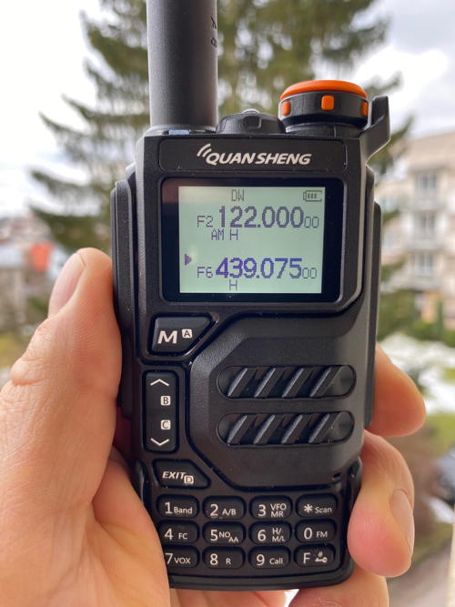
Another new toy, a Quansheng UK-K5(8). Size-wise it’s taller and heavier than the Baofeng UV5R and has a nicer display. The reason I got this, apart from the price is there is firmware available to enable a spectrum display among other things.

I’ve loaded this version: https://github.com/egzumer/uv-k5-firmware-custom/wiki. Loading was simple enough. There have been mentions that one needs to insert the programming cable very firmly but I found that my aftermarket Baofeng USB cable went in quite easily with a click. Once I had remembered you need to turn the radio on in program mode the firmware went in via the Edge browser in just a few seconds.

Other than that I have yet to use it on air and it has not yet been near a spectrum analyser so no idea how good or bad it is RF wise. There’s plenty of information out there already anyway. For me, like the UV5R it’s a handy little radio that won’t hurt too much if lost or damaged, but it is the available firmware that seals the deal.

Amateur radio in the news: Hackable ham radio, ham radio at the museum, club hosts Scouts

By: Dan KB6NU
5 April 2024 at 13:38

The Most Hackable Handheld Ham Radio Yet

The [Quansheng] UV-K5, released last year, might be the most hackable handheld ever, with a small army of dedicated hams adding a raft of software-based improvements and new features. I had to have one, and $30 later, I did.

Like Baofeng’s 5R, Quansheng’s K5 as a radio transceiver is fine. (I’m using K5 here to refer to both the original K5 and the new K5(8) model.) The key technical distinction between the 5R and K5 is a seemingly minor design choice. With Baofeng’s 5R, the firmware resides in read-only memory. But Quansheng stores the K5’s firmware in flash memory and made it possible to rewrite that memory with the same USB programming cable used to assign frequencies to preset channels.

…read more


ICHMS collaborates with IRARC

CASPIAN, MI – The Iron County Historical & Museum Society (ICHMS) will have two new exhibits this summer thanks to a collaboration with the Iron Range Amateur Radio Club (IRARC) and a grant from the Crystal Falls/Dickinson Area Community Foundation. “We couldn’t be any more excited about this collaboration and the exhibits that will come from it”, states museum director Kathlene Long. The club members are in here helping build the exhibits and are bringing their expertise along with their own artifacts to build these exhibits in time for this coming summer season.

Railroad depot building
The Stager Depot at the Iron County Historical Museum in Caspian, MI.

The Club is building a working ham radio station in the museum. It will be fully functional. Museum visitors will be able to see the exhibit and signs will help visitors understand the importance ham radios – and amateur operators – have played in our county’s, and our country’s history. They will also learn why they continue to be so important. In addition, the Club is recreating a display of a vintage WIKB studio from pieces they have collected over the years. All of this is being paid for, in part, from a $500 grant from the Crystal Falls/Dickinson Area Community Foundation. “All in all, this is a lot of moving parts finally coming together to make this happen.” Long explains.

…read more


SIERA hosts Scout amateur radio merit badge day

METROPOLIS, IL — Boy Scouts talked to amateur radio operators as far away as Puerto Rico and Arizona during a radio merit badge class hosted by the Southernmost Illinois Emergency Radio Association (SIERA). Five scouts from Troop 2007, out of St. Thomas More Catholic Church in Paducah, attended the class on Saturday, March 23, at Trinity Church in Metropolis.

Scouts experimented with tuning forks and a wave generator and had the opportunity to talk on both handy-talkie and high-frequency base radios during the class. They also learned about the science and mechanics of radio as well as important safety measures.

…read more


About UV-K5 CEC Firmware Version 0.1X (from v0.1p)

 About UV-K5 CEC Firmware Version 0.1X (from v0.1p)


1.About Version 0.1X

This version is the stable version of UV-K5 Version 0.1P

In Version 0.1P, many things were changed, including the internal variable structure, and we received feedback for about 8 days to check if there were any problems. The original plan was to just change the name from Version 0.1P to Version 0.1X, but several features were added as follows. Please read Version 0.1P for main features


2.SSB Filter (bandwidth)

  The filter can select one of these : VFO, 3K, 2K, 1.7K, 3K+, 2K+,1.7K+  

  This filter operates only in SSB mode and is disabled in existing FM mode.  If you select a filter with +, the + mode is also applied to CW mode


  VFO : Previous firmware state. It is selected among WIDE/NARROW selected in VFO


 3K ~ 1.7K : When actually measured, it is a little wider than stated.


3K+ ~ 1.7K+ : It improves the functionality of the existing filter. Based on SINAD, there is an improvement effect of about 1dB.


3.SSTV 

3.1 Scottie 1 Mode 

Scottie1 mode was added to the existing Martin1 mode. You can select it from STVEnc in the settings menu.


3.2 TX Screen preview
Shows which screen is being transmitted.


3.3 QSO TX Number

  SSTV transmission sequence record. It is displayed at the top right when transmitting SSTV.


3.4 SSTV transmission resolution has been increased. If this causes problems, I plan to reduce the resolution again.

X-TAL is not connected to the MCU (CPU) used in UV-K5. (Internal LC res) So, there is a slight problem during precise transmission like SSTV.


4. Download 

https://github.com/phdlee/uvk5cec/releases/tag/v_0.1x

Modification of SI4732-A10 for full HF band reception on UV-K5

 Modification of SI4732-A10 for full HF band reception on UV-K5


I will guide you on applying SI4732-A10, which is mainly used in shortwave radios that support SSB, to UV-K5.   Firmware Version CEC_0.1HF
  1. This version is different from the existing CEC series of UV-K5
  2. This version is a test version for devices in which the FM radio chip BK1080 of the UV-K5 radio has been removed and replaced with SI4732-A10.
  3. Do not upload to your radio if you have not modified the hardware
  4. When the source of UV-K5 CEC version is released (Release 1.0), you will be able to run SI4732-A10 through Makefile options


1. Parts

  1.1 SI4732-A10 * 1

If you search SI4732-A10 on Google, you will find various shortwave receivers. It has been popular with many people for several years due to its pretty good performance.

You can buy it on aliexpress for about $2.xx 

There are several versions of SI4732, but the one that supports SSB is the one with A10. You must purchase SI4732-A10

  1.2 X-tal 32.768Khz  * 1

  1.3 Capacitor 15~35pF * 2 (When purchasing crystal, purchase it in the recommended dosage. Approximately 22pF works in most cases)

  1.4 Capcitor 100uF * 1 (or 50uF ~ 200uF)

  1.5 Registor 10~15K * 1

2.circuit diagram

  The red numbers shown in the circuit diagram below are the pin numbers for the existing BK1080.

In the circuit below, the letters 3 and 4 mean to connect to both numbers 3 and 4

To use FM radio, you must connect a separate antenna. However, even if you only use AMI, you can hear a strong FM signal well. (If you want to improve FM radio performance, you must implement and connect a separate antenna or SPLITTER)


I wrote numbers on the PCB board below.
If you feel the sound is low, connect to POINT.A instead of 3 or 4.


3.Tip
It is difficult to make it in a general PCB form due to lack of space.
I stuck the SI4732-A10 upside down on double-sided tape and soldered the parts.
Before attaching, make sure the lid closes well before connecting.
If you can replace your existing speakers with smaller ones, you can use a regular PCB.

4.operate

A representative product of SI-4732 is the ATS-20 in the picture below. I created the firmware by referring to the ATS-20's screen interface.


Buttons 
  Number 0 : Long Press -> Enter SI4732-A10 Mode 
  Exit          : Long Press -> Exit SI4732-A10 Mode

  UP / DOWN : Frequency Up or Down (Step)
  Side Button : Frequency 1Mhz Up or Down
  Number 1 : Change Bandwidth (use LSB or USB mode)
  Number 4, Number 7 : BFO Frequency Up/Down,  This function allows adjustment in Hz units in SSB mode.
  Number 2 : AGC ON/Off
  Number 5 : Att Manual Mode (AGC Off) and Att change
  Star (*)     : Step Change  (1 -> 5 -> 10 -> 20 -> 50)
  F (Function): Short Press : change mode AM <-> FM or LSB <-> USB 
                   Long Press : AM/FM   -> LSB/USB or LSB/USB -> AM/FM


5.Download
  

6.More Information
 6.1 Using Library source  (my work is below code ported UV-K5, C++ to C and more)


 6.2 Circuit diagram related to FM radio of UV-K5
 
I did the SI4732 MOD a few months ago. At the time, I didn't have a circuit diagram, so I checked it by scraping the pattern on the board with a cutter knife, and a grateful radio amateur (IU0AZB)sent it to me last night.

If you want to improve reception performance, you can try changing the boxed areas below.
In particular, simply removing all the parts in the red B square will slightly improve reception performance.
A few years ago, I made a receiver with the SI4735, a model similar to the SI4732-A10, and due to the characteristics of the radio chip, I used a transformer to increase the impedance. I experienced a tremendous improvement in reception performance. However, interference waves are also quite strong, so a filter (FMI, AMI) must be used.

The space where we work is small. I hope that the various experiments of amateur radio operators will yield good results.

6.3 TODO : Removing the crystal and two capacitors
We are examining whether three components can be removed by using an external clock (BK4819's reference clock - Checked by IU0AZB)
I experimented a few times, but it didn't work. I suspect an interference problem due to the reset circuit, which is different from the original circuit and is configured as analog, or my experimental environment.
If successful, only SI4732 and two components (C1, R1) are needed.


DE KD8CEC


Introducing UV-K5 Version 0.1P (CW)


Introducing UV-K5 Version 0.1P (CW Mode)

CW-related functions have been added to version 0.1P. The spectrum function has been removed but is maintained in the source code. Later, when the source code is distributed, you can activate it and use it if necessary. This version is for testing purposes only. It will be redistributed as the stable version 0.2 in approximately 1-2 weeks. If you don't want to beta test, you can wait a week or two and download 0.2
1.Caution - Please read
  1.1 The CW mode added in this version is identical to the actual CW function used in general shortwave radios. In some countries, CW communication may require another license. Check whether CW operation is available in your country
The CWF mode added in this version is FM-based CW. If you have a license that does not allow you to operate CW, CWF may be possible. 

  1.2 If you use an external key, you must set up CW AD1, CW AD2, CW AD3, and CW AD4. If this value is set too low, CW will continue to be transmitted and the this firmware (support CW) will become unusable.  To prevent that, if CW is transmitted within 4 seconds after turning on the radio (PTT, external key, or whatever), I stop the CW and switch to FM mode. If you do not press PTT or an external keyer within 4 seconds of turning on the radio, but the UV-K5 beeps 10 times and automatically switches to FM mode, check the values of CW AD1 to CW AD4.


2.How to connect CW key
  Connect to the 3.5mm jack of UV-K5 as shown below.
  If you use 10K and 20K resistors and your CW key contacts are clean, you will probably be able to use it right away without needing to set up CW AD1, CW AD2, CW AD3, and CW AD4.

If you do not have 10K and 20K resistors, you can find resistors from 20K to 3K with a difference of about 2 and connect them. However, in that case, the 'CW AD' value will have to be adjusted quite difficult.  I recommend using 10K or 20K resistors. The reason I chose 10K and 20K resistors is because they are easy to find nearby.
(PADDLE KEY)


(STRAIGHT KEY)


I implemented the CAT communication introduced in the video a few weeks ago on UV-K5. (Not included in this version) The picture below is the configuration used in the video.
Using this, I implemented 'Win Keyer' and 'Nano Keyer', which are often used by DX'er, on UV-K5.  I am wondering whether such a function is necessary for a portable radio.
And there is no doubt that both 'Win Keyer' and 'Nano Keyer' are very enchanting keyers. But I have to choose one of them. If it is included in the next version, you can connect it by referring to the circuit below.


3.Mode Description
Three modes have been added in this version. 
The original plan was to include CWR, but it was not included because users would be confused by too many modes.  However, in the UV-K5, which receives both the upper and lower sides centered on the BFO (In reality, BFO is not used and operates by calculation), I continue to think that I need CWR to know the exact location of the CW I am listening to.
So maybe CWR may be added in the future.

  3.1 CW Mode
      This is the CW mode we know. It is transmitted as A1A without any special modification.  ‘CW’ is displayed on the screen.

  3.2 CWF Mode
      This is how CW sound is transmitted in FM mode (F2A). Unlike CW mode, when in CW TX mode, radio waves are being transmitted immediately. Pressing the CW keyer only adds sound. 'CWF' is displayed on the screen and reception is performed in FM mode. Same as FM mode.

  3.3 CWN Mode
      Same as CW mode, but not transmitted. You can use it for practice.
     It will appear on the screen as 'CWN'.


4. Keyer
  You can select from ‘CW KEY’ in the setup menu.
  4.1 K-ST : This is a straight key used as a keypad. (PTT or M)
  4.2 K-PD : This is a paddle key used as a keypad. (PTT and M)
     M : DAH
     PTT : DIH
    It operates in IAMBIC.A style.


  4.3 E-ST : This is external straight Key using 3.5mm connector
  4.4 E-PD :This is external paddle Key using 3.5mm connector 
      It operates in IAMBIC.A style.

  4.5 PC  : Not supported yet.
    If UV-K5 has a built-in WinKeyer or NanoKeyer, it can be used by connecting to a computer.


5. How to use CW Mode
 CW mode only works when the radio's mode is 'CW', 'CWF', or 'CWN'.
  You can enter CW transmission mode in two ways.


5.1 Manual Start CW TX
   The first is to press PTT once. In this case, CW TX mode is maintained until the 'Exit 'button is pressed. When you finish transmitting CW, be sure to press the Exit button to return to receiving mode. If the 'Exit' button response is delayed, it is not an error. When transmitting with the paddle key, the idle time may be maintained after transmission.

5.2 Auto Start CW TX
  The second is automatic mode using the paddle keys. If you use external paddle keys or straight keys, press the key once. It automatically switches to CW TX mode. At this time, the pressed CW Key is not transmitted via radio waves. In this case, when CW transmission ends, it automatically switches to reception mode.
The time for CW transmission to end and switch to reception mode can be set in 'CW DLY' in the set up menu.

6. How to use Memory Keyer
  The picture below shows the basic CW mode.  This is the screen that appears when switching to CW TX mode.


Below are the CW functions used in basic mode. 
Please refer to the video for how to use.


Pressing the * (STAR) button in basic mode switches to CW MSG transmission mode. Press the * button again to return to basic mode. In Advanced mode, you can check the DX CALL stored in the radio.


In the Advanced menu, the role of the numeric keypad changes to the 'CW MSG' transmission shortcut key.

Please refer to the video for how to use.

7.Download
As announced in advance, various experimental versions will be released up to V1.0, and the source code will be registered when V1.0 is released. Until V1.0, we will only upload firmware binary files. (This version release includes version 0.1C source code)
You can update it using cec_0.1p.packed.bin


DE KD8CEC

Introducing UV-K5 Version 0.1M (SSTV, Text Configuration)

 Introducing UV-K5 Version 0.1M (SSTV, Text Configuration)

In version 0.1M, items related to text settings and SSTV transmission function were added. As previously announced, only compiled binaries will be released from 0.1M until 1.0 is released.When the version is upgraded to 1.0, we will organize the source code and release it together. It probably won't take long.


1.Improved text input

   Most of the contents are the same as the existing firmware. I only did something very small.  Since you will be using text input frequently in the firmware (UV-K5 CEC version), changed it to make input more convenient. I only changed the function of the * button and the F button very slightly.


Once you select a letter, press the 'M' button to move to the next step. If you enter something incorrectly, you can press * to go back.
Press 'F' to change the input to uppercase, lowercase, _ (do not enter), or Space
For example, when you want to input the capital letter 'C', press the 'F' key to make it 'A', then press the UP KEY twice to make 'C' appear, then press the 'M' button to move to the right

2.Text settings
The available channels have been reduced from 200 to 170, I needed some text related settings and decided to use the channel name fields from channel 171 to channel 200

It will remain compatible with other firmware. If you delete my firmware and install another firmware, only the channel name will be changed

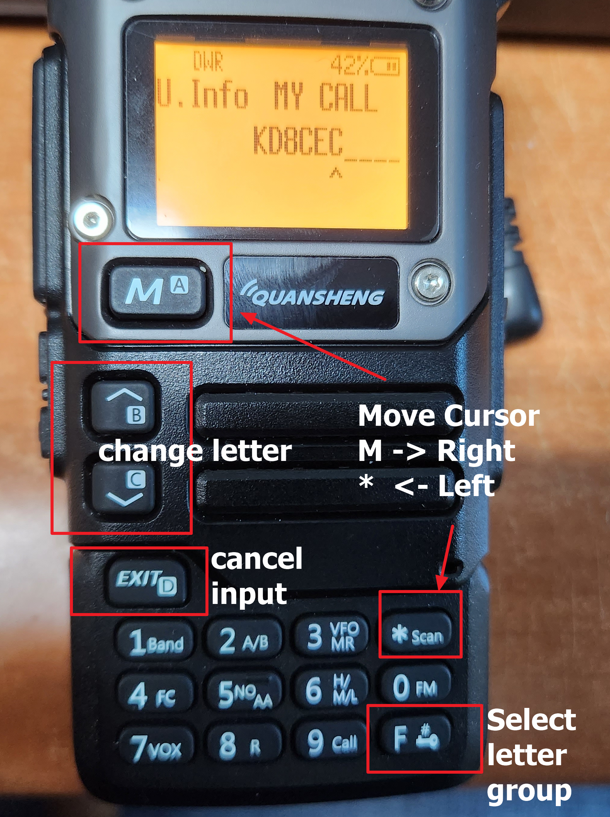
U.Info - > My Call : your call sign

U.Info - > My Name : your name

U.Info - > My Grid : your grid (using https://www.qrz.com/gridmapper)

           You only need to enter 4 digits (Example : EM37)

U.Info - > DX Call : Call sign of the other party (This is used on SSTV and CW Eleckeyer)

U.Info - > DX Name : Name of the other party (This is used on SSTV and CW Eleckeyer)


And there are a few additional text items (CW message, GPS Location and etc). Enter whatever you want to enter.


3.SSTV transmission function


SSTV supports Martin v1. Due to limitations in flash memory space for writing firmware, various functions could not be included. However, I am also considering adding the ability for SSTV users to create their own templates if they wish.

(The implementation included scottie and PD90 protocols, but they were excluded when compiling due to lack of firmware space)


The text to be included in the picture must be entered in SSTV M1 (SSTV message 1) in the text input menu (U.Info).


Please enter your message on M2 as well. Usually, it is good to input the signal status of the other station. 


Enter the T.SSTV menu.

Press the 'M' button to select CQ.
And if you press it again, SSTV will be transmitted

When transmitting a QSO, the call sign of the other station is displayed. In the text input menu, enter the call sign of the other station in advance in the DX CALL item.

The LCD menu is just for a bit of fun. When you press this button, it is transmitted as a radio wave to the screen of your UV-K5 10 seconds later. Of course, your call sign will be overlaid on the screen

I have ported a few games to UV-K5 and will release them later when I have the chance. It might be fun to transmit your Tetris screen and scores to SSTV. LOL

Additional: I thought a lot about resolution when transmitting SSTV. If this is not a toy but a function that is actually used, I thought it should have a resolution that can be read when transmitted with a 5W radio rather than being flashy.


4.Download Link

https://github.com/phdlee/uvk5cec/releases/tag/v_0.1m


5. Video (How to)


DE KD8CEC


❌
❌