Smart Edition Bluetooth LiFePO4 battery – Charge Controller | Power Queen
3 June 2024 at 18:15
Power Queen Bluetooth Smart Edition LiFePO4 battery and charge controller test.

Heading out for some portable operations yesterday, I had a few objectives in mind. First, I needed to take some pictures of an antenna mount for an article I’m working on. I also wanted to do a POTA activation, while also making some Winter Field Day (WFD) contacts. Lastly, I wanted to try out an inexpensive LiFePO4 battery I recently purchased.
I planned to do all this stuff while at Ridley Creek State Park (K-1414, KFF-1414). I started off by setting up to take the pictures for the article. After getting the shots I needed, I set up to get on the air. Today, I was using my KX3 (5 watts CW) and 12-foot loaded whip. I also had a 29-foot vertical wire fed through a 9:1 unun.
I finished setting up about 10 minutes before WFD kicked off, so I started calling “CQ POTA” on 30M. By the time WFD started, I had the required 10 POTA contacts in the log. After marking myself as “QRT” on the POTA spotting page, I started “searching and pouncing” on the bands. I was hunting for WFD, POTA, or anything else that seemed interesting.
After a little under two hours, I wrapped up with 25 contacts in my log. Thirteen of them were WFD contacts. I also had a park-to-park QSO with AA4XX down in North Carolina. It’s always a pleasure to work Paul. A Straight Key Century Club contact with K3Y/8 rounded out my log.
The battery I was using today was a 6 Ah LiFePO4 battery I found on Amazon for about $20 (US). My trusty Bioenno batteries are still hanging tough after more than six years of use, but I was curious to see how this cheap battery would work. It did just fine, but we’ll see how it holds up over time.
With some welcomed mild weather yesterday, this wasn’t the most wintry of Winter Field Days here in Pennsylvania. I wish I had more time for it this weekend, but life had other plans for me. Best of luck to everyone taking part in WFD.
73, Craig WB3GCK
![]()
Nothing is sacred, including batteries. Do you have concerns about technology intruding on your life and privacy? We have reached a point where even batteries —yes, batteries— are documented and recorded. What am I talking about? You may have never heard of a digital battery passport (DBP), but pay attention... Read more »
The post Digital Battery Passport: Be Aware, Not Afraid. appeared first on Off Grid Ham.
Over time, my POTA activation kit has grown smaller, due in no small part to a reduction in battery size. I’ve transitioned from a 60AH, to 30AH, and finally a 15AH Lithium Iron Phosphate (LiFePO4) battery. Understanding the power requirements of my activation radio after 50+ outings has allowed me to activate with confidence that I won’t run out of power.
With an understanding that Rhode Island is fairly rare, my activations almost always generate a pile-up, and maintaining a rate of 1 contact per minute (60 an hour) is easy to do. At this point I plan on the following:
Yep, CW takes more power on average!
Since LiFePO4 batteries allow you to safely consume in excess of 90% of their rated capacity before the battery voltage tails off significantly, that pretty much says I can have about 2.5 hours of heavy operating time using a 15 AH battery. In my world, that corresponds to 2 parks between charges. Using that rule of thumb, I’ve never run out of power in the field, and I’ve done as many as 4 shorter 30 minute activations in a single day.
I do carry a smaller 9 AH battery as a “backup”, but I’ve only used it once in 50+ activations (and that was because my primary battery failed).
A classic never goes out of style. Way back in 2016 I posted the Off Grid Ham 100 Watts for $300 Solar Plant. Even today, that article is still hugely popular and one of the most viewed posts on this website. In a 2020 update, the $300 threshold not only... Read more »
The post The Off Grid Ham 100 Watts For $300 Solar Project -2023 Update appeared first on Off Grid Ham.
A viewer recently sent me a message about batteries and what type of battery that I use for my portable operation. That’s a big question as I’m currently using three different batteries depending on the situation. But they all share a common trait, so let’s dig into battery power.
When I started operating portable many years ago, batteries were heavy and had limited power capability. A common battery, like this 30 amp hour lead acid AGM battery would give you a few hours of operation time before its capacity would drop to a point you would have to put it on a charger. Lithium technology was new and expensive, so we suffered with these inefficient, heavy batteries out in the field.
Fast forward a few years and not only is an equivalent Lithium Iron Phosphate battery cheaper than a lead acid battery, but it also has a longer service life, making the total cost of ownership even cheaper.
TalentCell 12V LiFePO4 Battery: https://amzn.to/3YebKlm
ECO-WORTHY 12V 20Ah Lithium Battery: https://amzn.to/4507NCN
Renogy 12V 50Ah LiFePO4 Lithium Battery: https://amzn.to/3Ortzdl
lifepo4 charger 15-Amp Fully-Automatic Smart Charger: https://amzn.to/3KgOldk
High Precision Watt Meter Voltage Amp Meter Power: https://amzn.to/44WJcyQ
Now there are certain cases where a lead acid battery is a better choice, but for casual portable operating those exceptions dont’ come into play and you will benefit with using a lithium battery.
In this video, when I say lithium battery, I mean Lithium Iron Phosphate. There are many types of lithium batteries with different chemistries. Lithium iron phosphate is most common in ham radio circles as they are much safer than other forms of lithium cells. I’ll talk about the safety features in a bit.
So why lithium iron phosphate and not lead acid batteries? There are two main reasons. The first is the size and weight. The main component of a lead acid battery is, you guessed it, lead. These batteries are heavy. Approximately 3 to 5 times as heavy as an equivalent lithium battery. If you’ve had to carry a battery for any appreciable distance, you know you don’t want it to be a lead acid battery.
The second point is energy density. That’s the amount of power a battery is capable of holding. A lead acid battery can hold about 30-50 watt hours per kilogram of weight, while a lithium iron phosphate battery is on the line of 90-120 watt hours per kilogram. Related to this energy density, a lead acid battery can only be discharged to about 50 percent of it’s capacity before it needs to be recharged, otherwise damage to the cells can occur. Lithium iron phosphate batteries can go down to 80 to 90 percent of capacity, so they can deliver more energy for a longer period of time.
Also important to consider about lithium iron phosphate batteries are their safety features. Now of course any battery is dangerous in that it can hold a large amount of power, so like anything electric, treat it with respect. But the lithium iron phosphate chemistry is intrinsically safer and won’t catch on fire or explode from overcharging like other lithium batteries. These batteries also have a battery management system, or BMS to regulate the charge input and output of the battery. The BMS will make sure you don’t overcharge the battery and it will prevent you from depleting the battery down to 0 percent. The BMS will also help prevent you from drawing more current than what the cells will allow. They also provide other load balancing and cell management functions, so they are an important part of the operation of the battery.
I have three different batteries that I use with my FT-891. All of them are Lithium Iron Phosphate (LiFePO4). I started out with a 12 ah battery. At 50 watts transmit power SSB I can usually get about 2.5 hours with it.
A couple years ago, I bought a little bigger 20ah battery. I like this one a lot as it will last all weekend if I use it exclusively for phone operation, with digital or a mixture of phone and digital, it will last for an afternoon, about 3-5 hours.
In my camping trailer I had a 50ah battery, but last year I upgraded that to a 100 ah battery. With the bigger battery in the trailer I can run the refrigerator all weekend even if we are in a shaded campsite. Since I started doing more digital operation, I started to bring the 50ah battery with me on the longer outings. This will last all weekend with phone and heavy digital operation. This is also the battery I’ll grab if I’m running mobile or portable for a QSO party as I know I won’t run out of power.
With the exception of the camping trailer, which has full time solar charging, I don’t bring solar panels out in the field to charge the radio batteries. I find that it’s easier to carry a bigger battery with me than to set up a solar panel and try to move it every hour or so to catch the sun. I just pick an appropriate sized battery for the duration I’m going to operate and when I’m done, I’m done.
My favorite battery is the Eco-Worthy 20 ah LiFePO4 battery. It has really held up well the last two years and it is dirt cheap online: https://amzn.to/44oOfYV
But the biggest question I get is, how large of a battery do I need? The answer depends on two things: how long will you be on the air, and what will your transmit power be. These both factor into your overall energy budget. For QRP operation, 10 watts or less, you can get by with very small lightweight batteries. If you want to transmit at 100 watts, you are going to need a battery that will cover that amount of current draw. If you are primarily phone operation, you can get by with a little smaller battery, and if you are running full duty cycle, like many of the digital mode do, then you will need more battery capacity.
A battery isn’t going to provide more than its rated capacity. If the battery says 20 amp hours, for the most part it will provide up to 20 amps of current. You’ll be able to run100 watts of phone on a 20 amp hour battery because the efficiency of a sideband signal will seldom get you to that 20 amp limit. But a 12 amp hour battery will limit the current output, cutting your transmit power.
The post Picking the best battery for portable Ham Radio appeared first on KB9VBR Antennas.
When you want to expand your battery capacity. Off grid ham radio has an addictive quality about it. You tell yourself, “I’ll get a modest battery and solar panel and just fool around a little bit. I’m not too serious about this,” thinking that’s as far as you’ll ever go.... Read more »
The post Battery Isolators, Separators, and Combiners. appeared first on Off Grid Ham.
Graduation time. A lot of if not most off grid hams have only one battery in their system. Connecting a single battery is more or less self-explanatory. What should you do when you expand your system to include multiple batteries? Should they be in series? In parallel? Is one way... Read more »
The post Series and Parallel Battery Connection Techniques. appeared first on Off Grid Ham.
It cannot be avoided… Batteries are arguably the weakest link in the off grid radio chain. Solar panels, controllers, connecting cables, and almost everything else can last years, even decades. But batteries are a consumable product and no matter how good yours are, it’s almost certain they will not last... Read more »
The post Batteries: Your Weakest Link. appeared first on Off Grid Ham.
A blog posting about a fan? Really?
Why not!
 |
| Figure 1: The modified fan on my cluttered workbench, running from 13 volts. The external DC input plug is visible on the lower left. Click on the image for a larger version. |
This blog post is less about a fan, but is more of example of the use of a low-cost buck-type voltage converter to efficiently power a device intended for a lower voltage than might be available - in this case, a device (the fan) that expects 3 volts. In many cases, "12" volts (which may be anything from 10 to 15 volts) will be available from an existing power source (battery, vehicle, power supply) and it would be nice to be able to run everything from that one power bus.
Background
Several years ago I picked up a 5" battery-operated DC fan branded "O2 Cool" that has come in handy occasionally when I needed a bit of airflow on a hot day. While self-contained, using two "D" cells - it can't run from a common external power source such as 12 volts.
Getting 3 volts
Since this fan uses 3 volts, an obvious means of powering it from 12 volts would be to simply add a dropping resistor - but I wasn't really a fan of this idea (pun intended!) as it would be very wasteful in power and since doing this would effectively defeat the speed switch - which, itself is just a 2.2 ohm resistor placed in series with the battery when set to "low".
The problem is that the fan itself pulls 300-400 mA on high speed. If I were to drop the voltage resistively from 12 volts (e.g. a 9 volt drop) - and if we assume a 300mA current - we would need to add (9/0.3 = ) 30 ohms of series resistance to attain the same speed on "high" as with the battery. The "low speed" switch inserts a 2.2 ohm resistor, and while this works with its original 3 volt supply, adding this amount to 30 ohms would result in a barely noticeable difference in speed, effectively turning it into a single-speed fan. By directly supplying the fan with something close to the original voltage, we preserve the efficacy of the high/low speed switch.
Fortunately, there's an answer: An inexpensive buck converter board. The board that I picked - based on the MP1584 chip - is plentiful on both EvilBay and Amazon, typically for less than US$2 each. These operate at a switching frequency of about 1 MHz and aren't terribly prone to cause radio interference, having also been used to power 5 volt radios and even single-board computers (such as the Raspberry Pi) from 12 volts without issues.
These buck converters can handle as much as 24 volts on the input and provide up to 3 amps output - more than enough for our purpose - and can also be adjusted to output about any voltage that is at least 4 volts lower than the input voltage - including the nominal 3 volts that we need for the fan.
An additional advantage is the efficiency of this voltage conversion. These devices are typically 80% efficient or better meaning that our 300 mA at 3 volts (about 0.9 watts of power) would translate to less than 100mA at 12 volts (a bit more than a watt). Contrast this to the hypothetical resistive dropper discussed earlier where we would be burning up nearly 3 watts in the 30 ohm resistor by itself!
Implementation
One of my goals was to retain the ability of this fan to run at 3 volts as it would still be convenient to have this thing run stand-alone from internal power. Perhaps overkill, but to do this I implemented a simple circuit using a small relay to switch to the buck converter when external power was present and internal power when it was not, rather than parallel the buck converter across the battery.
If I never intended to use the internal "D" cells ever again I would have dispensed with the relay entirely and not needed to make the slight modifications to the switch board mentioned below. In this case I would have had plenty of room in the case and freedom to place the components wherever I wished. In lieu of the ballast of the battery to hold the fan down and stable, I would have placed some weight in the case (some bolts, nuts, random hardware, rocks) to prevent it from tipping over.
The diagram of this circuitry is shown below:
 |
| Figure 2: Diagram of the finished/modified fan. On the left, J1 is the center-positive coaxial power connector with diode D1 and self-resetting resetting thermal fuse F1 to protect against reverse polarity. The relay selects the source of power. Click on the image for a larger version. |
The original parts of are the High/Low switch, the battery and the fan itself on the right side of the schematic with the added circuits being the jack (J1), the self-resetting fuse (F1), D1, R1, the buck converter and the relay (RLY).
How it works:
When no external power is applied, the relay (RLY) is de-energized and via the "NC" (Normally-Closed) contacts, the battery is connected to the High/Low switch and everything operates as it originally did.
External power is applied via "J1" which is a coaxial power jack, wiring the center pin as positive: The connector that I used happens to have a 2.5mm diameter center pin and expects an outer shell diameter of 5.5mm. There's nothing special about this jack except that I happen to have it on-hand.
When power is applied, the relay is energized and the high/low switch is disconnected from the battery but is now connected, via the "NO" (Normally Open) contacts, to the OUT+ terminal of the buck converter.
Ideally, a small 12 volt relay would be used, but the smallest relay that I found in my junk box was a 5 volt unit, requiring that the coil voltage be dropped. Measuring the relay coil's resistance as 160 ohms, I knew that it required about 30 mA (5/160 = 0.03) and if we were to use 12 volts, we'd need to drop (12 - 5 =) 7 volts. The resistance needed to drop 7 volts is therefore (7/0.03 = ) 233 ohms - but since I was more likely to operate it from closer to 13 volts much of the time I chose the next higher standard value of resistance, 270 ohms to put in series for R1.
 |
| Figure 3: Modification of the switch board. The button is the positive battery terminal and traces are cut to isolate it to allow relay switching. Click on the image for a larger version. |
Modification to the switch board
The High/Low switch board also houses the positive battery contact, but since it is required that we disconnect the battery when running from external power, a slight modification is required, so a few traces were cut and a jumper wire added to isolate the tab that connects to the positive end of the battery as seen in Figure 3.
 |
| Figure 4: The top of the board battery board. The connection to the Batt+ is made by soldering to the tab. Click on the image for a larger version. |
In Figure 4 we can see the top of the board with the 2.2 ohm resistor - but we also see the wire (white and green) that connects to one of the tabs for the Battery + button on the bottom of the board: The wire was connected on this side of the circuit board to keep it out of the way round battery tab and the "battery +" connection.
The mechanical parts
For a modification like this, there's no need to make a circuit board - or even use prototyping boards. Because we are cramming extra components in an existing box, we have to be a bit clever as to where we put things in that we have only limited choices.
 |
| Figure 5: Getting ready to install the connector after a session of drilling and filing. Click on the image for a larger version. |
Figure 5 shows the location of this connector. Inside the box. this is located between two bosses and there is just enough room to mount it. To do this, small holes were drilled into the case at the corners of the connector and a sharp pair of flush-cut diagonal nippers were used to open a hole. From here it was a matter of filing and checking until the dimensions of the hole afforded a snug fit of the connector.
 |
| Figure 6: A close-up of the buck converter board with the attached wires and BATT- spring terminal. The tiny voltage adjustment potentiometer is visible near the upper-left corner of the board. Click on the image for a larger version. |
Figure 6 shows the buck converter board itself in front of the cavity in which it will be placed, next to the negative battery "spring" connector. Diode D1 is soldered on the back side of this board and along the right edge, the yellow self-resetting fuse is visible. Like everything else the relay was wired with flying leads as well, with resistor R1 being placed at the relay for convenience.
 |
| Figure 7: The relay, wired up with the flying leads. Click on the image for a larger version. |
Figure 7 shows the wiring of the relay. Again, this was chosen for its size - but any SPDT relay that will fit in the gap and not interfere mechanically with the battery should do the job.
The red wire - connected to the resistor - comes from the positive connector on the jack and the "IN+" of the buck converter board - the orange wire is the common connection of the High/Low switch, the white/violet comes from the "OUT+" of the buck converter and goes to the N.O. (Normally Open) contact on the relay, the white/green goes to the N.C. (Normally Closed) relay contact and the black is the negative lead attached to the coil.
Everything in its place
Figure 8 shows the internals of the fan with the added circuitry. Shoe Goo was again employed to hold the buck converter board and the relay in place while the wires were carefully tucked into rails that look as though they were intended for this!
Now it was time to test it out: I connected a bench power supply to the coaxial connector and set the voltage of my external test power supply at 10 volts - enough to reliably pull in the relay - and set the fan to low speed. At this point I adjusted the (tiny!) potentiometer on the buck converter board for an output of 3.2 volts - about that which could be expected from a very fresh pair of "D" cells.
 |
| Figure 8: Everything wired and in its final locations. On the far left is the switch board. To the left of the hinge is the relay with the buck converter on the right side of the hinge. The jack and negative battery terminal is on the far right of the case. Click on the image for a larger version. |
The only thing left to do was to make a power cord to keep with the fan. As is my wont, I tend to use Anderson Power Pole connectors for my 12 volt connections and I did so here.
As I also tend to do, I always attach two sets of Anderson connectors to the end of my DC power cords - the idea being that I would not "hog" DC power connections and leave somewhere to plug something else in. While the power cord for the fan was just 22 gauge wire, I used heavier wire (#14 AWG) between the two Anderson connectors so that I could still run high-current devices.
* * *
Does it work?
Of course it does - it's a fan!
The relay switches over at about 8.5 volts making the useful voltage range via the external connector between 9 and 16 volts - perfect for use with an ostensibly "12 volt" system where the actual voltage can vary between 10 and 14 volts, depending on the battery chemistry and type.
 |
| Figure 9: The fan, folded up with power cord. The two connectors and short section of heavy conductor can be just seen. Click on the image for a larger version. |
Without the weight of the two "D" batteries, the balance of the fan is slightly precarious and prone to tip forward slightly, but this could be fixed by leaving batteries in the unit - but this is not desirable for long-term storage as leakage is the likely result.
Alternatively, one may place some ballast in the battery compartment (large bolt wrapped in insulation, a rag, paper towel, etc.) or simply by placing something (perhaps a rock or two) on the top. Alternatively, since the fan is typically placed on a desktop, it is often tilted slightly upwards and that offsets the center of gravity in our favor and this - plus the thrust from the airflow - prevents tipping.
This page stolen from ka7oei.blogspot.com
[End]
![]()
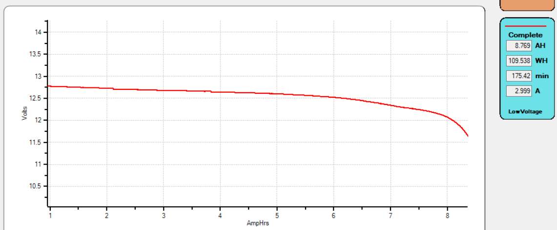
After reporting the failure of my Miady 16 AH battery (lightly used less than 3 years old), I dug out my “backup” battery: a 9.6 AH K2 Energy battery, purchased in mid 2011. That battery is 12 years old. It had not been recharged since December of 2021 (2.5 years ago).
I used my battery analyzer to do a simple constant current discharge and found the battery had a capacity of 8.7 AH, even after self-discharging for 2.5 years.
So there is clearly a difference between a quality LiFePO4 and a cheap one.
 |
| Figure 1: The completed "Word Metronome". There are two recessed buttons on the front and the lights on on the left side. Click on the image for a larger version. |
Thus, he asked me to make a "word metronome" - a stand-alone device that would provide a visual cue for speaking cadence. The idea wasn't to make the speech robotic and staccato in its nature, but rather providing a mental cue to provide pacing - something that is always a concern when trying to make a given amount of material fit in a specific time window: You don't want to go too fast - and you certainly don't want to be too slow and run over the desired time and, of course, you don't want to randomly change your rate of speech over time - unless there's a dramatic or context-sensitive reason to do so.
To be sure, there are likely phone apps to do this, but I tend to think of a phone as a general-purpose device, not super-well suited for most of the things done with it, so a purpose-built, simple-to-operate device with visual indicators on its side that could just sit on a shelf or desk (rather than a phone, which would have to be propped up) couldn't be beat in terms of ease-of-use.
Circuitry:
The schematic of the Word Metronome is depicted in Figure 2, below:
 |
| Figure 2: Schematic of the "Word Metronome" (As noted in the text, the LiIon "cell protection" board is not included in the drawing). Click on the image for a larger version. |
This device was built around the PIC16F688, a 14 pin device with a built-in oscillator. This oscillator isn't super-accurate - probably within +/-3% or so - but it's plenty good for this application.
One of the complications of this circuit is that of the LEDs: Of the five LEDs, three of them are of the silicon nitride "blue-green" type (which includes "white" LEDs) and the other two are high-brightness red and yellow - and this mix of LED types poses a problem: How does one maintain consistent brightness over varying voltage.
As seen in Figure 3, below, this unit is powered by a single lithium-ion cell, which can have a voltage ranging from 4.2 volts while on the charger to less than 3 volts when it is (mostly) discharged. What this means is that the range of voltage - at least for the silicon nitride types of LEDs - can range from "more than enough to light it" to "being so dim that you may need to strike a match to see if it's on". For the red and yellow LEDs, which need only a bit above two volts, this isn't quite the issue, but if one used a simple dropping resistor, the LED brightness would change dramatically over the range of voltages available from the battery during its discharge curve.
As one of the goals of this device was to have the LEDs be both of consistent brightness - and to be dimmable - a different approach was required - and this required several bits of circuity and a bit of attention to detail in the programming.
The Charge Pump:
Perhaps the most obvious feature of this circuit is the "Charge Pump". Popularized by the well-known ICL7660 and its many (many!) clones, this type of circuit may also be driven by a microcontroller and implemented using common parts. Like its hardware equivalent, it uses a "flying capacitor" to step up the voltage - specifically, that surrounding Q1 and Q2. In software - at a rate of several kHz - a pulse train is created, and its operation is thus:
It is by this method that we generate a voltage several volts higher than that of the battery voltage, and this gives us a bit of "headroom" in our control of the LED current - and thus the brightness.
Current limiter:
Transistors Q3 and Q4 form a very simple current limiter: In this case it is "upside-down" from the more familiar configuration as it uses PNP transistors - something that I did for no particular reason as the NPN configuration would have been just fine.
 |
| Figure 3: Inside the "Word Metronome". The 18650 LiIon cell is on the right - a cast-off from an old computer battery pack. The buttons on the board are in parallel with those on the case and were used during initial construction/debugging. Click on the image for a larger version. |
This circuit works by monitoring the voltage across R3: If this voltage exceeds the turn-on threshold of Q3 - around 0.6 volts - it will turn on, and when this does it pulls the base voltage, provided by R5, toward Q4's emitter, turning off Q3. By this action, the current will actually come to equilibrium at that which results in about 0.6 volts across R3 - and in this case, Ohm's law tells us that 0.6 volts across 47 ohms implies (0.6/47=0.0128 amps) around 13 milliamps: At room temperature, this current was measured to be a bit above 14 milliamps - very close to that predicted.
With this current being limited, the voltage of the power supply has very little effect on the current - in this case, that through the LEDs which means that it didn't matter whether the LED was of the 2 or 3 volt type, or the state-of-of charge of the battery: The most that could ever flow through an LED no matter what was 14 milliamps.
With the current fixed in this manner, brightness could be adjusted using PWM (Pulse Width Modulation) techniques. In this method, the duty cycle ("On" time) of the LED is varied to adjust the brightness. If the duty cycle is 100% (on all of the time) the LED will be at maximum brightness, but if the duty cycle is 50% (on half of the time) the LED will be at half-brightness - and so-on. Because the current is held constant, no matter what by the current limiter circuit, we know that the only think that affects brightness of the LED is the duty cycle.
LED multiplexing:
The final aspect of the LED drive circuitry is the fact that the LEDs are all connected in parallel, with transistors Q5-Q9 being used to turn them on. When wiring LEDs in parallel, one must make absolutely sure that each LED is of the exact-same type or else that with the lowest voltage will consume the most current.
In this case, we definitely do NOT have same-type of LEDs (they are ALL different from each other) which means that if we were to turn on two LEDs at once, it's likely that only one of them would illuminate: That would certainly be the case if, say, the red and blue LEDs would turn on: With the red's forward voltage being in the 2.5 volt area, the voltage would be too low for the green, blue or white to even light up.
What this means is that only ONE LED must be turned on at any given instant - but this is fine, considering how the LEDs are used. The red, yellow or green are intended to be on constantly to indicate the current beat rate (100, 130 or 160 BPM, respectively) with the blue LED being flashed to the beat (and the white LED flashing once-per-minute) - but by blanking the "rate" LED (red, yellow or green) LED when we want to flash the blue or white one, we avoid the problem altogether.
Battery charging:
Not shown in the schematic is the USB battery charging circuit. Implementing this was very easy: I just bought some LiIon charger boards from Amazon. These small circuit boards came with a small USB connector (visible in the video, below) and a chip that controlled both charging and "cell protection" - that is, they would disconnect the cell if the battery voltage got too low (below 2.5-2.7 volts) to protect it. Since its use is so straightforward - and covered by others - I'm only mentioning it in passing.
Software:
Because of its familiarity to me, I wrote the code for this device in C using the "PICC" compiler by CCS Computer Systems. As it is my practice, this code was written for the "bare metal" meaning that it interfaces directly with the PIC's built-in peripherals and porting it to other platforms would require a bit of work.
The unit is controlled via two pushbuttons, using the PIC's own pull-up resistors. One button primarily controls the rate while the other sets the brightness level between several steps, and pressing and holding the rate button will turn it off and on. When "off", the processor isn't really off, but rather the internal clock is switched to 31 kHz and the charge pump and LED drivers are turned off, reducing the operating current of the processor to a few microamps at most.
Built into the software, there is a timer that, if there is no button press within 90 minutes or so, will cause the unit to automatically power down. This "auto power off" feature is important as this device makes no noise and it would be very easy to accidentally leave it running.
Below is a short (wordless!) video showing the operation of the "Word Metronome" - enjoy!
This page stolen from ka7oei.blogspot.com
[END]
![]()