Update July 1, 2024. LoTW is back up! It is running slow, but it is available. Thank goodness.
--
When I wrote the article back in May, I hardly thought that LoTW would be down a month later.
Sadly, the outage continues.
My suspicions were correct, however, that this was something more than a simple networking problem. The ARRL has since admitted their network was viciously and uniquely hacked. I can certainly understand their caution to make sure that every system linked to LoTW is given a clean bill of health before turning the system back on.
Earlier this week, on Tuesday there was apparently a brief period of time when LoTW was accessible. A couple of my ham buddies managed to upload some contacts. They'll have to wait for confirmations when the rest of us can get in.
I do hope it is soon. I'm really missing this service.
Just over three years ago, I figured out how to Remotely operate FT8 using a product called RealVNC.
RealVNC had a Home plan that allowed up to 3 users and up to 5 devices for non-commercial use. Perfect for remotely controlled computers in a ham radio shack.
Today, without any notice, RealVNC disabled my Home plan, and I had to choose between paying each month for a plan, or adopting their Lite plan, which allows 1 user and up to 3 devices for non-commercial use.
That's fine. They allow me to use their secure remote access software without fees. I can understand they might want to change the terms.
The Lite plan fits my usage. I've only ever had two devices active anyway, and it's just me as the user.
But, without notice - that is just damned inconvenient. Since I switched plans, I need to visit each device and re-configure them to be part of the new plan. Which means I can't remote into those computers until that is completed.
FT8 has been a revolution. The technology has made DXing really easy. Or has it? I continue to be amazed at how much difficulty people have working DXpeditions on FT8.
Last year, there were DXpeditions to Bouvet (3Y0J), Crozet (FT8WW) and Sable Islands (CY0S). The most recent DXpedition to Glorioso Islands (FT4GL) has brought it all back to me.
Let's start off with a few observations on people trying to work these DXpeditions:
Wrong Cycle - It's amazing the number of folks trying to work DX that are calling on the wrong cycle. FT8 has even and odd cycles. Even cycles start at 00 or 30 seconds, and odd cycles start on 15 and 45 seconds. You always call on the cycle the DX station is NOT transmitting. Indeed, if you double-click on a decode of the DX station, WSJT-X will set up the correct cycle. So how are people getting it wrong?
Endless Calling - I've noticed some stations keep calling the DX after the DX station has QSYed or QRTed. A little bit of hopeful calling isn't unusual on Phone or CW, or even RTTY. But stations continue to call much later -- like an hour later, and they are still calling.
Calling without Response - Some stations don't respond when the DX station calls them. They keep calling instead of advancing to the next step. This can get really bad. During the FT8WW expedition, I saw FT8WW keep responding to the same station for more than 10 minutes. Each response had a different signal report. This made it clear that FT8WW was heading this caller quite well, but the caller wasn't hearing FT8WW at all. Instead, that station took up a valuable response slot for 10 minutes -- denying perhaps 20-40 stations from working FT8WW.
Confusing Fox/Hound (FH) and MSHV - Most DXpeditions using FT8 use either FH or MSHV in order to maximize the number of contacts they can make. It is easy to get confused with these two modes. They appear similar. Both allow for the DX station to transmit multiple FT8 carriers at the same time. FH imposes additional behavior to both the Fox and Hound ends of the contact. In particular, there are audio-frequency dependencies that FH enforces. But, it is perfectly possible to work a Fox station even if you are not in Hound mode. MSHV requires no special modes. And yet someone accused people of DQRM, calling FT4GL below 1000 Hz, when the DX was using MSHV, not FH.
What causes all these odd observations? I believe they all resolve to a single cause -- people are calling DX they cannot hear. That's right, people are calling DX stations they aren't decoding at all.
This is fundamentally wrong. I wrote about this years ago on how to bust a pileup. You cannot work DX if you cannot hear them. If you aren't decoding the DX station, stop calling. Yeah, that's hard, but your calls won't net you a contact, and you may be actively depriving someone who can hear the DX from making one.
I think FT8 has made some people lazy. They hear some DX station is active on some frequency, probably through a spotting network. So they switch to that frequency, set their watchdog timers to an hour or more, and enable their transmitter. Then they go off and drink a few cool 807s while their computer works the DX for them.
Farfetched? No, it explains all the observations above.
Be a good FT8 operator -- don't call DX when you cannot decode them. Wait until you can decode them reliably, just about every cycle -- then start calling.
May 16th, there was an issue with Logbook of The World (LoTW). I could not load the main page at all -- receiving an error indicating the server wasn't responding.
That's pretty normal stuff, actually. There are dozens of problems that can result in this kind of error, so I wasn't surprised. I figured the ARRL staff would address it quickly. But, after much of the day, I was still getting the error.
So, I sent a message to lotw-help@arrl.org, informing them that the web site wasn't responding, kindly asking when they expected it to be back up. I mentioned I was surprised there was no notice of the outage on the ARRL.org web site.
Later that day, the ARRL put up a notice that there was a service disruption involving access to the network, and that it affected LoTW and the ARRL Learning Center. They even updated it the next day, addressing concerns users had over information privacy.
But then, nothing happened. Not until May 22nd, when they updated the notice without really adding any information.
Now, part of this delay may be due to the fact that much of the ARRL staff were all out at the Xenia Hamvention. But, that was a week ago.
What gives? Sure, networking problems. Honestly, though, as a computer professional, networking problems generally don't take more than a week to solve. I'm beginning to suspect there's something more than the ARRL hasn't told us, but I can't be sure.
I'm really missing access to LoTW. In the last 20 years, it has really become central in my enjoyment of the hobby. I do hope I'm wrong, and that ARRL manages to fix this problem soon.
A50-3S standing tall and straight next to the house.
Last year, I moved the A50-3S out of the yard and up next to the house. I used a 19 foot mast made of two pieces of EMT. While putting it up the reflector bumped against the roof and turned askew about 15 degrees.
Never the less, it worked well. I worked a few Europeans and several South and Central American using this antenna.
Still, it needed a bit of work. A one-piece mast would be better, and I could straighten out the reflector when I swapped masts. A bead balun at the feed point wouldn't hurt either.
So, I researched these. You would not believe what a 20 foot piece of 1 1/2" 0.058 wall aluminum tubing goes for these days. A few years ago, I purchased a 12 foot piece of 2" diameter 1/4" wall 6061-T6 tubing for my gin pole. It was about $150, which seems right for such a substantial piece of metal.
But 20 feet of the thinner mast? They quoted me $500! If I went with the 1/4" wall, well that was manufactured with a different process -- extruded instead of rolled, so it would be $250. Ridiculous. There had to be another solution.
I did have 20 feet of mast in two 10 foot pieces. This was from an earlier experiment. I had an old Butternut HF4B that I had rebuilt, and was hoping to erect in Fulton County. I bought two pieces of Rigid Metal Conduit (RMC) for this purpose.
EMT and RMC are easily found at your local Home Depot. But it isn't exactly what you would call structural. EMT is design to bend. Easily. I have had some success using it as masting for very small, light antennas. The two pieces I used on the A50-3S lasted for over eight years, plus the several years holding up a 19 element 2m boomer Yagi. RMC is more substantial, and comes with threaded couplings to connect them together.
Two pieces of 10 foot RMC was $30 a pop, so this wasn't a cheap experiment. Even with the coupling tightened all the way down, the 20 feet of mast had a substantial wobble in the top section. I tried inserting a solid piece of HDPE. That helped, but not enough to hold up the HF4B.
It occurred to me that this might work with the A50-3S, even with the wobble. The A50-3S is held upright by a wall bracket at the eve of the house, well above the wobbly union. I just needed the vertical support, and not so much lateral rigidity. Besides, I already had $60 invested.
First order of business was to find the doggone things. I put them away three parsonage moves ago, and had hidden them well. They were hiding in my basement. After that, I had to locate the piece of HDPE, which I found in another box.
It all came together this week. My youngest daughter Lauren helped me to lower the existing A50-3S and mast to the ground. Off came the antenna and the feed line, and the old mast was disassembled and put away. Then I coupled the RMC together with the HDPE stiffener and taped the coupling joints against any water intrusion. With the A50-3S mounted on the new mast, the reflector was aligned with the rest of the elements.
For a balun, I used five snap-on ferrite beads. I measured these at about 100 ohms resistive at 50 MHz. Five conveniently fit on the 9913 coax from the driven element to the mast, so that is what I used.
A50-3S facing South East.
Swinging the new mast up into place without bashing the antenna against the house took some patience. The RMC mast is much heavier than the two pieces of EMT. Once vertical, I positioned the mast in the eve bracket and loosely connected the u-bolt clamp. Both my daughter and I lifted the assembly to the top of the railing. From there, I tightened the bracket to eliminate play, but loose enough to allow the antenna to rotate. I used a couple of extra 1/4" nuts as jam nuts so the bracket could not tighten or loosen.
The antenna is easily Armstrong rotated from the base. Eventually, I'll mount a rotator on the top of the railing and retire my arms.
A quick SWR check showed a 1.2:1 SWR at 50.313 MHz. The antenna is pretty broad. Minimum SWR is around 50.8 MHz at 1.07:1. I suppose I could mess with the matching network to get a better match on the FT8 frequency, but the whole bottom 2 MHz of 6m is less than 1.5:1.
The antenna is 28 feet (8.5m) off the ground with clear shots from the North clockwise to the South West. Points to the West and North West have to pass through the house roof.
I was QRV in Gordon county briefly - only a couple of weeks. I managed to erect the 80/40/20m dipole I had up in Warren county, which previously flew over Fulton county. It was a cobbled-together mess, made from wire left over from the original 80/40m dipole, newer traps, and old insulators and rope.
Using the Mark III Antenna Launcher, I did a good job casting over a tree in the front yard. Weight sailed up over the tree and came right down beside the trunk. The 1/16" guide line went back out to the antenna launcher, and then the 1/4" nylon halyard came back over. Perfect.
At the far end, I had more trouble. Not wanting to crawl over a fence, I cast sideways to branches overhanging the edge of the yard. The first toss wasn't great, so I pulled it down. Second toss got stuck in the tree, and I lost the weight. I was down to my last antenna weight. I confidently tied it on, pulled back, let it fly, only to watch it sail off the end of the fishing line and into oblivion. Nuts.
With no weights handy, I couldn't use the antenna launcher. I opted to use a small hammer and toss the halyard over a branch about 20 feet up in the tree. At least I didn't lose the hammer.
The resulting installation sloped the dipole from about 25 feet on the south end, to about 60 feet on the north end. No matter - it would work. At least, until I could make more weights and get it higher in the air.
I used it to make about 100 contacts for the NAQP Phone in August, plus a little casual operating. Then I found most of it lying on the ground after a few windy days. Inspecting the remains showed that the wire between the 20 and 40 meter traps had broken. That particular segment was pretty old, being part of the original 80/40m dipole, and might have used wire from the ancient untuned doublet before it.
This meant that one of the 40m traps was still up in the tree. Looking carefully, I could see it about 50 feet up. Untying the rope, I could not get it to drop, and instead pulled the halyard to recover the rope. The wire ended up coming off the insulator, leaving wire and one trap stuck in the tree. Drat.
The rest of the antenna lay across the yard and lower driveway. I don't use that driveway, so I didn't think about it. However, some folks came to visit the parsonage and apparently didn't see the traps laying there. Two of the trap forms got crushed in the process. Doggone it.
I guess I have to rebuild this antenna from scratch, using new wire and traps. That will take some doing, as most of the parts are back in Gwinnett county. Plus, I have to make more antenna weights to put it back up.
In the meantime, I'm off the air in Gordon county.
September 1985, I purchased a Kenwood TS-430S and became more active in amateur radio. In the apartment where I was living, I snuck wires out of a second floor window and began to make contacts.
In October, I got the notion to try some Radio Teletype (RTTY). I built a demodulator using a circuit I've forgotten. Perhaps it used a couple of NE567 chips. Having a demodulator, I needed to translate the five-level Baudot characters into ASCII that I could display on the terminal.
(I purchased a Wyse 85 VT-220 emulator terminal in August of 1985, so I was no longer constrained by the 64x16 screen and 1200 bps limitations of the CT-64)
RTTY Decoder
I wrote a program for Flex09 to decode 45 Baud RTTY by bit-banging a PIA pin. I couldn't use the MC6850 ACIA, because it does not support 5 bit characters.
A delay loop established character timing:
LOOP LEAX -1,X BNE LOOP
Each pass through the loop consumes 8 clock cycles. With the right value loaded in X, fairly precise timings could be accomplished. A value close to 250 would be 1 ms on a 2 MHz machine. By calling this loop repeatedly, timings of 11 and 22 ms are measured.
I connected the demodulator output to PIA Port B, pin 0. The program looks at this pin, waiting for a zero. Finding one, it calls the delay loop for 1 ms and checks again. If the pin is still zero, it waits 10 ms and checks Port B pin 0. A continued zero at this point indicates a start bit. The 11 ms total delay places us right in the middle of the start bit.
The next sequence waits 22 ms and then samples of value of Port B, pin 0. It does this five times. These samples are shifted into a byte value, which used to look up an ASCII character in one of two tables -- one for letters, and one for figures -- according to the shift mode. This character is then sent to the terminal, and we go back to waiting for a start bit.
The resulting program is about 300 bytes long. Despite the simplicity, I had little success decoding RTTY signals.
In hindsight, there are several reasons for this.
Decoding signals off the air that might have been noisy.
Demodulator circuit was completely untested and might not have worked.
No experience with RTTY, so signals might not have been properly tuned.
Precise value of the 1 ms time delay not known. I used values of 230 and 240, allowing cycles for other program logic.
At some point, I distinctly copied "RY RY RY RY RY RY RY" from someone, but not much else. Later, I figured out this meant my program, at least, was working.
Hardware Solution
In November 1986, I decided to use serial chip that could do five-level Baudot. The MC6850 only allows 7 and 8 bit characters, so I needed a different chip. The NS8250 could do 5, 6, 7 and 8 bit characters, and sports a programmable bit rate generator for all the common RTTY rates. Hence, I added an NS8250 UART to the baud-rate generator board.
Funny, though -- I never wrote software to use the NS8250. In February 1989, I removed the NS8250 and its associated circuitry.
I didn't become active in RTTY on the air until 2005, using Cocoamodem.
Nearly five years ago, I mounted a Cushcraft A50-3S out in the yard. I figured this would work for a few months until I found a more permanent solution. This lasted way longer than I expected.
It was a good move. I worked 48 states, plus 39 countries using that antenna, despite feeding it with 120 feet of RG-8X which likely adds 3 dB loss.
In July 2021, I asked the SEDXC email reflector for advice on how to work Europeans on 6m. I heard others working them, and even heard a few myself. For the most part, however, I could not hear them, or I couldn't get them to hear me.
The first piece of advice was to get a better feed line. RG-8X is not a good choice for VHF, especially with over 100 feet. The second bit was to mount the A50-3S a little higher. It's taken me a year and a half to get there. I've finally taken the first step.
The first question: where to put the antenna? The mount in the yard used a mast concreted into the ground that originally supported a Cushcraft R7000. I considered moving it to my 50 foot tower below the Cushcraft A3S/A743. The option allowed for easy rotation, and would have been convenient. However, with antennas in close proximity at five feet away, I believed there would be too much destructive interaction. I needed a mount point further away.
View of installation.
Without room for additional towers, I opted to mount a mast against the house, about 30 feet away from the tower. This location is close to where coaxial cables exit the house, which meant a shorter feed line. An older but serviceable piece of 9913 had sufficient length, so the feed line problem was solved.
How to mount a mast to the house took a bit of figuring. I used a small 6" wall mount on the eave of the house, just below the gutter. This gives the mast enough distance to clear the gutter. The bottom of the mast sits in a pole mount on the railing of the deck blow. The mast is the same 19 feet using two 10 foot pieces of rigid EMT I used to mount the antenna in the yard.
Erecting the antenna was a little bit of a challenge. I used a rope and pulley hooked on the wall mount to raise the mast into position, then lifted the mast up on the railing. The weight of the rigid EMT made this harder.
Reflector askew
In the process, the reflector of the antenna brushed up against the roof, which knocked it out of alignment. It doesn't affect the operation of the antenna terribly much, but I will fix it eventually.
The mast bracket is not cinched on the mast, to allow for rotation. Jam nuts are used to keep the bracket U-bolt from loosening.
The result has the antenna around 27 feet (8m) high, next to the house, fed with about 50 feet of 9913. This should be a substantially better than out in the yard.
I plan to replace the mast with some aluminum tubing, as well as adding a rotator, which should put the antenna a couple of feet higher. That will also give me an opportunity to straighten out the reflector alignment.
In the meantime, I'm ready for this year's Es season in plenty of time.
Nearly twelve years ago, I wrote about completing Worked All States on six bands. I'd worked all states on 160, 80, 40, 20, 15 and 10m. About three years ago, I finished up 30m, so now it was seven bands. However, finishing 17 and 12m seemed like it would take forever. I felt stalled out.
A couple of months ago, it occurred to me that I was only four band-states away from Ten-Band Worked All States. I needed Delaware on 17m, Kentucky on 12m, and Alaska and Hawaii on 6m.
The 6m states would have to wait -- I'd need very special conditions to work either state. But with the recent rise in sunspots, working those close-in states on 17 and 12m seemed do-able. The biggest problem would be operating the Gwinnett station. That was solved after I configured the RemoteRig devices to allow remote operation.
Indeed, the first afternoon operating remotely, I was able to work Kentucky on 12m and the LoTW confirmation came the next day. Finishing off 17m took a month longer.
It was surprising to me how calling CQ DEL AA4LR EM83 would gather so many responses from people who were not in Delaware. I worked at least one station in Delaware, but the LoTW confirmation was not forthcoming. Then the RemoteRig Control device no longer powered up.
I got lucky one Friday afternoon when I was in Gwinnett county and managed to get a legitimate answer to my CQ DEL message and a confirmation later that day. I'd done it. Worked All States on Nine Bands.
Now, I just have to wait for those special conditions in order to work Alaska and Hawaii on 6m....
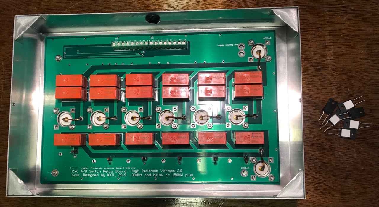
My KK1L board, showing the old resistors on the board, and the new ones on the desk.
While testing the KK1L Antenna Switch after mounting to the Single Point Ground (SPG), I noticed that some of the load resistors were no longer 50 ohms.
These resistors provide a load impedance whenever a antenna jack is not selected by either port A or Port B. This protects the antenna from static build-up as well as dissipating any coupled RF energy.
I originally used 50 ohm, 1/2 watt resistors I had on hand. Clearly they were not up to the task. On the ports for the shunt-fed tower, and the 80/40/20m trap dipole, these resistors were completely open. Both showed signs of overheating.
Most likely, these resistors succumbed to dissipating too much couple RF energy. I needed bigger ones. KK1L had 50 ohm, 50 watt resistors in his Mouser parts list, so that's what I ordered. These sorts of things come in handy, so I bought ten. Due to supply chain issues, they were back-ordered for months. But they finally arrived.
Replacing these parts is a pain. First, I had to remove the KK1L box from the SPG panel. Next, I had to remove the board from the aluminum box. Before I did that, I made sure to mark the locations the mounting screws for each resistor. To remove the board, I had to unsolder the eight connections to the SO-239 center conductors and bend them out of the way. Then came twenty-some nuts holding the board in place.
With the board separated from the box, I drilled the holes for the resistor mounting screws. I used a numbered drill bit the same size as the hole in the board to give me the largest tolerance. With the holes drilled and de-burred, my attention turned to the board.
Board with new resistors
Next step was to remove the existing resistors. Where they connect to the relays was easy, but the connections to the ground plane were harder. The ground plane tended to carry the heat away, making it hard to melt the solder without damaging the board. Getting these holes cleared of solder took a lot of effort.
Once done, the new resistors mount cleanly on the underside of the board. I oriented the resistors so the ceramic patch was toward the aluminum box. This patch does not appear electrically conductive.
After the resistors are soldered, the process is reversed to re-install the board in the aluminum box. In addition to the existing twenty-some nuts, there are also six new #4 screws and nuts to mount the resistors securely. With that in place, re-soldering the eight connections to the SO-239 center conductors completes the job.
I mounted the KK1L box to the SPG, and then re-tested all the switching combinations. This was to ensure I had connected the switching lines correctly.
I hope the new resistors are up to the job. I'll have to check on them in a few months to make sure.
As radio amateurs, taking proper precautions against lightning and electrical surges can be a difficult and expensive proposition. We often neglect them and rely on luck.
After reading Bonding and Grounding for the Radio Amateur, I decided it was worth the investment. I already had all ground connections - house, tower, station - bonded. What was missing was bonding the antenna connections to the ground as they entered the house. I needed a Single-Point Ground panel.
A Single-Point Ground is a metal panel or box providing a common bonding point for all cables as they enter a building. This metal is connected to the external ground rods, which are all bonded together. The idea is to bond the cables connected together, so that lightning or surge potentials all rise and fall together. Without a potential difference, damaging currents cannot flow.
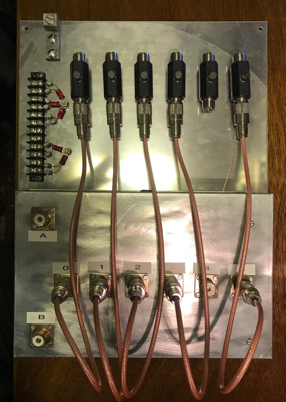
SPG panel ready to mount on basement wall
I cut a 0.090" Aluminum panel 12" by 16" and mounted the KK1L antenna switch to the bottom edge. I added lightning arrestors for the antenna coaxial cables, plus a barrier strip holding gas discharge tubes for the rotator and shunt antenna control cables.
I chose MFJ-272 lightning arrestors. I needed six of these, and the MFJ units were about $40 each. The Alpha Delta and Polyphaser units were more expensive. The arrestors are mounted to the panel with a single large screw, supplied with the arrestor.
Short coaxial jumpers connect the arresters to the KK1L switch. I made these out of 18 inches of RG-400 coax using new Amphenol UHF connectors and a UG-175 adapter. RG-400 is doubly-shielded, eliminating the potential for any coupling between the jumpers. (Notice I didn't quite have enough RG-400 for all six jumpers, so there are only five at the moment. I'll have to purchase more)
The panel mounts on the basement wall where the cables enter the house through a 4 inch PVC pipe. A grounding block connects a short piece of copper wire to an eight foot ground rod on the outside. The ground connection is also bonded to the perimeter ground wire between the house, tower and station grounds using a split bolt.
I had a bit of trouble with the coax running from the A and B ports of the KK1L to the operating desk. Since the coax to the antennas ended at the basement wall, I trimmed some coax from the antenna feed lines. To get the right length, I pulled the feed lines outside, then trimmed them from the far end. Simple, eh? Except the first one looped around and got stuck, and the cut piece ended up being about five feet too short.
The next feed line was a newer run of Davis Buryflex. I ran it to the A3S/A743, and then cut the right length. For some reason, I had problems with the connectors on both ends, but once they were redone, the cable worked as expected. For a short while, I thought the cable itself might be defective.
To do these tests, I made good use of my RigExpert AA-55 Zoom. Which of two pieces of old coax is any good? The cable loss test is quick and give one real numbers to compare. You just need to test the coax both open and shorted.
With the SPG installed, the next step is to automate the switching of the KK1L.
Cable management trays added to back of desktop selves.
Now that my station desktop is on wheels and has a set of nice shelves, I wondered might be done about the rats nest of wires hanging down from the back of the desk. Some kind of cable management system was needed.
These systems can be expensive. I found a solution on Amazon.com that worked pretty well. It is a kit of eight cable raceway trays about 15" long, 1.5" wide and just under 1" tall. All for just about $20.
These worked well with my desktop shelves. Three cable trays fit neatly on the back of the shelves just under the copper pipe ground bus bar. I mounted them using three short wood screws on each tray.
The tops of the trays either slide or snap off. The fingers on the sides are easily displaced to insert wires of just about any size. In some cases, cables are routed in the trays from one end of the shelves to the other.
From the picture, there are still a lot of wires, but it is neater and more manageable than before. Many of those are antenna coax or power connections. The antenna coax will be moving to the back wall of the basement once the Single-Point Ground (SPG) panel is in place.
I also improved the bonding between units. I'm using 1/2" tinned copper braid, a fork lug and a cable clamp around the 1/2" copper tube grounding bus. This creates a low-impedance connection between the equipment and the station ground. In a few cases, I had to drill a hole and add some #6 screws and nuts to make the connection.
The best part is, I still have five left-over cable management trays to use elsewhere.
Updated shelves as of January 2022. The AL-80A Amplifier is just off to the right side, on the desk.
Setting up my shack in my first home, in 1986, I needed to stack equipment. My operating position was a finished door on top of two filing cabinets, something that I used in my previous apartment. While the table was big enough, shelves were needed to easily access all my equipment.
I came up with a design using 1x12 lumber. There are three shelves, one 1", 12" and 22" above the tabletop. I chose these heights because it allowed me to slip my paper log books and other operating aids under the bottom shelf -- under the bottom row of gear.
I bought a stack of 1x12 boards, borrowed a friend's table saw and cut the pieces to length. I laid them on edge on the cement floor of my garage, glued the edges and pieced them together with wire brads. Everything lined up OK -- the result was pretty square.
35+ year old shelving unit, before it was removed from desk
The shelves were 48" wide ( 8 foot boards cut in half ), and had two uprights under each shelf. These shelves worked for several decades.
Over time, I noted problems. The upright supports limited the equipment I could put side by side, because only so much would fit. And the lowest shelf was problematic -- it meant my computer was in front of the shelf -- which meant my arms hung off the desk, with my forearms resting against the edge of the desk. This caused a lot of fatigue when contesting. Plus, I had stopped using paper logs back in 2006, so there was no reason for the lower shelf.
Micro-shack, before I moved.
I liked the layout I had back in the micro-shack. The desk surface was small (just a couple of inches wider than 5 feet), and the primary equipment sat on the desk itself, with other gear on a shelf. This meant I could re-position my gear at will. Best of all, the computer could be front and center, with my forearms resting comfortably on the desk itself.
After 35 years, the requirements came together. I needed a shelf unit with two shelves. The first shelf would be 12" above the desk, and the second shelf 22" above the desk. This left more than enough room to slide a 15-17" laptop under the bottom shelf. The shelves could be a little wider, to accommodate more equipment. Because my copper pipe grounding bar was a little more than 53" long, I opted to make the unit 52" wide.
I liked having the AL-80A amplifier on the right side of the desk, canted slightly to make the controls accessible, and allow for good cooling airflow. With a 52" wide self unit, this meant about 8" of unused desk space on the left-hand side. That was fine. That part of the desk is right next to a wall, and I don't put equipment that deep -- usually that's where my headphones and operating aides end up.
The bottom and top shelves would be separated by two uprights, with openings of roughly 17" on the left and right, and 15" in the middle. Under the bottom shelf, there would be no uprights. Instead, to keep the shelves from bowing, I used a piece of 1x4 as a sheer web at the back of the unit.
Here are the component dimensions used:
top (1x12) - 52”
shelf (1x12) - 50 1/2”
ends (1x12) - 21 3/4” (2)
separator (1x12) - 10” (2)
shear web (1x4) 50 1/2”
I bought the requisite 1x12 and 1x4 lumber, but didn't cut or assemble until later. This was unfortunate, because the lumber cupped a little bit as it dried out in my basement. This made the pieces a little harder to fit together. I used the same construction technique I used before -- glue and wire brads.
And even though I put the pieces together on my very flat workbench, a little bit of twist was introduced in the bottom shelf. It doesn't quite line up in the front like it should -- something I'll be looking at for the next 30+ years. I considered busting it apart and starting over, but I decided it would do as is.
Assembled unit with grounding bar installed
I intended to stain it and seal with polyurethane. However, I found that my stain had turned into a solid mass of jelly and was unusable. Instead, I applied three coats of polyurethane. The resulting finish is quite handsome.
The shelf unit is relatively light and quite sturdy. I'm sure it would support my weight, but I didn't try. The copper pipe grounding bar fastens to the 1x4. I use small hose clamps to attach wires to the grounding bar. This ensures that all gear is properly bonded to ground.
I'm very satisfied with the end result - plenty of room for gear on the desktop, with other gear on shelves at a handy height. The bits and pieces of equipment are slowly coming back to the operating desk, and I'm being careful in deciding what goes where -- it can get awfully cluttered.
I do love having a lot of space for computer gear on the desktop. I've had as many as three different laptops all running at the same time on the desk.
Now I've got to finalize where everything goes. I've already decided I need to move the P3, and the KK1L antenna switch matrix is going to end up on the basement wall on the Single-Point Ground panel.
When I first got into radio, in 1971, I barely knew what I was doing. I had done some shortwave DXing with my GR-81, but that rig worked much better on the AM broadcast band than anywhere else. Just before labor day of 1971, I put up my first outdoor antenna.
Previously, I had just used a spool of magnet wire strung around the ceiling of my attic bedroom. This was not a very good antenna. Just before school started in 1971, I bought a 25 foot roll of small speaker wire and unzipped it all. Soldering the two pieces together, this gave me 50 feet of antenna wire, which I strung out the window, across the garage and into a tree at the edge of the yard.
I was eager to try this new antenna, so I proceeded to tune across the AM broadcast band that evening, and log each station I could. I started about 9 PM, and kept tuning until midnight. The next evening, I continued the process.
Sep 3 log page.
That first night, I had started at the bottom of the band at worked my way upwards. The second evening, I continued upwards, but then reversed and went lower in frequency. This made more sense to me, and my later "countdowns" that I would make in subsequent years all started at the top of the broadcast band and continued toward the bottom.
Sep 4 log page.
This event inspired me that for the next several years, I would try to do a "countdown" around Labor Day weekend. It marked the end of the summer, but also the beginning of the radio season.
I remember it distinctly. I would sit patiently and wait for the AM stations to ID, generally at the top or bottom of the hour. If I got lucky, they would ID sooner.
Hard to believe that event was over fifty years ago.
I can't believe I haven't posted in over six months. It's been an interesting year. Things really heated up quite a bit at work in the late spring, and I finally got the opportunity to take a couple of nice vacation times in the summer before Covid sprung back up.
And then, in October, when I finally thought I was hitting my stride at work a year after a position change -- they laid me off....
So, I've been busy looking for new employment. I'm happy to say that I have accepted a position that starts in January, so perhaps I can catch up on some much needed writing before then.
Sometimes experiment pays off. You never know until you try.
I was reading an article about remotely controlling computers over the internet. It occurred to me that if I could do this, it would be easy to operate FT8 from my Gwinnett QTH when I was at the Fulton QTH. Although I have rigs in both locations, Gwinnett is where I have the K3, and can operate on 6m.
I started to research solutions. I found a product called RealVNC that can be licensed free for non-commercial use on up to five computers. Comes with a separate server and viewer product, and it works on Macs as well as Windows, Linux, even the Rasberry Pi.
You have to create an account on their web site, but the installation was easy. I have a MacBook Pro hooked to the K3 at the Gwinnett QTH. I installed the server there. Then I installed the viewer software on a couple of Macs, and one Windows computer.
Making the connection from Viewer to Server requires 2-factor authentication, so it is pretty secure.
This software worked great. I was easily able to connect to the MacBook Pro and use WSJT-X. The K3 has to remain turned on, and I have no way to remotely change antennas, so I left it switched to the 3-element 6m beam. I also have no way to rotate the antenna remotely (it uses Armstrong rotation...), so I left the beam pointing SouthEast. I was hoping to pick up some propagation to the Caribbean or perhaps Central or South America.
The first week of this experiment bore fruit the next day. I was in Fulton county, but checking I lucked into an opening to South America, where I worked two stations in Chile and two in Uruguay. Two new countries and four new grids! The next day, there was a powerful, but brief opening to the Cayman Islands, and Belize.
While one cannot predict 6m propagation, remote operating gives me a tool so I don't miss out on openings while I'm away from the Gwinnett QTH.
This is only Level 0 of Remote Operating. I can only do FT8, and I can't change bands. That's next, I'm working on an automatic antenna switch driver to choose an antenna by the band selection of the K3.