Simple ESR meter
25 June 2023 at 21:24
Almost a copy from here.

Diagram from the original site:
Inside:

and during testing:

Works nice, handy for testing old caps.
Have a nice day!
![]()

Almost a copy from here.
Diagram from the original site:
Inside:
Works nice, handy for testing old caps.
Have a nice day!
![]()
As title says; a simple capacitance meter.
One youtube video by VK3YE was enough to get me started building, after all, the meter that I was using before was not behaving correctly (latter found the problem).
The outcome was this:

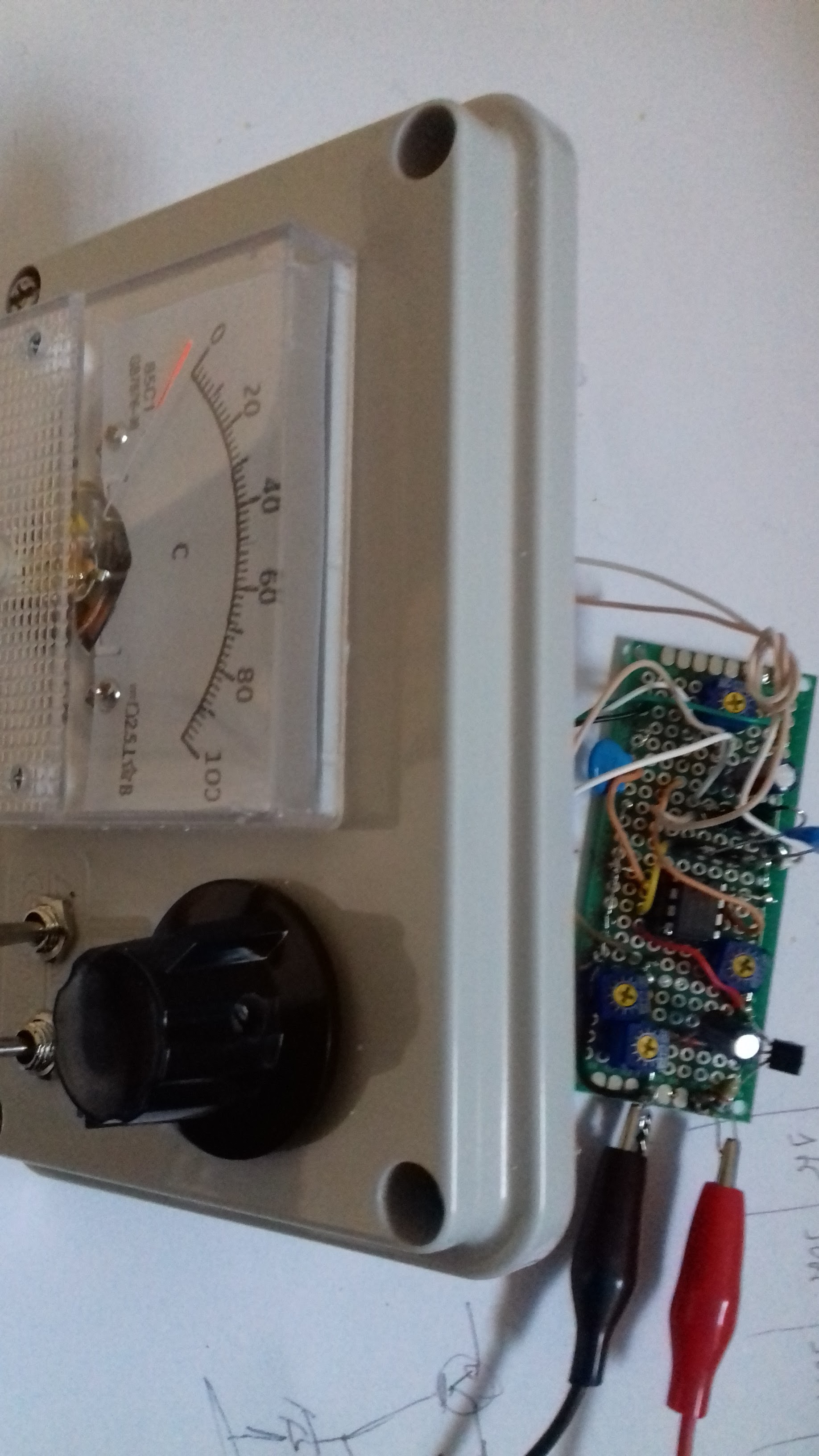


To calibrate I used a 68pF and 27pF capacitor, the idea was not to have highest precision possible only to be in a position of having certain about unmarked capacitors.
Some description/schematic from here and here:

I used different Ge diodes and the 10K pot was changed for 2 of 5K in series to give better adjustment range. The Zener was changed to 6.8v.
Ranges like this:
E: 100pF
D: 1nF
C: 10nF
B: 100nF
A: 1uF
Have a nice day!
![]()
Not planing to build any electronic clock but who knows. Just found one of those round clock crystals and decided to give it a go.
The diagram and assembly


Have a nice day!
![]()
Part of a project on 1.2Ghz that will include this band-pass filter.
Main dimensions got online via the tool here: https://www.changpuak.ch/electronics/interdigital_bandpass_filter_designer.php
Some details of similar construction for different frequency range (ADS-B) here: https://keptenkurk.wordpress.com/2014/11/05/a-homebrew-1090mhz-ads-b-filter/
My construction:


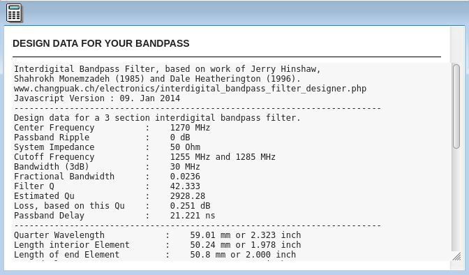

And the outcome:

Regarding results; not the best optimization for attenuation but not bad either considering the dimensions and construction not to the greatest dimensional andards:

Have a nice day!
![]()
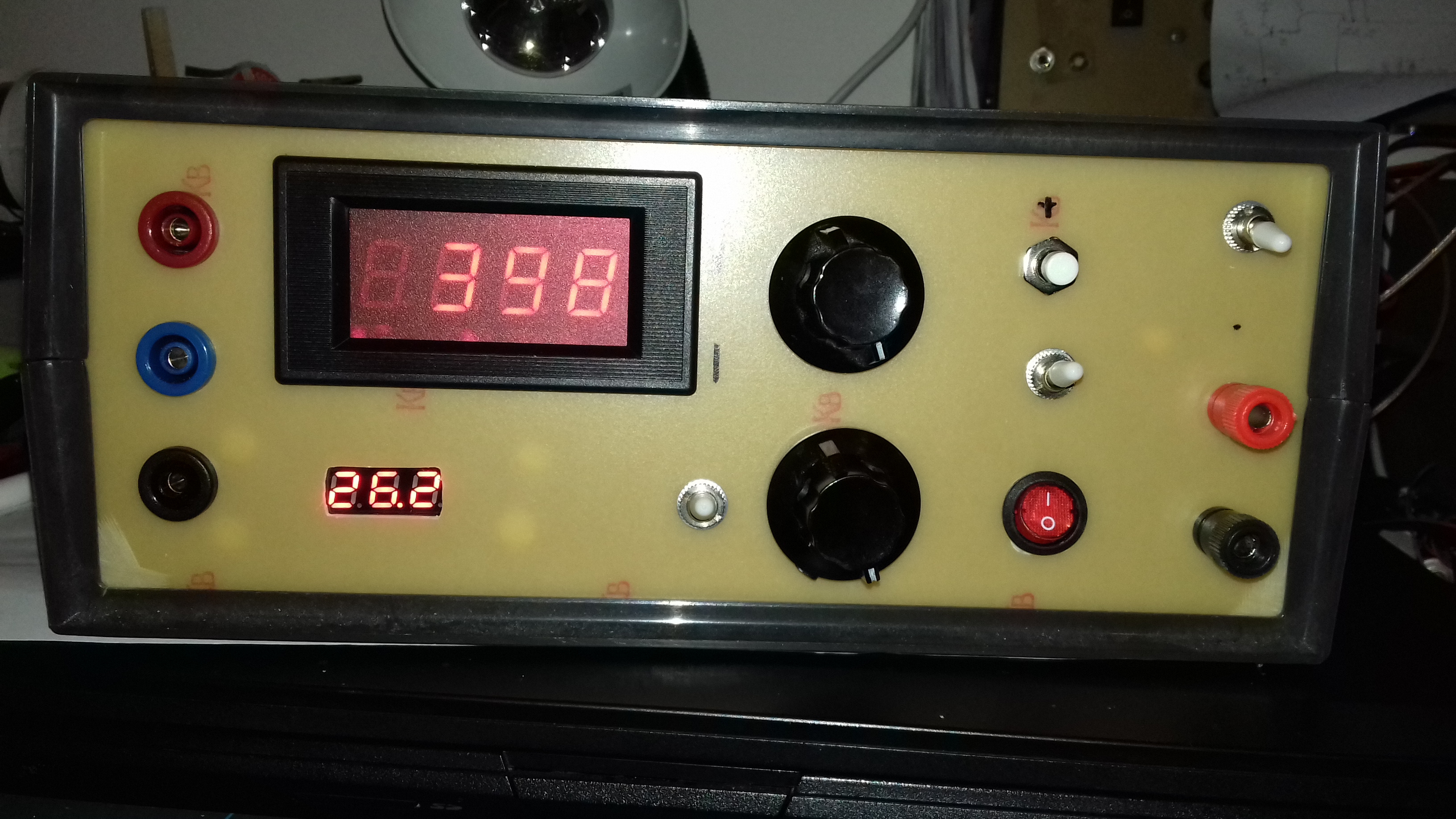
A power supply for a future tube/valve tester

Main circuit for the positive side is similar to the one bellow (the top section),

The negative supply is similar to the diagram bellow("Standard") with small adaptations to allow 2 different ranges:

There's a separate transformer for each of the supplies; the filament the positive and the negative, also other separate on to power the voltage meters.
Was added a small relay controlled high voltage supply output so I don't get accidentally zapped, you need to constantly press enable button to have high voltage output at the terminals.
The internals:


Working during testing:
Now I still need the tube socket and metering part for the full valve/tube test set, eventually something like this (only the top section):

Have a nice day!
![]()
I have some spare ATmega328 chips that are not programed and can be used in some projects specially now the prices Arduino boards got some inflation.
In order to upload the program to the IC's you will need to burn first the bootloader, at least so that later you then upload via de Arduino IDE.
Schematic and instruction are from here: https://docs.arduino.cc/built-in-examples/arduino-isp/ArduinoISP
End result:

Another view:

For uploading: select the Arduino programmer USB port and then the programmer type "Arduino as ISP", in the end just "burn bootloader".

After bootloader burn:

Have a great day!
![]()
As part of the construction of a QO-100 station decided to try and convert a common satellite LNB from internal PLL crystal reference to an external one.

This is the inside of the LNB after plastic and metal cover removed:

Another view bellow. The crystal oscillator is on the other side of the PCB so it's needed to de-solder the F plugs terminals (top left and right):

After completion of the operation I can confirm It does work, still need to do more testing with different input signal reference, at the moment it accepts/works from around -10dbm to 0 dbm. Also tried to inject different reference besides the 25Mhz to shift the IF and works with ref. higher than the 25Mhz, bellow testing with 25.787Mhz as the PLL reference
The mod bellow, I also had to remove one cap from the input line to the output filter so that there is no load to the reference signal in.

This is the original schematic (it's a RDA3567 chip on the LNB board) with the mods made:

The capacitor used was one of the ones that were connected to the 25Mhz crystal on the original diagram
To remove the original crystal since I don't have SMD tools, I placed the iron with a bit of solder on top of it and waited for warming up the underlying terminals until it could be removed (note: this voids the warranty).
Another view of the LNB inside:

I also tried injecting on the LNB a parallel signal from the reference oscillator in the ADF4351 generator board to good success. Bellow the part where I took the signal from the ADF4351 reference:

I connected to the terminal normally used for the reference input and bridged the missing place for the 0 ohm resistor case you reference it externally.
Let's see in the future how stable is this internal reference of the AD4351, if good enough it avoids having to build an external TCXO for the LNB.
Have a nice day!
![]()
Another one for the list of projects with the ADF4351, following the ADF4351 Signal Generator and the ADF4351 signal generator with sweep.
This one to be used on a future project, a transverter for QO-100 satellite where a TX and RX frequency will be needed, depending if RX or TX enabled. The original design of the RX for around 50Mhz is that it can be divided by two so that signal will drive the 25Mhz oscillator of the LNB. I'll probably do that way for the LNB but also as full down conversion from 790Mhz.
Main code is from F1CJN at: https://github.com/F1CJN/ARDUINO-ADF4351-QO-100/blob/master/ADF4351_Dual_251119.ino with small changes for my particular board and needs.
The end result:
The code (will change the TX and RX frequency for my needs in the future):
Original at: https://github.com/F1CJN/ARDUINO-ADF4351-QO-100/blob/master/ADF4351_Dual_251119.ino
Bellow with changes:
///// code adf4351_dual_v1.ino
/// look for " PFDRFout=25; // Frequence de reference" if using a 10Mhz reference /// on the board
// ADF4351 with fixed frequency
// By Alain Fort F1CJN november 29,2019
// alain.fort.f1cjn@orange.fr
//
//
//
// ****************************************************** FRANCAIS *******************************************************
// Ce programme permet de programmer un ADF 4351 avec deux fréquences fixes et en utilisant une fréquence de reférence de 10 MHz.
// La premiére frequence frequence est utilisée avec un convertisseur émission (RX=0 et la seconde avec RX=1.Selection par PIN 5
// Les fréquence de sortie peuvent être modifiées aux lignes 79 et 80 en conservant le format.
// La frequence de reference peut être modidiée à la ligne ligne 70 (10MHz par défaut)
// ********************************************* HARDWARE IMPORTANT *******************************************************
// Avec un Arduino UN0 : utilise un pont de résistances pour réduire la tension, MOSI (pin 11) vers
// ADF DATA, SCK (pin13) vers CLK ADF, Select (PIN 3) vers LE
// Resistances de 560 Ohm avec 1000 Ohm à la masse sur les pins 11, 13 et 3 de l'Arduino UNO pour
// que les signaux envoyés DATA, CLK et LE vers l'ADF4351 ne depassent pas 3,3 Volt.
// Pin 2 de l'Arduino (pour la detection de lock) connectee directement à la sortie MUXOUT de la carte ADF4351
// La carte ADF est alimentée en 5V par la carte Arduino (les pins +5V et GND sont proches de la LED Arduino).
// ***********************************************************************************************************************
//
//
// *************************************************** ENGLISH ***********************************************************
// This software is used to programm an ADF4351 with Two fixed frequency, using a 10 MHz reference frequency.
// The frequency can be changed at lines 79 and 80, using the same format.Frequency selection is done with Arduino PIN 5.
// The reference frequency can be changed at line 70, using the same format (Default 10 MHz)
// ******************************************** HARDWARE IMPORTANT********************************************************
// With an Arduino UN0 : uses a resistive divider to reduce the voltage, MOSI (pin 11) to
// ADF DATA, SCK (pin13) to ADF CLK, Select (PIN 3) to ADF LE
// Resistive divider 560 Ohm with 1000 Ohm to ground on Arduino pins 11, 13 et 3 to adapt from 5V
// to 3.3V the digital signals DATA, CLK and LE send by the Arduino.
// Arduino pin 2 (for lock detection) directly connected to ADF4351 card MUXOUT.
// The ADF card is 5V powered by the ARDUINO (PINs +5V and GND are closed to the Arduino LED).
#include <SPI.h>
#define ADF4351_LE 3
uint32_t registers[6] = {0x4580A8, 0x80080C9, 0x4E42, 0x4B3, 0xBC803C, 0x580005} ; // 437 MHz avec ref à 25 MHz
//uint32_t registers[6] = {0x3D88FA8, 0x8009F41, 0x14E42, 0x4B3, 0x91003C, 0x580005} ; // 1969,501 MHz avec ref à 10 MHz
//uint32_t registers[6] = {0, 0, 0, 0, 0xBC803C, 0x580005} ; // 437 MHz avec ref à 25 MHz
int address,modif=0;
unsigned int i = 0;
double FreqTX, FreqRX, RFout, REFin, INT, PFDRFout, OutputChannelSpacing, FRACF;
double RFoutMin = 35, RFoutMax = 4400, REFinMax = 250, PDFMax = 32;
unsigned int long RFint,RFintold,INTA,RFcalc,PDRFout, MOD, FRAC;
byte OutputDivider;byte lock=2; byte RX=1;
unsigned int long reg0, reg1;
void WriteRegister32(const uint32_t value) //Programme un registre 32bits
{
digitalWrite(ADF4351_LE, LOW);
for (int i = 3; i >= 0; i--) // boucle sur 4 x 8bits
SPI.transfer((value >> 8 * i) & 0xFF); // décalage, masquage de l'octet et envoi via SPI
digitalWrite(ADF4351_LE, HIGH);
digitalWrite(ADF4351_LE, LOW);
}
void SetADF4351() // Programme tous les registres de l'ADF4351
{ for (int i = 5; i >= 0; i--) // programmation ADF4351 en commencant par R5
WriteRegister32(registers[i]);
}
//************************************ Setup ****************************************
void setup() {
Serial.begin (9600); // Serial to the PC via Arduino "Serial Monitor" at 9600
pinMode(2, INPUT); // PIN 2 en entree pour lock
pinMode(5, INPUT); // Pin 5 for TX/RX
pinMode(ADF4351_LE, OUTPUT); // Setup pins
digitalWrite(ADF4351_LE, HIGH);
SPI.begin(); // Init SPI bus
SPI.setDataMode(SPI_MODE0); // CPHA = 0 et Clock positive
SPI.setBitOrder(MSBFIRST); // poids forts en tête
PFDRFout=25; // Frequence de reference
RFintold=1234;//pour que RFintold soit different de RFout lors de l'init
RFout = RFint/100 ; // fréquence de sortie
OutputChannelSpacing = 0.005; // Pas de fréquence min
//******************************************************
FreqTX=1969.501;
FreqRX=51.8462;
//******************************************************
RX=1; //
// ct2gqv
pinMode(6, OUTPUT); // PIN 6 for display if on tx and blink 3 times during boot.
digitalWrite(6, HIGH); delay(500); digitalWrite(6, LOW); delay(500);
digitalWrite(6, HIGH); delay(500); digitalWrite(6, LOW); delay(500);
digitalWrite(6, HIGH); delay(500); digitalWrite(6, LOW);
} // Fin setup
void loop()
{
//**********************************************
RX = digitalRead(5); // reading RX/TX
if (RX==0){RFout=FreqTX; digitalWrite(6, HIGH);} // output frequency selection // ct2gqv put out 6 high to display we are in tx
if (RX==1){RFout=FreqRX; digitalWrite(6, LOW);} // output frequency selection // ct2gqv put out 6 high to low since we are in rx
RFint=RFout;
//********************************************
if (RFint != RFintold) {
if (RFout >= 2200) {
OutputDivider = 1;
bitWrite (registers[4], 22, 0);
bitWrite (registers[4], 21, 0);
bitWrite (registers[4], 20, 0);
}
if (RFout < 2200) {
OutputDivider = 2;
bitWrite (registers[4], 22, 0);
bitWrite (registers[4], 21, 0);
bitWrite (registers[4], 20, 1);
}
if (RFout < 1100) {
OutputDivider = 4;
bitWrite (registers[4], 22, 0);
bitWrite (registers[4], 21, 1);
bitWrite (registers[4], 20, 0);
}
if (RFout < 550) {
OutputDivider = 8;
bitWrite (registers[4], 22, 0);
bitWrite (registers[4], 21, 1);
bitWrite (registers[4], 20, 1);
}
if (RFout < 275) {
OutputDivider = 16;
bitWrite (registers[4], 22, 1);
bitWrite (registers[4], 21, 0);
bitWrite (registers[4], 20, 0);
}
if (RFout < 137.5) {
OutputDivider = 32;
bitWrite (registers[4], 22, 1);
bitWrite (registers[4], 21, 0);
bitWrite (registers[4], 20, 1);
}
if (RFout < 68.75) {
OutputDivider = 64;
bitWrite (registers[4], 22, 1);
bitWrite (registers[4], 21, 1);
bitWrite (registers[4], 20, 0);
}
INTA = (RFout * OutputDivider) / PFDRFout;
MOD = (PFDRFout / OutputChannelSpacing);
FRACF = (((RFout * OutputDivider) / PFDRFout) - INTA) * MOD;
FRAC = round(FRACF); // On arrondit le résultat
registers[0] = 0;
registers[0] = INTA << 15; // OK
FRAC = FRAC << 3;
registers[0] = registers[0] + FRAC;
registers[1] = 0;
registers[1] = MOD << 3;
registers[1] = registers[1] + 1 ; // ajout de l'adresse "001"
bitSet (registers[1], 27); // Prescaler sur 8/9
bitSet (registers[2], 28); // Digital lock == "110" sur b28 b27 b26
bitSet (registers[2], 27); // digital lock
bitClear (registers[2], 26); // digital lock
SetADF4351(); // Programme tous les registres de l'ADF4351
RFintold=RFint;//modif=0;
}
} // fin loop
//// end code
Have a nice day!
![]()
No big troubleshooting here, the HP3312A function generator had been developing small fault over time, the last time I used it was not outputting signal or with the wrong shape, so decided to see what could be done.
This was the "sinusoidal" output:
Not good! Also the frequency was not in line with the bezel markings.
Here's the offending component on top board near the front panel.
The reference marked in the capacitor, if needed:
TRW 8508
HEW-331
.5MF +/- 10%
50 VDC
Better now after replacement, I didn't had 0.5MF as originally so by mistake placed a 2.2uF, got better but still some distortion seen:
I then replaced by a 1uF one and now it's perfect, in the future I will probably try to find the right value (0.5uF) and replace.
Have a nice day!
![]()
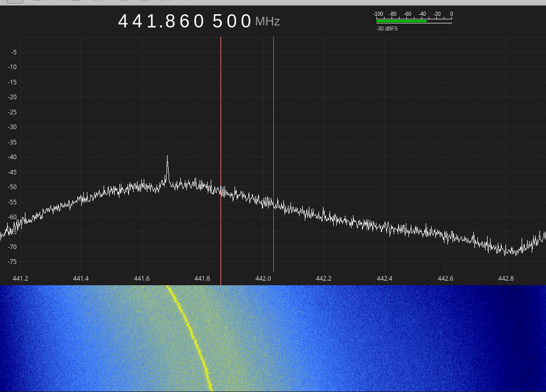
Had this little device for some time, an offer from a fellow ham some time ago (thank you Allan).
Schematic used is similar to the datasheet at: https://www.minicircuits.com/pdfs/PGA-103+.pdf
On the sweep on the spectrum analyzer this is what you get.
Other sources of information with more comprehensive details here:
http://www.g4ddk.com/PGA103amp.pdf
(includes an HPF design for 130Mhz)
https://vu2bfo.in/pga-103-lna/
https://www.w6pql.com/LNAs%20(preamps)%20and%20MMICs.htm
Have a great day!
![]()
Had this build for some time, now it's time to show.
I was doing some experiments on the 10Ghz band and wanted a way of looking at the signals. Because the spectrum analyser I have only good to 1.5Ghz had to find a cheap way of doing it to get this:
The diagram explanation: a dbm mixer (Watkins-Johnson M80LCA) with a local oscillator based on a FVC99 10Ghz oscillator module (cheapest VCO I could find for 10Ghz). Some preamps on the input and output using 2Ghz preamp modules and replacing the MMIC amplifiers for the ones like Corvo NLB300 or ERA-1 that are good to 10Ghz.
![]()
The basic design:
There is no stability control on the FVC99 oscillator, still working on a PLL system (maybe one of these days) but in my case I have two select positions, one: VCO is controlled by a single pot (like on the diagram) and the other position controlled by an EIP371 frequency counter (from the Lo Out via directional coupler) that makes the PLL loop. With EIP371 and since the output voltage of the loop is very small the control range seats near 9.5Ghz, there is an option of extending the range like on the EIP manual:
Or with a similar diagram, a multiply by 10 of the PLL voltage out of the EIP371, that would be enough to use the full range of the FVC99.
For now I use 9.5 Ghz if using the EIP371 for more stability and around 10Ghz set by the pot ("Flo" on the panel) if it's just a quick test.
Here the EIP working as external PLL controling the FVC99 so the LO gets more stable.
On the Rigol DSA815 spectrum analyser you can set the input offset to get the display right on the band of interest
Displaying here a 10Ghz signal using the 9.5Ghz Lo frequency
Inside view:
Some other images during prototype development:
Testing during early days of the prototype with a 10Ghz homemade flange to SMA adapter and a pipe cap filter:
Anyhow, not a measuring device but it serves the purpose of checking if you have any signal around the 10Ghz band and for experiments, still very happy with the outcome and sensitivity.
Have a nice day!
![]()
Had to program a 16F628 PIC for a frequency counter kit that let the magic smoke out.
First I tested with the PIC included on a different kit to see if would work, in fact looks like all these kits use the same code from DL4YHF.
The programmer diagram was a re-use of one that I used in the past, see schematic:

From here and other ideas here.
I had some problems making it to run on the laptop but using the serial port from the desktop it worked.
Commands to use were this ones:
# picprog --device=pic16f628 --pic /dev/ttyS0 --erase
# picprog --input-hexfile=counter2.hex --device=pic16f628 --pic /dev/ttyS0 --burn
(Picprog version 1.9.1)
I did not had a serial port plug so resorted to use some terminals, for a one of, it's ok

The assembly re-using the board from another test project:

The programmer that had the PIC issue, now running:


...eventually one day ill get a "proper" programmer but for one PIC every so often it's perfectly fine this way.
That's it, have a nice day!
![]()
I have an unused TV aerial rotator and would be good to put it, along with an motorized elevation control, for some satellite work.
Googling around for some Arduino controller code I found from fellow ham YO3RAK at: https://racov.ro/index.php/2020/12/09/arduino-based-antenna-rotator-part3-software-tracking-update/
and:
https://create.arduino.cc/projecthub/viorelracoviteanu/antenna-rotator-controller-compatible-with-tracking-software-48f9cd#code
a nice bit of a project.
Compiled it along with some LCD library changes and noted that was not fully working with rotctld (Hamlib 1.2.15.3) and gredict (1.3) on Linux. Long story short I ended up starting my own code, half way trough discovered what looks like a different implementation or EasyComm II protocol on hamlib in Linux depending on version.
At some point trough my code I reverted to do changes on YO3RAK code to accommodate my setup, a mix of hamlib 1.2.15.3 and 3.1 along with gpredict 1.3 and 2.0-4. Now works fine on both implementations in Linux.
Since I've seen some posts with similar issues here's what I got while testing regarding behaviour:
hamlib 1.2.15:
Query position: "!"
Return: "TM0 AZ<AZIM>0.0 EL<ELEVATION>0.0"
See "0.0" appended, that sends 10x more angle, else gpredict will receive angle/10
hamlib 3.1:
Query position: "AZ EL ."
Return: "AZ<AZIM>.0 EL<ELEVATION>.0"
Here only appending the decimal point and works correctly on gpredict 2.0-4.
To start the process, besides having the the Arduino rotator controller you need to start rotctld similar to:
rotctld -m 202 -r /dev/ttyUSB0 -s 9600 -T 192.168.0.14 -t 4533
where 192.168.0.14 will be your computer IP address, rotctld will listen on port 4533 for rotator commands from gpredict. /dev/ttyUSB0 will be the virtual USB port of the Arduino/rotator controller device. So, in simple terms, rotctld connects to the Arduino and listens on IP commands that gpredict sends to control the rotator.
Some images of gpredict and rotctld in action along wiht the Arduino code:


To configure gpredict will be similar to this:

To connect to the rotator, this way:

I still don't have the hardware, will update when done.
The code bellow, since blogspot breaks a bit on the formating send me and email if you need a file with the code, file is: original_ant_rotator_easycom2_aug2021_mod_ct2gqv_v3.ino
/// code start
/* AZ/EL Antenna Rotator controller for Arduino - DC motors
* ========================================================
* Uses EasyComm protocol for computer - Tracking Software
* Manual command by means of two rotary encoders AZ - EL
*
* Viorel Racoviteannu
* https://www.youtube.com/channel/UCiRLZX0bV9rS04BGAyUf-fA
* https://racov.ro
* YO3RAK@gmail.com
*
* I cannot take any responsibility for missuse of this code
* or any kind of damage it may occur from using this code.
*
* dec 2020 v2 - improved serial comm stability
* january 2021 - improved near target dead-zone, for which antenna won't move
* apr 2021 - improved serial comm stability
* jun 2021 - error proportional power for tracking movement
* aug 2021 - faster USB update, cold switching Az/El direction, small optimizations in the code
*
* Mods by CT2GQV bellow
* 2021-10-31 added code to accept AZ EL as query since Hamlib 3.1 sends it, while Hamlib 1.2.15.3 sends the "!"
* 2021-10-30 Original code moded to acept the "!" from Hamlib 1.2.15.3 using gpredict in 1.3 Linux
* to include parsing of rotctld commands from Linux via gpredict.
* gpredict will connect to "rotator" (rotctld) with IP 192.168.0.14 (example)
* and rotctld will listen to IP 192.168.0.14 and send commands for the arduino rotator
* controler (from YO3RAK with mod CT2GQV) * via serial USB
* ex: rotctld -m 202 -r /dev/ttyUSB0 -s 9600 -T 192.168.0.14 -t 4533.
* ex: rotctld -m 202 -r /dev/<arduino usb> -s 9600 -T <your IP address to listen> -t <port to listen>
*
*
*/
#include <Wire.h> // Library for I2C communication
#include <LiquidCrystal_I2C.h> // Library for LCD
// Wiring: SDA pin is connected to A4 and SCL pin to A5.
// Connect to LCD via I2C, default address 0x27 (A0-A2 not jumpered)
// LiquidCrystal_I2C lcd(0x27, 16, 2); // address, chars, rows.
// CT2GQV mod
LiquidCrystal_I2C lcd(0x27,2,1,0,4,5,6,7); // 0x27 is the default I2C bus address (this could be different for some modules)
// how much serial data we expect from rotctld before a newline
const unsigned int MAX_INPUT = 14; // "AZ360.0 EL90.0", that is: 14 char's
int soft_az,soft_el ; // to hold the azimuth and elevation values sent from the gpredict via rotctld software
// end mod CT2GQV
// declaring custom symbol for up/down arrow
byte DownArrow[8] = {
B00000,
B00100,
B00100,
B00100,
B10101,
B01110,
B00100,
B00000
};
byte UpArrow[8] = {
B00000,
B00100,
B01110,
B10101,
B00100,
B00100,
B00100,
B00000
};
/***********************************THIS IS WHERE YOU REALY TWEAK THE ANTENNA MOVEMENT***************/
// ANTENNA potentiometers CALIBRATION
int AzMin = 1; //begining of the potentiometer
int AzMax = 1023; //end of the potentiometer
int ElMin = 1;
int ElMax = 1023;
// Allowed error for which antennna won't move. Minimum 1 degree
int AzErr = 9;
int ElErr = 4;
// Angle difference where soft stop begins
int Amax = 25; //azimuth
int Emax = 15; //elevation
// min and max power for motors, percents;
int PwAzMin = 40; //minimum power for which the motor doesn't stall and starts under load
int PwAzMax = 100; //full power for the fastest speed
int PwElMin = 30;
int PwElMax = 100;
int PwAz = 0; //calculated power to be transmitted to motor (percents);
int PwEl = 0;
/***************************************************************************************************/
// Azim encoder variables
enum AzPinAssignments {
AzEncoderPinA = 2, // encoder right
AzEncoderPinB = 3, // encoder left
AzClearButton = 4}; // encoder push
unsigned int lastReportedPos = 1; // change management
static boolean rotating = false; // debounce management
// interrupt service routine vars
boolean A_set = false;
boolean B_set = false;
//Elev encoder variables
enum ElPinAssignments{
ElEncoderPinA = 6, // encoder right
ElEncoderPinB = 5, // encoder left
ElClearButton = 7}; // encoder push
int aState;
int aLastState;
// other variables
int AzPotPin = A0; // select the input pin for the azim. potentiometer
int AzRotPin = 12; // select the out pin for rotation direction
int AzPWMPin = 11; // select the out pin for azimuth PWM command
int TruAzim = 0; // calculated real azimuth value
int ComAzim = 0; // commanded azimuth value
int OldTruAzim = 0; // to store previous azimuth value
int OldComAzim = 0;
char AzDir; // symbol for azim rot display
int AzEncBut = 1; // variable to toggle with encoder push button
int ElPotPin = A1; // select the input pin for the elev. potentiometer
int ElRotPin = 13; // select the out pin for elevation rotation direction
int ElPWMPin = 10; // select the out pin for elevation rotation PWM command
int TruElev = 0; // calculated real elevation value
int ComElev = 0; // commanded elevation value
int OldTruElev = 0; // to store previous elevation value
int OldComElev = 0;
char ElDir; // symbol for elev. rot display
// flags for AZ, EL tolerances
bool AzStop = false;
bool ElStop = false;
int ElUp = 0; // 1 = Elevation Dn, 0 = Elevation STOP, 2 = Elevation Up
//averaging loop
const int numReadings = 25;
int readIndex = 0; // the index of the current reading
int azimuth[numReadings]; // the readings from the analog input
int elevation[numReadings];
int totalAz = 0; // the running total
int totalEl = 0;
// variables for serial comm
String Azimuth = "";
String Elevation = "";
String ComputerRead;
String ComputerWrite;
bool AZser = false;
bool ELser = false;
bool ANTser = false;
/*************** END VARIABLE DECLARATION ************/
void setup() {
Serial.begin(9600);
Serial.setTimeout(50); // miliseconds to wait for USB sata. Default 1000
// Initiate the LCD:
// lcd.begin(16,2);
// lcd.init();
// lcd.backlight();
// LCD initialization
lcd.begin(16, 2); // LCD set for 16 by 2 display
lcd.setBacklightPin(3,POSITIVE); // (BL, BL_POL)
lcd.setBacklight(HIGH); // LCD backlight turned ON
lcd.clear();
//creating custom symbol for up/dwn arrow
lcd.createChar(1, DownArrow);
lcd.createChar(2, UpArrow);
// pin declaration
pinMode(AzRotPin, OUTPUT); //declaring azim. rotation direction Pin as OUTPUT
pinMode(AzPWMPin, OUTPUT); //declaring azimuth PWM command Pin as OUTPUT
pinMode(ElRotPin, OUTPUT); //declaring elev. rotation direction Pin as OUTPUT
pinMode(ElPWMPin, OUTPUT);
pinMode(AzPotPin, INPUT);
pinMode(ElPotPin, INPUT);
pinMode(AzEncoderPinA, INPUT);
pinMode(AzEncoderPinB, INPUT);
pinMode(AzClearButton, INPUT);
pinMode(ElEncoderPinA, INPUT);
pinMode(ElEncoderPinB, INPUT);
pinMode(ElClearButton, INPUT);
// AzEncoder pin on interrupt 0 (pin A)
attachInterrupt(0, doEncoderA, CHANGE);
// AzEncoder pin on interrupt 1 (pin B)
attachInterrupt(1, doEncoderB, CHANGE);
// Reads the initial state of the ElEncoderPinA
aLastState = digitalRead(ElEncoderPinA);
// write on display name and version
lcd.setCursor(0, 0); // Set the cursor on the first column first row.(counting starts at 0!)
lcd.print("EasyCom AntRotor"); // display "..."
lcd.setCursor(0, 1); // Set the cursor on the first column the second row
// changed to reflect mod by CT2GQV
lcd.print("*YO3RAK/CT2GQV*");
delay(2000); // keep for 2 seconds
// display Azim. and Elev. values
lcd.setCursor(0, 0);
lcd.print("Azm.---" + String(char(223)) + "=Cd.---" + String(char(223))); // char(223) is degree symbol
lcd.setCursor(0, 1);
lcd.print("Elv. --" + String(char(223)) + "=Cd. --" + String(char(223)));
/* initialization of the averaging loop */
// this is to set azim-command the same value as real, not to jerk the antenna at start-up
TruAzim = (map(analogRead(AzPotPin), AzMin, AzMax, 0, 359)); // azimuth value 0-359
if (TruAzim<0) {TruAzim=0;}
if (TruAzim>359) {TruAzim=359;} // keep values between limits
TruElev = (map(analogRead(ElPotPin), ElMin, ElMax, 0, 90)); // elev value 0-90
if (TruElev<0) {TruElev=0;}
if (TruElev>90) {TruElev=90;} // keep values between limits
// initialize all the readings
for (int thisReading = 0; thisReading < numReadings; thisReading++) {
azimuth[thisReading] = 0;
elevation[thisReading] = 0;
}
ComAzim = TruAzim;
ComElev = TruElev;
OldTruAzim = TruAzim;
OldComAzim = ComAzim;
OldTruElev = TruElev;
OldComElev = TruElev;
DisplAzim(TruAzim, 4,0);
DisplAzim(ComAzim,12,0);
DisplElev(TruElev, 5,1);
DisplElev(ComElev,13,1);
}
// end SETUP
// here to process incoming serial data after a terminator received
void process_data (const char * data) // ct2gqv
{
char data1[3]="", data2[3]=""; // to hold azimuth and elevation sent by gpredict/rotctld
int j = 0, k = 0 ; // for counters to insert in data1 and data2
int select = 1; // holding which data to insert the character
// for AZxxx ELxxx command but will also try to parse something like "AZ EL." so we don't do it if data[3] == 'E'
if (data[0] == 'A' && data[1] == 'Z' && data[3] != 'E'){ // we wait for the AZ command, it comes similar to AZ3599.0 EL900.0
for (int i = 0; i < MAX_INPUT; i++)
{
char x = data[i];
if (x == ' ') {select = 2;}; // we are done, we had the first space and means we are on to the second value for azimuth
if (x == '.') {select = 3;}; // we have a dot so we don't parse the data1 until we have the previous wich is a spce then we do data2
if (isdigit(x) == 0)
{
// do nothing only if needed to get AZ or EL string's
}
else // it's a number
{
if (select == 1) { // holds the azimuth characters until the dot
data1[k] = x;
k++; };
if (select == 2) { // holds the elevation
data2[j] = x;
j++; };
}
}; // end of if loop to separate AZ and EL from the rotator command software
soft_az = atoi(data1);
soft_el = atoi(data2);
// we need to send now the data to the original code
ComAzim = soft_az;
ComElev = soft_el;
};
// for "AZ EL ." command of query position on gpredict 2.0-4 since it's diferent from gpredict 1.3 (we only care about knowing if "AZ EL" was received)
if (data[0] == 'A' && data[1] == 'Z' && data[3] == 'E' && data[4] == 'L'){
// removed the "TM0" (ComputerWrite = "TM0 AZ...") on the ComputerWrite string for gpredict 2.0-4 , also on gpredict 2.0-4 the x10 of the el/az looks fixed so removed
// the adding of "0.0" to the sent position and elevation, now only decimal dedgrees is send ".0"
ComputerWrite = "AZ"+String(TruAzim)+".0 EL"+String(TruElev)+".0"; // need to be x10 (add 0.0) or gpredict 1.3 will read divide by 10 (might be rotctld causing it also).
Serial.println(ComputerWrite);
};
// for "SA SE ." command of stop azimuth and stop postion.... blank for now.. need to study betther the code
if (data[0] == 'S' && data[1] == 'A' && data[3] == 'S' && data[4] == 'E'){
// how should we stop here ? and should we report something ? Should we apply breaks on rotator ?
// for now we do nothing.....to be continued...
};
} // end void process_data
void processIncomingByte (const byte inByte) // CT2GQV
{
static char input_line [MAX_INPUT];
static unsigned int input_pos = 0;
switch (inByte)
{
// for gpredict 1.3 w report the position here, there is also a factor of 10 that needs to be send, so it's "0.0" apended
// this is on Hamlib 1.2.15.3 but diferent on Hamlib 3.1 where it sends "AZ EL"
case '!': // rotctld when sending "!" is asking rotator position so let's send it
ComputerWrite = "TM0 AZ"+String(TruAzim)+"0.0 EL"+String(TruElev)+"0.0"; // need to be x10 (add 0.0) or gpredict 1.3 will read divide by 10 (might be rotctld causing it also).
Serial.println(ComputerWrite);
break;
case '\n': // end of text
input_line [input_pos] = 0; // terminating null byte
// terminator reached! process input_line here ...
process_data (input_line);
// reset buffer for next time
input_pos = 0;
break;
case '\r': // discard carriage return
break;
default:
// keep adding if not full ... allow for terminating null byte
if (input_pos < (MAX_INPUT - 1))
input_line [input_pos++] = inByte;
break;
} // end of switch
} // end of processIncomingByte
void loop() {
/************** FYI, this loop repeats 500 times per second !!! **************/
// AZIMUTH/ELEVATION AVERAGING LOOP
// subtract the oldest value
totalAz = totalAz - azimuth[readIndex];
totalEl = totalEl - elevation[readIndex];
// read from the sensor:
azimuth[readIndex] = (map(analogRead(AzPotPin), AzMin, AzMax, 0, 359));
elevation[readIndex] = (map(analogRead(ElPotPin), ElMin, ElMax, 0, 90));
// add the reading to the total:
totalAz = totalAz + azimuth[readIndex];
totalEl = totalEl + elevation[readIndex];
// do the average
TruAzim = totalAz / numReadings;
TruElev = totalEl / numReadings;
// keep values between limits
if (TruAzim<0) {TruAzim=0;}
if (TruAzim>359) {TruAzim=359;}
if (TruElev<0) {TruElev=0;}
if (TruElev>90) {TruElev=90;}
// advance to the next position in the array:
readIndex = readIndex + 1;
// if we're at the end of the array, wrap around to the beginning:
if (readIndex >= numReadings) {readIndex = 0;}
// this is to read the command from encoder
ReadAzimEncoder();
ReadElevEncoder();
// original code
// if (Serial.available()) {SerComm();} // read USB data
while (Serial.available () > 0) // CT2GQV
processIncomingByte (Serial.read ());
// update antenna position display only if value change
if ((millis()%500)<10){ // not to flicker the display
if (OldTruAzim!=TruAzim) {
DisplAzim(TruAzim,4,0);
OldTruAzim = TruAzim;
}
if (OldTruElev!=TruElev) {
DisplElev(TruElev,5,1);
OldTruElev = TruElev;
}
}
// update target position display only if value change
if (OldComAzim != ComAzim) {
DisplAzim(ComAzim,12,0);
OldComAzim = ComAzim;
}
if (OldComElev != ComElev) {
DisplElev(ComElev,13,1);
OldComElev = ComElev;
}
// this is to rotate in azimuth
if (TruAzim == ComAzim) { // if equal, stop moving
AzStop = true;
analogWrite(AzPWMPin, 0);
lcd.setCursor(8, 0);
lcd.print("=");
}
else if ((abs(TruAzim - ComAzim)<=AzErr)&&(AzStop == false)) { // if in tolerance, but it wasn't an equal, rotate
AzimRotate();}
else if (abs(TruAzim - ComAzim)>AzErr){ // if target is off tolerance
AzStop = false; // it's not equal
AzimRotate(); // rotate
}
// this is to rotate in elevation
if (TruElev == ComElev) { // if equal, stop moving
ElStop = true;
analogWrite(ElPWMPin, 0);
lcd.setCursor(8, 1);
lcd.print("=");
ElUp = 0; // flag for elevation STOP
}
else if ((abs(TruElev - ComElev)<=ElErr)&&(ElStop == false)) { // if in tolerance, but it wasn't an equal, rotate
ElevRotate();}
else if (abs(TruElev - ComElev)>ElErr){ // if target is off tolerance
ElStop = false; // it's not equal
ElevRotate(); // rotate
}
// this is to interpret Az encoder x10 multiplication
while (AzEncBut == 10) { // while toggled to x10
analogWrite(AzPWMPin, 0); // STOP antenna rotation
analogWrite(ElPWMPin, 0);
lcd.setCursor(8, 0);
lcd.print("*");
ReadAzimEncoder();
if (OldComAzim != ComAzim){ // update display only if numbers change
DisplAzim(ComAzim, 12, 0);
OldComAzim = ComAzim;
}
delay (100);
}
}
// end main LOOP
//____________________________________________________
// ___________procedures definitions__________________
void DisplAzim(int x, int y, int z) {
char displayString[7] = "";
sprintf(displayString, "%03d", x); //outputs a fixed lenght number (3 integer)
lcd.setCursor(y, z); // for no leading zeros "__7" use "%3d"
lcd.print(displayString);
// ************** FOR CALIBRATION PURPOSES **************
// Serial.print ("Az ");
// Serial.println (analogRead(AzPotPin));
}
void DisplElev(int x, int y, int z){
char displayString[7] = "";
sprintf(displayString, "%02d", x); //outputs a fixed lenght number (2 integer)
lcd.setCursor(y, z); // for no leading zeros "_7" use "%2d"
lcd.print(displayString);
// ************** FOR CALIBRATION PURPOSES **************
// Serial.print ("El ");
// Serial.println (analogRead(ElPotPin));
}
void ReadElevEncoder() {
aState = digitalRead(ElEncoderPinA); // Reads the "current" state of the ElEncoderPinA
// If the previous and the current state of the ElEncoderPinA are different, that means a Pulse has occured
if (aState != aLastState){
// If the ElEncoderPinB state is different to the ElEncoderPinA state, that means the encoder is rotating clockwise
if (digitalRead(ElEncoderPinB) != aState) { ComElev ++;}
else { ComElev --;}
if (ComElev <0) {ComElev = 0;}
if (ComElev >90) {ComElev = 90;}
}
aLastState = aState; // Updates the previous state of the ElEncoderPinA with the current state
}
void ReadAzimEncoder() {
rotating = true; // reset the debouncer
if (lastReportedPos != ComAzim) {
lastReportedPos = ComAzim;
}
delay(10);
if (digitalRead(AzClearButton) == LOW ) { // if encoder switch depressed
delay (250); // debounce switch
if (AzEncBut == 1){
AzEncBut = 10;
ComAzim = int(ComAzim/10)*10; // ComAzim in 10deg. steps
}
else {
AzEncBut = 1;
}
}
} //end ReadAzimEncoder()
// Interrupt on A changing state
void doEncoderA() {
// debounce
if ( rotating ) delay (1); // wait a little until the bouncing is done
// Test transition, did things really change?
if ( digitalRead(AzEncoderPinA) != A_set ) { // debounce once more
A_set = !A_set;
// adjust counter + if A leads B
if ( A_set && !B_set )
ComAzim += AzEncBut;
ComAzim = ((ComAzim + 360) % 360); // encoderPos between 0 and 359 deg.
rotating = false; // no more debouncing until loop() hits again
}
}
// Interrupt on B changing state, same as A above
void doEncoderB() {
if ( rotating ) delay (1);
if ( digitalRead(AzEncoderPinB) != B_set ) {
B_set = !B_set;
// adjust counter - 1 if B leads A
if ( B_set && !A_set )
ComAzim -= AzEncBut;
ComAzim = ((ComAzim + 360) % 360); // encoderPos between 0 and 359 deg.
rotating = false;
}
}
void AzimRotate() {
if ((ComAzim-TruAzim) > (TruAzim-ComAzim)) { // this to determine direction of rotation
// cold switching - stop motor before changing direction - to protect mechanic and electric parts
if (AzDir == char(127)) { // if previously rotating in the oposite direction
analogWrite(AzPWMPin, 0); // STOP the motor
delay(400); // pre-switch delay
digitalWrite(AzRotPin, LOW); // deactivate rotation pin - rotate right
delay(200); // post-switch delay
}
else { // same directin, no Stop, no delay
digitalWrite(AzRotPin, LOW); // deactivate rotation pin - rotate right
}
AzDir = char(126); // "->"
}
else {
if (AzDir == char(126)) { // if previously rotating in the oposite direction
analogWrite(AzPWMPin, 0); // STOP the motor
delay(400); // pre-switch delay
digitalWrite(AzRotPin, HIGH); // activate rotation pin - rotate left
delay(200); // post-switch delay
}
else { // same directin, no Stop, no delay
digitalWrite(AzRotPin, HIGH); // activate rotation pin - rotate left
}
AzDir = char(127); // "<-"
}
lcd.setCursor(8, 0);
lcd.print(String(AzDir));
// this activates azim PWM pin proportional with angle error
PwAz = PwAzMin + round((abs(ComAzim-TruAzim))*(PwAzMax-PwAzMin)/(Amax-AzErr)); //formula which outputs a power proportional with angle difference
if (PwAz > 100) {PwAz = 100;}
analogWrite(AzPWMPin, round(2.55*PwAz)); // activate Azim drive PWM pin
}
void ElevRotate() {
// this to determine direction of rotation
if ((ComElev-TruElev) > (TruElev-ComElev)) {
if (ElUp == 1) { // if previously rotating in the oposite direction
analogWrite(ElPWMPin, 0); // STOP the motor
delay(400); // pre-switch delay
digitalWrite(ElRotPin, LOW); // deactivate rotation pin - rotate UP
delay(200); // post-switch delay
}
else { // same directin, no Stop, no delay
digitalWrite(ElRotPin, LOW); // deactivate rotation pin - rotate UP
}
lcd.setCursor(8, 1);
lcd.write(2); // arrow up
ElUp = 2;
}
else {
if (ElUp == 2) { // if previously rotating in the oposite direction
analogWrite(ElPWMPin, 0); // STOP the motor
delay(400); // pre-switch delay
digitalWrite(ElRotPin, HIGH); // deactivate rotation pin - rotate UP
delay(200); // post-switch delay
}
else { // same directin, no Stop, no delay
digitalWrite(ElRotPin, HIGH); // deactivate rotation pin - rotate UP
}
lcd.setCursor(8, 1);
lcd.write(1); // arrow down
ElUp = 1;
}
// this activates elev PWM pin proportional with angle error
PwEl = PwElMin + round((abs(ComElev-TruElev))*(PwElMax-PwElMin)/(Emax-ElErr)); //formula which outputs a power proportional with angle difference
if (PwEl > 100) {PwEl = 100;}
analogWrite(ElPWMPin, round(2.55*PwEl)); // activate Elev drive PWM pin
}
/* removed by CT2GQV
void SerComm() {
// initialize readings
ComputerRead = "";
Azimuth = "";
Elevation = "";
while(Serial.available()) {
ComputerRead= Serial.readString(); // read the incoming data as string
// Serial.println(ComputerRead); // echo the reception for testing purposes
}
// looking for command <AZxxx.x>
for (int i = 0; i <= ComputerRead.length(); i++) {
if ((ComputerRead.charAt(i) == 'A')&&(ComputerRead.charAt(i+1) == 'Z')){ // if read AZ
for (int j = i+2; j <= ComputerRead.length(); j++) {
if (isDigit(ComputerRead.charAt(j))) { // if the character is number
Azimuth = Azimuth + ComputerRead.charAt(j);
}
else {break;}
}
}
}
// looking for command <ELxxx.x>
for (int i = 0; i <= (ComputerRead.length()-2); i++) {
if ((ComputerRead.charAt(i) == 'E')&&(ComputerRead.charAt(i+1) == 'L')){ // if read EL
if ((ComputerRead.charAt(i+2)) == '-') {
ComElev = 0; // if elevation negative
break;
}
for (int j = i+2; j <= ComputerRead.length(); j++) {
if (isDigit(ComputerRead.charAt(j))) { // if the character is number
Elevation = Elevation + ComputerRead.charAt(j);
}
else {break;}
}
}
}
// if <AZxx> received
if (Azimuth != ""){
ComAzim = Azimuth.toInt();
ComAzim = ComAzim%360; // keeping values between limits(for trackers with more than 360 deg. rotation)
}
// if <ELxx> received
if (Elevation != ""){
ComElev = Elevation.toInt();
if (ComElev>180) { ComElev = 0;}
if (ComElev>90) { //if received more than 90deg. (for trackers with 180deg. elevation)
ComElev = 180-ComElev; //keep below 90deg.
ComAzim = (ComAzim+180)%360; //and rotate the antenna on the back
}
}
// looking for <AZ EL> interogation for antenna position
for (int i = 0; i <= (ComputerRead.length()-4); i++) {
if ((ComputerRead.charAt(i) == 'A')&&(ComputerRead.charAt(i+1) == 'Z')&&(ComputerRead.charAt(i+3) == 'E')&&(ComputerRead.charAt(i+4) == 'L')){
// send back the antenna position <+xxx.x xx.x>
ComputerWrite = "+"+String(TruAzim)+".0 "+String(TruElev)+".0";
Serial.println(ComputerWrite);
}
}
}
// end SerComm()
*/
/// code end
Have a nice day!
![]()
Nothing fancy here, just an adaptation of the code in here to add the switch function in the rotary encoder software.
Connections are like this:

Output will be "UP", "Down" an "click" messages depending on the rotary encoder change, you can then re-use for your own code inside the functions.

I'm using it now to control an SDR receiver (rtl_sdr), might post about it when finished.
The code after the change is this one:
##############
import RPi.GPIO as GPIO
from time import sleep
counter = 10
Enc_A = 17
Enc_B = 27
Enc_SW = 22
def init():
print "Rotary Encoder Test Program"
GPIO.setwarnings(True)
GPIO.setmode(GPIO.BCM)
GPIO.setup(Enc_A, GPIO.IN)
GPIO.setup(Enc_B, GPIO.IN)
GPIO.setup(Enc_SW, GPIO.IN, pull_up_down=GPIO.PUD_DOWN)
GPIO.add_event_detect(Enc_A, GPIO.RISING, callback=rotation_decode, bouncetime=10)
GPIO.add_event_detect(Enc_SW, GPIO.FALLING, callback=swClicked, bouncetime=300)
return
def swClicked(channel):
# global paused
# paused = not paused
print ("click")
def rotation_decode(Enc_A):
global counter
sleep(0.002)
Switch_A = GPIO.input(Enc_A)
Switch_B = GPIO.input(Enc_B)
if (Switch_A == 1) and (Switch_B == 0):
counter += 1
# print "direction -> ", counter
print "UP"
while Switch_B == 0:
Switch_B = GPIO.input(Enc_B)
while Switch_B == 1:
Switch_B = GPIO.input(Enc_B)
return
elif (Switch_A == 1) and (Switch_B == 1):
counter -= 1
# print "direction <- ", counter
print "DOWN"
while Switch_A == 1:
Switch_A = GPIO.input(Enc_A)
return
else:
return
def main():
try:
init()
while True :
sleep(1)
except KeyboardInterrupt:
GPIO.cleanup()
if __name__ == '__main__':
main()
##############
As you can see side by side, only some extra lines, all credit to the original code creator.

Have a nice day!
![]()


The code on the current version, keep in mind might still have some bugs, reach me for latest version if there is one: If blogger breaks formatting ask me a copy by email.
ADF4351 signal generator
CT2GQV 2020
v1.4
Based on code from: ADF4351 example program https://github.com/dfannin/adf4351
VFO with 100Khz steps starting from a predifined frquency (UL frequencia) using 2 buttons for up and down.
Display on 16x2 I2C LCD of the frequency set and the third harmonic value
Also serial output of the main frequency set.
Possibility to sweep for filter testing.
*/
#include <Arduino.h>
#include "adf4351.h"
#include <LiquidCrystal_I2C.h>
#define SWVERSION "1.4" // 2021-09-11
#define PIN_SS 9 ///< SPI slave select pin, default value
ADF4351 vfo(PIN_SS, SPI_MODE0, 1000000UL , MSBFIRST) ;
//unsigned long frequencia = 3333320000UL ; // 3.333.334 (10 Ghz n=3)
unsigned long frequencia = 3496500000UL ; // 3.496.000 (10.489 Ghz n=3)
unsigned long maxfrequencia;
unsigned long minfrequencia;
// unsigned long frequencia = 2000000000UL ; // 2.000.000 (10 Ghz n=5)
// unsigned long frequencia = 414000000UL ; // 414.000 (10.368 Ghz n=25)
// for 442Mhz use the bellow and comment the above
// unsigned long frequencia = 442000000UL ; // 442Mhz or 1.326 Ghz , tird harmonic
// I2C LCD virtual pinout
#define I2C_ADDR 0x27 // I2C Address for my LCD, found with I2C scanner
#define BACKLIGHT_PIN 3
#define En_pin 2
#define Rw_pin 1
#define Rs_pin 0
#define D4_pin 4
#define D5_pin 5
#define D6_pin 6
#define D7_pin 7
LiquidCrystal_I2C lcd(I2C_ADDR, En_pin, Rw_pin, Rs_pin, D4_pin, D5_pin, D6_pin, D7_pin);
// buttons for up/down in frequency, puleed up from 5v with a 10K resistor, analog pin will be short to ground for button press
int button0 = 0; // mode
int button1 = 1; // up
int button2 = 2; // down
int button3 = 3; // select / band / step
int opmode = 0; //
int tempopmode = 0; //
int band = 0;
// Band 0 - 10Ghz (3.3Ghz harmonic) - 10489.550 to 10489.795MHz ->
// Band 1 - 2400.050 frequencia = 2400500000UL
// Band 2 - 1969.5Mhz (-2400 = 431Mhz )
// Band 3 - 2256 (2400-144Mhz) - 2400.050 to 2400.295MHz
// band 4 - 739.55 - LNB out
void setup()
{
Serial.begin(9600) ;
Serial.print("adf4351 VFO CT2GQV "); Serial.println(SWVERSION) ;
pinMode(button0, INPUT); // mode
pinMode(button1, INPUT); // up
pinMode(button2, INPUT); // down
pinMode(button3, INPUT); // band
lcd.begin (16, 2, LCD_5x8DOTS); lcd.setBacklightPin(BACKLIGHT_PIN, POSITIVE); lcd.setBacklight(HIGH); // 20x4 lines display LCD
lcd.home();
lcd.setCursor(0, 0); lcd.print("Signal Generator ");
lcd.setCursor(0, 1); lcd.print("Ver: "); lcd.print(SWVERSION);
Wire.begin() ;
/*!
setup the chip (for a 10 mhz ref freq)
most of these are defaults
*/
vfo.pwrlevel = 3 ; // measured at 3.3Ghz after 1m cable >> "0" = -8 dBm / "1" = -5.8dbm / "2" = -3.3dbm / "3" = -0.4dbm
vfo.RD2refdouble = 0 ; ///< ref doubler off
vfo.RD1Rdiv2 = 0 ; ///< ref divider off
vfo.ClkDiv = 150 ;
vfo.BandSelClock = 80 ;
vfo.RCounter = 1 ; ///< R counter to 1 (no division)
vfo.ChanStep = steps[2] ; ///< set to 10 kHz steps
/*!
sets the reference frequency to 10 Mhz
*/
if ( vfo.setrf(10000000UL) == 0 )
Serial.println("REF.SET: 10 Mhz") ;
else
Serial.println("ERROR: reference freq set error") ;
/*!
initialize the chip
*/
vfo.init() ;
/*!
enable frequency output
*/
vfo.enable() ;
delay(500);
lcd.clear();
if ( vfo.setf(frequencia) == 0 ) {
Serial.print("VFO.SET:") ; Serial.println(vfo.cfreq) ;
lcd.setCursor(0, 0); lcd.print("F :"); lcd.print(frequencia/1000);
lcd.setCursor(0, 1); lcd.print("F(3):"); lcd.print((frequencia/1000)*3);
} else {
Serial.println("ERROR: Set init Frequency") ;
}
vfo.ChanStep = steps[4] ; ///< change to 100 kHz
}
void loop()
{
int buttonState0 = analogRead(button0); // mode
int buttonState3 = analogRead(button3); // band
int buttonState1 = analogRead(button1); // up
int buttonState2 = analogRead(button2); // down
// serial debug for the button for +/- frequency
// Serial.print("B1,B2:"); Serial.print(buttonState1); Serial.print(","); Serial.println(buttonState2);
// band / start/stop sweep
// button pin is puled down to ground...or close to it (100) as long as lower than 2049
if (buttonState3 <= 100) {
{
if (opmode == 1 ){
/////// start stop start procedure
if(tempopmode == 1) // started
{
lcd.clear();
lcd.setCursor(0, 0); lcd.print("SWEEPING starded ");
lcd.setCursor(0, 1); lcd.print("Stop----------> ");
tempopmode = 255;
maxfrequencia=frequencia+10000000; //compute the max frequency so we start from the one now and 100Mhz down and up
minfrequencia=frequencia-10000000; //compute the min frequency so we start from the one now and 100Mhz down and up
delay(150);
}
else // is stoped
{
lcd.clear();
lcd.setCursor(0, 0); lcd.print("SWEEPING stoped ");
lcd.setCursor(0, 1); lcd.print("Start---------->");
tempopmode = 1;
delay(150);
}
};
// we are in band mode
if (opmode == 0 ){
Serial.print ("BAND: ");
band++;
if (band > 4){band=0;};
if(band == 0){
frequencia=3496500000UL;
vfo.setf(frequencia);
lcd.clear();
lcd.setCursor(0, 0); lcd.print("F :"); lcd.print(frequencia/1000);
lcd.setCursor(0, 1); lcd.print("F(3):"); lcd.print((frequencia/1000)*3); };
if(band == 1){
frequencia=2400500000UL;
vfo.setf(frequencia);
lcd.clear();
lcd.setCursor(0, 0); lcd.print("F :"); lcd.print(frequencia/1000);
lcd.setCursor(0, 1); lcd.print("TX QO100 "); };
if(band == 2){
frequencia=1969500000UL;
vfo.setf(frequencia);
lcd.clear();
lcd.setCursor(0, 0); lcd.print("F :"); lcd.print(frequencia/1000);
lcd.setCursor(0, 1); lcd.print("+430Mhz QO100 TX"); };
if(band == 3){
frequencia=2256000000UL;
vfo.setf(frequencia);
lcd.clear();
lcd.setCursor(0, 0); lcd.print("F :"); lcd.print(frequencia/1000);
lcd.setCursor(0, 1); lcd.print("+144Mhz QO100 TX"); };
if(band == 4){
frequencia=739550000UL;
vfo.setf(frequencia);
lcd.clear();
lcd.setCursor(0, 0); lcd.print("F :"); lcd.print(frequencia/1000);
lcd.setCursor(0, 1); lcd.print("LNB OUT 10.48955"); };
Serial.println(band) ;
}; // let's change band
};
}
// end band up
// mode
if (buttonState0 <= 100) {
{
if(opmode == 0)
{
opmode=1; tempopmode = 1;
Serial.print ("SWEEP MODE:"); Serial.print(opmode); Serial.print(","); Serial.println(tempopmode) ;
lcd.clear();
lcd.setCursor(0, 0); lcd.print("SWEEPING MODE ");
lcd.setCursor(0, 1); lcd.print("START/STOP----->");
delay(150);
}
else
{
opmode=0; tempopmode =0;
Serial.print ("BAND MODE:"); Serial.print(opmode); Serial.print(","); Serial.println(tempopmode) ;
lcd.clear();
lcd.setCursor(0, 0); lcd.print("F :"); lcd.print(frequencia/1000);
lcd.setCursor(0, 1); lcd.print("BAND MODE "); lcd.print(frequencia/1000);
};
}
} // end if (buttonState0 <= 100) {
// if we are sweeping
if (opmode==1 && tempopmode == 255){lcd.print(" .");};
if (opmode==1 && tempopmode == 255){lcd.print(" o");};
if (opmode==1 && tempopmode == 255){lcd.print(" O");};
if (opmode==1 && tempopmode == 255){
frequencia += vfo.ChanStep; // increase frquency by step
if (frequencia >= maxfrequencia){frequencia=minfrequencia;}; // if we are on the limit then go to lower value
vfo.setf(frequencia);
Serial.print ("F:"); Serial.println(frequencia) ;
};
// up frequency
// button pin is puled down to ground...or close to it (100) as long as lower than 2049
if (buttonState1 <= 100) {
frequencia += vfo.ChanStep;
if ( vfo.setf(frequencia) == 0 )
{
Serial.print ("VFO.SET: "); Serial.println(vfo.cfreq) ;
lcd.clear();
lcd.setCursor(0, 0); lcd.print("F :"); lcd.print(frequencia/1000);
if (band == 0 ){lcd.setCursor(0, 1); lcd.print("F(3):"); lcd.print((frequencia/1000)*3);};
}
}
// end up frequency
// down frequency
if (buttonState2 <= 100) {
frequencia -= vfo.ChanStep;
if ( vfo.setf(frequencia) == 0 )
{
Serial.print ("VFO.SET: "); Serial.println(vfo.cfreq) ;
lcd.clear();
lcd.setCursor(0, 0); lcd.print("F :"); lcd.print(frequencia/1000);
if (band == 0 ){lcd.setCursor(0, 1); lcd.print("F(3):"); lcd.print((frequencia/1000)*3);};
}
}
// end down frequency
// button software debounce if we are not sweeping
if (opmode == 0) { delay(150); };
} // end code
![]()
This power supply is a bit noisy with the fan being constantly on.

Decided to change the fan status to come on only when temperature rise since it will be mostly used for small loads.
The approach decided was the simplest one without much changes internally, a temperature activated switch for 30C inline with the fan supply (110V).
The switch was bolted to the heat-sync in the small available space and tested before drilling so it would not touch the lid after closing.

For example it would not fit on the following position:

The end result:

keep in mind that the thermal switch used is a normally open one (NO) and not like the most common ones, normally closed (NC), used in home appliances, like toasters and grills, also called thermal cut out switch. It closes on reaching 30C.
The switch is just on the heath sync of power supply A, that will be the most used output. For output B would be just a matter of paralleling another thermal switch. The power supply it self has temperature control for thermal shutdown, that will be the second "line of defense" in case anything to go wrong and also the transformer itself resonates so it will be not a full quiet power supply.
Have a nice day!
![]()
Needed a small microphone signal amplifier to connected to the external modulation input of the Wavetek 3001 signal generator so I can test an AM de-modulator.
Nothing fancy here, just basic electret microphone amplifier. Microphone is of the basic type sold for computers voice calls.
The diagram/schematic:


Works OK for basic testing, maybe in the future will join a noise and dual tone generator.
Have a nice day!
![]()
Not much here, just a simple signal generator based on ADF4351 module from "fleebay". PS: there is an improvement over this code at this new post.

Test board:

On the frequency counter:

Schematic based on an Arduino Nano controler:

Spectrum output on lower frequencies (414Mhz) and output level at "0" (add 20db attenuation at the spectrum input):


Power at "3" (second harmonic now visible)


Code:
/// code start
/*!
ADF4351 signal generator
CT2GQV 2020
v1.3
Based on code from: ADF4351 example program https://github.com/dfannin/adf4351
VFO with 100Khz steps starting from a predifined frquency (UL frequencia) using 2 buttons for up and down.
Display on 16x2 I2C LCD of the frequency set and the third harmonic value
Also serial output of the main frequency set.
*/
#include <Arduino.h>
#include "adf4351.h"
#include <LiquidCrystal_I2C.h>
#define SWVERSION "1.3"
#define PIN_SS 9 ///< SPI slave select pin, default value
ADF4351 vfo(PIN_SS, SPI_MODE0, 1000000UL , MSBFIRST) ;
unsigned long frequencia = 3333320000UL ; // 3.333.334 (10 Ghz n=3)
// unsigned long frequencia = 2000000000UL ; // 2.000.000 (10 Ghz n=5)
// unsigned long frequencia = 414000000UL ; // 414.000 (10.368 Ghz n=25)
// for 442Mhz use the bellow and comment the above
// unsigned long frequencia = 442000000UL ; // 442Mhz or 1.326 Ghz , tird harmonic
// I2C LCD virtual pinout
#define I2C_ADDR 0x27 // I2C Address for my LCD, found with I2C scanner
#define BACKLIGHT_PIN 3
#define En_pin 2
#define Rw_pin 1
#define Rs_pin 0
#define D4_pin 4
#define D5_pin 5
#define D6_pin 6
#define D7_pin 7
LiquidCrystal_I2C lcd(I2C_ADDR, En_pin, Rw_pin, Rs_pin, D4_pin, D5_pin, D6_pin, D7_pin);
// buttons for up/down in frequency, puleed up from 5v with a 10K resistor, analog pin will be short to ground for button press
int button1 = 1;
int button2 = 2;
void setup()
{
Serial.begin(9600) ;
Serial.print("adf4351 VFO CT2GQV "); Serial.println(SWVERSION) ;
pinMode(button1, INPUT);
pinMode(button2, INPUT);
lcd.begin (16, 2, LCD_5x8DOTS); lcd.setBacklightPin(BACKLIGHT_PIN, POSITIVE); lcd.setBacklight(HIGH); // 20x4 lines display LCD
lcd.home();
lcd.setCursor(0, 0); lcd.print("Signal Generator ");
lcd.setCursor(0, 1); lcd.print("Ver: "); lcd.print(SWVERSION);
Wire.begin() ;
/*!
setup the chip (for a 10 mhz ref freq)
most of these are defaults
*/
vfo.pwrlevel = 3 ; // measured at 3.3Ghz after 1m cable >> "0" = -8 dBm / "1" = -5.8dbm / "2" = -3.3dbm / "3" = -0.4dbm
vfo.RD2refdouble = 0 ; ///< ref doubler off
vfo.RD1Rdiv2 = 0 ; ///< ref divider off
vfo.ClkDiv = 150 ;
vfo.BandSelClock = 80 ;
vfo.RCounter = 1 ; ///< R counter to 1 (no division)
vfo.ChanStep = steps[2] ; ///< set to 10 kHz steps
/*!
sets the reference frequency to 10 Mhz
*/
if ( vfo.setrf(10000000UL) == 0 )
Serial.println("REF.SET: 10 Mhz") ;
else
Serial.println("ERROR: reference freq set error") ;
/*!
initialize the chip
*/
vfo.init() ;
/*!
enable frequency output
*/
vfo.enable() ;
delay(1000);
lcd.clear();
if ( vfo.setf(frequencia) == 0 ) {
Serial.print("VFO.SET:") ; Serial.println(vfo.cfreq) ;
lcd.setCursor(0, 0); lcd.print("F :"); lcd.print(frequencia/1000);
lcd.setCursor(0, 1); lcd.print("F(3):"); lcd.print((frequencia/1000)*3);
} else {
Serial.println("ERROR: Set init Frequency") ;
}
vfo.ChanStep = steps[4] ; ///< change to 100 kHz
}
void loop()
{
int buttonState1 = analogRead(button1);
int buttonState2 = analogRead(button2);
// serial debug for the button for +/- frequency
// Serial.print("B1,B2:"); Serial.print(buttonState1); Serial.print(","); Serial.println(buttonState2);
// up frequency
// button pin is puled down to ground...or close to it (100) as long as lower than 2049
if (buttonState1 <= 100) {
frequencia += vfo.ChanStep;
if ( vfo.setf(frequencia) == 0 )
{
Serial.print ("VFO.SET: "); Serial.println(vfo.cfreq) ;
lcd.setCursor(0, 0); lcd.print("F :"); lcd.print(frequencia/1000);
lcd.setCursor(0, 1); lcd.print("F(3):"); lcd.print((frequencia/1000)*3);
}
}
// end up frequency
// down frequency
if (buttonState2 <= 100) {
frequencia -= vfo.ChanStep;
if ( vfo.setf(frequencia) == 0 )
{
Serial.print ("VFO.SET: "); Serial.println(vfo.cfreq) ;
lcd.setCursor(0, 0); lcd.print("F :"); lcd.print(frequencia/1000);
lcd.setCursor(0, 1); lcd.print("F(3):"); lcd.print((frequencia/1000)*3);
}
}
// end down frequency
// button software debounce
delay(150);
}
/// code end
Some other signal generators based on similar modules and also the ADF4355:
http://f6kbf.free.fr/html/ADF4351%20and%20Arduino_Fr_Gb.htm
https://pa0rwe.nl/?page_id=1345 (for the ADF4355)
Have a nice day!
![]()

I've done a previous repair on this device because I got it without being working on the 18Ghz range. I suspect this will not be the last one given it's age.
Anyhow, one of this days I turned it on to check the output frequency of a FVC99 module and it was displaying all entrance selector LED's on (should be one at a time) and no change on the input by pressing the band selector. Also there was no activity on the display for the source locking.
I suspect the usual bad contacts (it's slot based construction) or power supply, more to the power supply side since the equipment hadn't been moved (it's a bit sensitive on moving/vibrations and that had been the cause of the first repair).


I can measure again but I'm preparing a home made counter in case this one fails again in the future.
Have a nice day!
![]()
