My dual rack-mount Astron power supply has been causing issues. I’d moved things over from the left-hand unit to the right-hand unit a year ago, after a series of unexplained “brown outs” that I never really was confident I had gotten to the bottom of. https://k9zw.wordpress.com/2023/07/19/diagnosing-reduced-power-flex-6700/ https://k9zw.wordpress.com/2023/08/06/diagnosing-reduced-power-flex-6700-part-ii/ Basically when things worked well enough again, I […]
My dual rack-mount Astron power supply has been causing issues. I’d moved things over from the left-hand unit to the right-hand unit a year ago, after a series of unexplained “brown outs” that I never really was confident I had gotten to the bottom of. https://k9zw.wordpress.com/2023/07/19/diagnosing-reduced-power-flex-6700/ https://k9zw.wordpress.com/2023/08/06/diagnosing-reduced-power-flex-6700-part-ii/ Basically when things worked well enough again, I… Continue reading Power Supply Failure Deux
Main circuit for the positive side is similar to the one bellow (the top section),
The filament circuit is similar to the bottom section.
The negative supply is similar to the diagram bellow("Standard") with small adaptations to allow 2 different ranges:
There's a separate transformer for each of the supplies; the filament the positive and the negative, also other separate on to power the voltage meters.
Was added a small relay controlled high voltage supply output so I don't get accidentally zapped, you need to constantly press enable button to have high voltage output at the terminals.
The internals:
Finished here:
Working during testing:
Now I still need the tube socket and metering part for the full valve/tube test set, eventually something like this (only the top section):
At the Northern Utah WebSDR (link) we run a number of KiwiSDR receivers. These receivers, which are inherently broadband (10 kHz to 30 MHz) allow a limited number of users to tune across the bands, allowing reception on frequencies that are not covered by the WebSDR servers.
At present there are six of these receivers on site: Three are connected to the TCI-530 Omnidirectional antenna (covering 630-10 meters - 2200 meters is included via a separate E-field whip), two are on the east-pointing log-periodic beam antenna (which overs 40-10 meters) and the newest is connected to the northwest-pointing log-periodic beam antenna (which covers 30-10 meters).
Figure 1: Power supply in a PC case! The PC case housing the power supply was repurposed - because, why not? Click for larger version
The power requirements of a KiwiSDR are modest, being on the order of 600-800 mA, but the start-up current can briefly exceed 1.25 amps. Additionally, they do not start up reliably if the voltage "ramps up" rather slowly - a problem often exacerbated by the fact that the extra current that they draw upon power-up can cause a power supply to "brown out".
Up to this point we had been running 5 KiwiSDRs: Three of them were powered by a pair of 5 volt, 3 amp linear power supplies that are "dioded-ANDed" together to form a 6 amp power supply and the other two KiwiSDRs were powered from a heavily-filtered 5-volt, 3 amp switching power supply.
In recent months, the dual 3 amp linear supply had become problematic, not being able to handle the load of the three KiwiSDRs, so we had to power down KiwiSDR #3. With the recent installation of the northwest-pointing log periodic antenna, we were also looking toward installing another KiwiSDR for that antenna and we were clearly out of power supply capacity.
Using an ATX supply as a general-purpose power supply - it's not just the green wire!
If you look around on the Web, you'll see suggestions that you just "ground the green wire" to turn on an ATX supply, at which point you may use it as a general-purpose supply. While grounding the green wire does turn it on, it's not as simple as that - particularly if you leave the power supply unattended.
For example, what if there is a brief short on the output while you are connecting things, or what if the power browns out (or turns off) for just the "wrong" amount of time. These sorts of things do happen, and can "trip out" the power supply and it may never restart on its own.
With the site being remote, we couldn't afford for this to happen - so you'll see, below, how we remedied this.
Putting together another power supply:
With six KiwiSDRs, the power supply requirements were thus:
5 amps continuous, making the assumption that a KiwiSDR's average current consumption would be about 830 mA - a number with generous overhead.
9 amps on start-up, presuming that each KiwiSDR would briefly consume 1.5 amps upon power-up, again a value with a bit of overhead.
The power supply must not exhibit a "slow" ramp-up voltage as the KiwiSDRs did not "like" that.
In looking around for a power supply on which to base the design, the obvious choice was an computer-type ATX power supply. Fortunately, I have on-hand a large number of 240 watt ATX supplies with active power factor correction which are more than capable of supplying the current demands, being rated for up to 22 amps load on the 5 volt supply - more than enough headroom as I would be needing less than half of that, at least with the currently-planned usage.
Circuit description:
Refer to the schematic in Figure 2 for components in the description.
Added filtering:
While these power supplies were already known to be adequately RF-clean (important for a receive site!) from their wide use for the WebSDR servers because we would be conducting the DC outputs outside the box - and to receivers - I felt it important that additional filtering be added. Having scrapped a number of PC power supplies in the past, I rummaged around in my box of random toroids and found two that had probably come from old PC power supplies, wound with heavy wire consisting of 4 or 5 strands in parallel. These inductors measured in the area 10s of microHenries, enough for HF filtering when used with additional outboard capacitance.
These filter networks were constructed using old-fashioned phenolic terminal lug strips. These consist of a row of lugs to which components are soldered - typically with one or two of the lugs used for mounting, and also "grounding". Rather than mount these lugs using a drill and screw, they were soldered to the steel case itself - something easily done by first sanding a "bare" spot on the case to remove any paint or oxide and then using an acid-core flux - cleaning it up afterwards, of course!
The heavier components (inductors, capacitors) were mechanically secured using RTV (silicone) adhesive to keep them from moving around - and to prevent the possibility of the inductor's wire from touching the case and chafing.
Looking at the schematic you may note that C202, C302, C501, C502 and C503 are connected to a "different" ground than everything else. While - at least for this power supply - the "Common" (black) wire is internally connected to the case, it's initially assumed that this lead - which comes from the power supply - may be a bit "noisy" in terms of RF energy, so they are RF bypassed to the case of the power supply. This may have been an unneeded precaution, but it was done nonetheless.
Connectorizing and wiring the power supply:
The ATX power connector was extracted from a defunct PC motherboard to allow the power supply itself to be replaced in the future if needed. On this connector, all of the pins corresponding with the 5 volt (red wires), 12 volt (yellow wires) and ground (black wires) were bonded together to form three individual busses and heavy (12 AWG) wires were attached to each: This was done to put as many of the wires emerging from the power supply in parallel with each other to minimize resistive losses.
The green wire (the "power" switch) and purple wire (the 5 volt "standby") were brought out separately as they would be used as well - and the remainder of the pins (3.3 volt, -12 volt, -5 volt, "power good", etc.) were flooded with "hot melt" glue to prevent anything from touching anything else that it shouldn't.
The 5 volt supply was split two ways - each going to its own L/C filter network (L501, L502, C502, C503, C504, C505) as shown in the schematic, this being done to reduce the total current through the inductor - both to minimize resistive losses, but also to reduce the magnetic flux in each inductor, something that could reduce its effective inductance.
Although I don't have immediate plans to use the 12 volt supply, a similar filter (L503, C506, C507) was constructed for the 12 volt supply lead. On the output side of the 12 volt filter, a 3 amp self-resetting thermal fuse (F501) was installed to help limit the current should a fault occur.
About the self-resetting fuses:
These fuses - which physically look like capacitors - operate by having a very low resistance when "cold". When excess current flows, they start to get warm - and if too much current flows, they get quite hot (somewhere above 200F, 100C) and their internal resistance skyrockets, dropping the current to a fraction of its original value: It's this current flow and their heat that keeps the resistance high.
It's worth noting that these fuses don't "disconnect" the load - they just reduce the current considerably to protect whatever it is connected to it. Since, when "blown", they are hot, they must be mounted "in the clear" away from nearby objects that could be damaged by the heat - and also to prevent lowering of their trip current by trapping heat or being warmed by another component - such as another such fuse.
It should be noted that if the outputs - either 5 or 12 volts - are "hard shorted", the thermal fuse may not react quickly enough prevent the power supply from detecting an overcurrent condition and shutting down. As an output short is not expected to be a "normal" occurrence, this behavior is acceptable - but it will require that the power supply be restarted to recover from shutdown, as described below.
In the case of the KiwiSDRs, they are connected with fairly long leads (about 6 feet, 2 meters) and often have enough internal resistance to reduce the current below the power supply's overcurrent limit and rather than allowing the full current of the power supply (which could be more than 20 amps) to flow through and burn up this cable, the fuse will trip as it should, protecting the circuit. To "reset" the fuse, the current must be removed completely for long enough for the device to cool - something that is done with the 5 volt supplies as we'll see, below.
The controller:
As mentioned earlier, if you look on the web, you'll see other power supply projects that use an ATX power supply as a benchtop power source and most of those suggest that one simply connect the green (power on) wire to ground to turn it on - but this isn't the whole story. In testing the power supply, I noticed two conditions in which doing this wouldn't be enough:
Shorting a power supply output. If the output of a good-quality ATX power supply is shorted, it will immediately shut down - and stay that way until the mains power is removed (for a minute or so) or the power supply is "shut off" by un-grounding the green wire for a few seconds before reconnecting to "restart" the power supply.
Erratic mains power interruption. It was also observed that if the mains power was removed for just the right amount of time, the power supply would also shut down and would not restart on its own. It took the same efforts as recovering from an output short to restart the power supply.
Since this power supply would be at the WebSDR site - an unmanned location in rural, northern Utah - it would require additional circuitry to make this power supply usable.
Fortunately, an ATX power supply has a second built-in power supply that is independent of the main one - the "standby" power supply. This is a low-power 5 volt supply that is unaffected by what happens to the main supply (e.g. not controlled by the power switch and not affected if it "trips off") and can be used to power a simple microcontroller-based board that can monitor and sequence the start-up of the main power supply. For this task I chose the PIC16F688, a 14 pin microcontroller with A/D conversion capability and a built-in clock oscillator.
As seen in the schematic, the "5 volt standby" is dioded-ORed (D601, D602) with the main power supply (12 volts) so that it always gets power - from either the 5 volt standby, or from the 12 volt output - when mains is applied. R603 and capacitor C602 provide a degree of protection to the voltage regulator should some sort of "glitch" appear on the 12 volt supply - possibly due to the 5 volt load being abruptly disconnected (or connected) as the 5 and 12 volt supplies are "co-regulated" in the sense that it's really only the 5 volt output that is being regulated well - the 12 volt power supply's output is pretty much a fixed ratio to the 5 volt and doesn't really have much in terms of separate regulation.
It should be noted that when operating from the standby +5 volt power source, the voltage from U2 (the 5 volt regulator) is on the order of 3 volts or so (drop through D602 and U2) but this is comfortably above the "brownout" threshold of the PIC, which is around 2.5 volts, so there isn't really a worry that the low-voltage brownout detector will trigger erroneously and prevent start-up. If it had, I would have simply moved the cathode side of D602 to the +5V side of U2.
Figure 3: Inside the case! Top right: 12 volt supply filtering and thermal fuse Upper-middle: Dual 5 volt filtering Lower middle: Controller board with FET switches and thermal fusing. The ATX power supply is in the lower-left corner. Click on the image for a larger version.
Because the PIC microcontroller can monitor the 12 volt supply (via R601/R602) it "knows" when the main ATX supply is turned off. Through the use of an NPN transistor (Q401) - the collector of which can be used to "ground" the green "power on" line, the controller can turn the main power supply on and off as follows:
When the microcontroller starts up, it makes sure that the ATX "power on" wire is turned off (e.g. un-grounded). This is done by the microcontroller turning off Q401.
After a 10 second delay, it turns on the power supply by turning on Q401.
It also monitors the power supply to look for a fault. If either the 5 or 12 volt output is shorted or faults out, both power supply outputs (but not the 5 volt "standby" output) disappear.
If, while running, the monitored 12 volt supply (via R601/R602 and "12V V_MON") drops below about half the voltage (e.g. trips out) the "power on" wire is turned off using Q401, disabling the ATX power supply.
A 10 second delay is imposed before attempting to turn the power supply back on.
Once the power supply is turned back on, monitoring of the voltage resumes.
In practice, if there is a "hard" short on the output, the power supply will attempt to restart every 10 seconds or so, but remember that a short on an output could occur with ANY sort of power supply, so this isn't a unique condition.
5 volt output sequencing and monitoring:
The other function of the controller is to sequence and monitor the 5 volt outputs. As mentioned earlier, it was noted that the KiwiSDRs do not "like" a slow voltage ramp-up so a FET switch is employed to effect a rapid turn-on - and since there are two separately-filtered 5 volt busses, there are two such switches. In order to reduce the peak current caused when the load is suddenly connected, each of these busses is turned on separately, a 10 second delay between the two of them.
The N-channel FET switches (Q203, Q303) are controlled by an NPN (Q201, Q301) transistor being turned on by the microcontroller which, in turns, "pulls" the base of a PNP transistor (Q202, Q302) low via a base resistor (R202/R302), turning it on - and other resistors (R203, R303) assure that these transistors are turned off as needed.
With the emitter of the PNP connected to the 12 volt supply, the gate voltage of the FET is approximately 7 volts higher than the drain voltage, assuring that it is turned on with adequately low resistance. Capacitors (C201, C301) are connected between the FET's gates and sources to suppress any ringing that might occur when the power is turned on/off and as a degree of protection against source-gate voltage spikes while the 47k resistor (R207/R307) assure that the FET gets turned off.
The use of P-channel FETs was considered, but unless special "logic level" threshold devices were used, having only 5 volts between the gate and drain wouldn't have turned them fully "on" unless the -5 or -12 volt supply from the power supply was also used. While this would certainly have been practical, N-channel FETs are more commonly available.
Figure 2: Schematic of the ATX controller with power supply filtering, voltage monitoring, and control. See the text for a description. Click on the image for a larger version.
In series with the 5 volt supply and the FET's source is a 5 amp self-resetting thermal fuse to limit current. Should an overload (more than 5-ish amps) occur on the output bus, this fuse will heat up and go to high resistance, causing the output voltage to drop. If this occurs, the microcontroller, which is using its A/D converter to look at the voltage divider on the outputs (R205/R206 for the "A" channel, R305/R306 for the "B" channel) will detect this dip in voltage and immediately turn off the associated FET. After a wait of at least 10 seconds - for the fault to be cleared (in the event that it is momentary) and to allow the thermal fuse to cool off and reset - the power will be reconnected. If there continues to be a fault, the reset time is lengthened (up to about 100 seconds) between restart attempts.
Finally, the status of the power supply is indicated by a 2-lead dual-color (red/green) LED (LED701) mounted to be visible from the front panel. During power supply start-up, it flashes red, during the time delay to turn on the power supplies it is yellow, when operation is normal it is green - and if there is a fault, it is red. Optionally, another LED (LED702) can be mounted to be visible: This LED is driven with the algorithm that causes it to "breath" (fade on and off - and on, and off...) to indicate that "something" was working. I simply ran out of time, so I didn't install it.
* * *
This power supply was put together fairly quickly, so I didn't take as many pictures as I usually would - and I omitted taking pictures of the back panel where the power supply connections are made. Perhaps it's just as well as while I used a good-quality screw-type barrier strip, it was mounted to a small piece of 1/4" (6mm) thick plywood that was epoxied into the rectangular hole where one would connect peripherals to the motherboard.
As you would expect, the terminals are color-coded (using "Sharpies" on the wood!) and appropriately labeled. While not pretty, it's functional!
(Comment: The photo in Figure 3 was taken before I added the circuit to control the "Power On" wire (e.g. Q401) and the diode-OR power (D601, D602) - and it shows the dual-color LED on the board during testing.)
If you are interested in the PIC's code, drop me a note.
This power supply is a bit noisy with the fan being constantly on.
Decided to change the fan status to come on only when temperature rise since it will be mostly used for small loads.
The approach decided was the simplest one without much changes internally, a temperature activated switch for 30C inline with the fan supply (110V).
The switch was bolted to the heat-sync in the small available space and tested before drilling so it would not touch the lid after closing.
For example it would not fit on the following position:
The end result:
No schematic here, just placed the switch inline/series with one of the fan power cable line.
keep in mind that the thermal switch used is a normally open one (NO) and not like the most common ones, normally closed (NC), used in home appliances, like toasters and grills, also called thermal cut out switch. It closes on reaching 30C.
The switch is just on the heath sync of power supply A, that will be the most used output. For output B would be just a matter of paralleling another thermal switch. The power supply it self has temperature control for thermal shutdown, that will be the second "line of defense" in case anything to go wrong and also the transformer itself resonates so it will be not a full quiet power supply.
The text, diagrams and images on this blog are presented for
information purposes only. You are entirely responsible for any damages, harm, or injuries that arise from any equipment you build, or from any experiments you perform. — Experiment and build at your own risk —
Building a power supply & audio frequency equipment poses a serious risk of
personal injury, death, destruction of personal property and for fire. Safety first ! Always keep children and pets away from your bench.
Further, all home built equipment should never be connected
to your household Mains AC electric system when not in use. Connect your AC power
supply containing devices to a suitably rated, commercial switched power bar, or switch system
that is certified/approved in your Country. For example by the CSA Group, ANSI,
ASME, ASSE, ASTM, ASFE, UL, NSF etc.. Turn
your device AC supply on and off with this power bar/ switch system — or better yet, unplug it when it's not in use, or unattended.
Work safely! Prevent
accidents and fires. Keep an annually certified fire extinguisher in your home
shop, or lab at all times in case a fire starts.
Above — The fire extinguisher that hangs in my lab. We also have 2 others: 1 next to the electric clothes dryer & 1 in the kitchen. According to local fire officials, these 3 places are the most likely areas for a fire to start in a non-smoking home.
A. Basic Power Supply Goals
[1] Electrical safety.
[2] Low ripple.
[3] No amplifier hum, or noise caused by ground loops, or inductively and/or capacitively coupled rectifier pulsations.
[4] Manage heat and/or prevent expensive component damage from thermal runaway, or a catastrophic parts or design failure.
I'll show my pursuit of a split DC supply for a jazz guitar amplifier [ ~22-24 Watts into an 8 Ω load ]. I learned a ton making this power supply, and, of course, this knowledge will boost the success of obtaining the above 4 goals in future designs.
B. Transformers
In 2018, I bought 2 suitable iron transformers: a toroidal + conventional frame type. Likely, the transformer is the most important plus costly object in your whole amplifier build.
This blog will lean towards low power clean jazz guitar amps, however, all the same principles apply for higher power guitar amps.
I show how I measure my amplifier power ratings near the bottom of this blog page: Click here
Above 2 photos — My 2 transformers. I purchased the "Torel" toroidal unit on eBay from hansurmann from the Russian Federation. I purchased the Hammond 'heavy weight' locally & mainly because I got a very good deal on it. The heavy Hammond transformer will either go in a lab power supply, or perhaps a combo amp that never leaves the lab. It's a well built transformer that offers separate bobbins for the 2 windings eliminating the need for an electrostatic shield between the primary and secondary coils.
Hammond Manufacturing also offers a good selection of Toroidal transformers to view and to learn more about them. Click here.
Transformer power rating isn't usually expressed in Watts; rather VA (Volts [RMS] and Ampere units). So my Hammond center-tapped transformer as shown is 30 VAC * 5 Amps = 150VA. This would work very well for a 4 ohm load guitar amp.
Your transformer's secondary AC voltage and rectified DC voltage varies with the diode type + rectifier topology, how you filter the pulsating DC into low-ripple DC voltage — and the load on the power supply . If you seek to make a 'specific' wattage guitar amp, this makes choosing your transformer output AC voltages a little more difficult than you might like.
Hammond Manufacturing offers a file with some math and rectifier circuits to make this job a little easier: Click here
For a ~22 Watt 8 Ω jazz guitar amp. You'll roughly need +/- 23 to 24
volts on your power amp stage DC rails (under heavy load) to get that maximum
clean power.
For this project, I do not regulate the DC supply going to the final power amplifier. Only the pre-amplifier stage op-amps get regulated DC. I think this is typical for guitar amplifier power stages. Unregulated DC on your PA rails offers a proven, reliable strategy, and of course, gives lower cost & complexity than when you put high power linear regulators on the power amp stage DC supply.
Unregulated, you won't achieve the somewhat theoretical doubling of maximum amplifier power when going from an 8 to 4 Ω load, since the current draw doubles and this results in a greater voltage drop in the DC supply system. This also may occur because of AC signal factors: mainly increased PA transistor beta drop which I'll discuss in Part 2. As aforementioned, you need to consider many factors when choosing what DC rail voltages you'll need to get a certain clean signal amplifier power.
When driving our PA stage, we suffer DC power losses from many factors. These include transformer winding resistance and leakage reactance, I squared R energy losses in your power supply system wires + any resistors including PA emitter degeneration resistors and so forth.
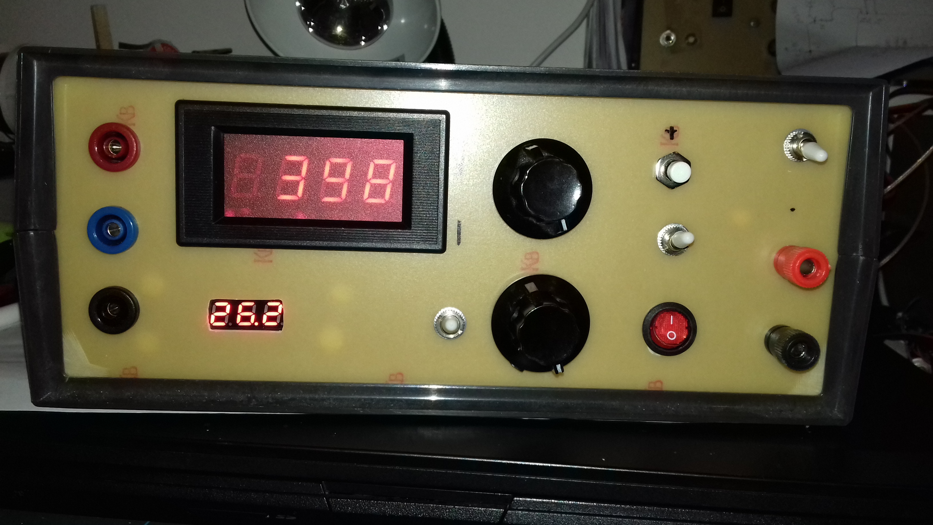
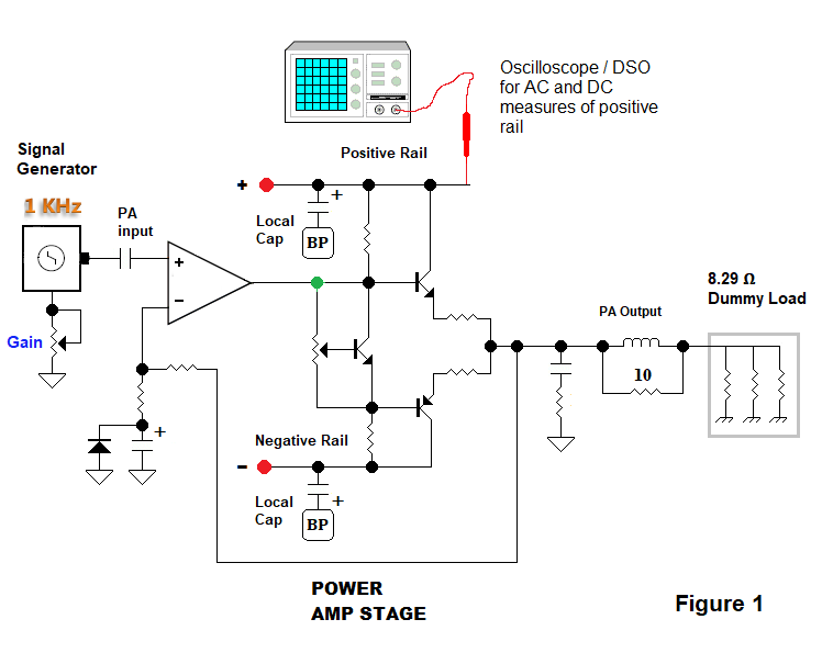
Above — A simple bench setup to measure AC + DC voltages on either of the DC supply rails. I'll use this to measure my positive DC rail voltages -- and later, peak-peak voltages [ AC ripple voltages ] on the positive rail.
Above — DC measure of the positive rail of my power supply that's connected as shown in Figure 1. The signal generator is switched off, or to 0 output. The unloaded positive rail measures + 27.1 VDC.
Above — DC measure of the power supply when connected to a PA driven to maximum clean signal power [ 23W ] by the 1 KHz signal generator.
The unregulated positive rail has sagged to 23.1 VDC under this heavy load. We'll use the above measure when we calculate % ripple in Section E. Reservoir Capacitors and Ripple.
You can't just casually order a transformer like you would some power resistors. Also, the cost may shock you; especially if you live in Canada. Making a power supply takes some thought & planning. Think about your transformer's VA, weight, mounting requirements, RMS AC output voltage, what maximum peak - peak signal voltage, you seek, plus other factors such as whether or not you plan to put the power supply right on the amp chassis, or sit it on the floor of a combo amp with patch wires connecting the power supply to DC power rails.
As you go up in amplifier power rating & apply bigger transformers that provide a larger split DC voltage with more current, your build increases in difficulty. Heat sinking requirements, I squared R losses, the need for thermal protection/current limitation circuitry -- and the potential for unwanted noises all go up. This is especially true if you wish to drive a 4 Ω load.
No one showed me how to make a solid state guitar amplifier, that's why my blog
needs to be taken with a grain of salt. Experts and critics may just
lurk and smirk — however, I welcome constructive criticism from any readers who
know more than I. We all learn that way.
That's why I chose a roughly 23W into 8 Ω clean guitar amp for my first build. Keeping the power down hopefully will allow us to enjoy success in order build confidence, plus gain the skills we might apply to future higher power amps if so desired. C. Schematic
Above — Power supply schematic. For this project, I used the center-tapped Torel toroidal transformer that was listed as 50VA with + 18, 0, and -18 VAC RMS output. Mine measured 20 VAC peak -- and rectified + filtered under load, I get a nominal +/- 25 VDC output. The panel mounted fuse is connected to the hot polarized AC Mains plug. This power supply gets used in all experiments shown on this blog page.
Above — Measuring the positive DC rail with no load on a DVM. I built my power supply enclosure from 2 - sided copper clad board. The lid is off for testing and photography. Although toroidal transformers leak less magnetic flux than conventional frame types, they still require electrostatic shielding to prevent capacitive coupling to nearby circuitry. Sometimes moving or rotating them may reduce their hum field. In general, keep you power supply away from your signal path circuitry; and especially your pre-amplifier.
If you consider the wires that lead to and from the transformer, the rectifier diodes and the reservoir capacitors as a loop — the smaller the loop area, the better for EMI prevention. A loop potentially may inductively couple the transformer pulse currents into your nearby circuitry causing an annoying background AF buzzing noise that cannot be filtered off with bypass capacitors.
I'll go through the circuit starting with the Mains AC supply.
Years ago — for anything I make that uses AC mains electricity. I switched to only using an IEC320 C14 receptacle — plus a cord containing an IEC320 C13 appliance plug on 1 end, and a grounded NEMA 5-15P polarized plug at the other Since they're commonly used on personal computers in North America, you seemingly can always find a cord if you forget or misplace one.
Above — Another view of the power supply with the cover off. The IEC320 C14 receptacle contains a 10 amp DPDT switch. The 2-sided copper board is well soldered on both sides so it's technically RF tight around the transformer and mechanically solid to strongly support the AC receptacle and fuse.
Above — The IEC320 C14 receptacle with DPDT switch & the toroidal transformer mounting hardware.
D. In Rush Current
When you turn on and energize a power transformer, an instantaneous surge of current gets drawn to charge up the reservoir caps and to magnetize the transformer. The magnitude of the in rush current is not related to the amplifier load, rather it's dependent on the point in the Mains AC wave cycle when the transformer is switched on.
On the (low resistance) primary coil side this puts potential strain on your switch and fuse -- some larger toroidal transformers will even snap off a house circuit breaker the odd time. Thus ensure you use a slow blow panel fuse, plus a well rated switch. For example, I used a 10 amp @120 VAC rated switch. Perhaps overkill for a small guitar amp, but you get the picture.
On the transformer secondary coil side, your rectifier diodes and reservoir caps get strained during any start up surge. Any rectifier diodes must be tough. I initially purchased a commercial 25 Amp rated diode ring that featured a heat sink and mounting hole. Sadly, this part tested defective. I looked in my rectifier parts drawer and saw about 40 Vishay brand 1N5822 3A Schottky barrier rectifier diodes and then studied their datasheet online. These should well handle my voltage, current needs and any brief inrush surge. They work well for my particular guitar amp. I have no idea when, or who I bought them from however.
I put a slow-blow fuse on each AC secondary to keep the transformer alive should the diode ring ever go shunt to ground. Currently, I've got a 2 Amp slow blow fuse in each slot. The X capacitors are to bypass any HF noise created by the switching diodes from going into the house wiring.
I used hulky capacitors because in the presence of AC bias, some small size ceramic caps may not hold their capacitance value. These 1 kV caps are cheap and easy to find. Carefully check the datasheets for any parts you place in your power supply and consider avoiding 'no - name' parts. It's really sad when you fry a $50 transformer because you decided to save 50 cents by plying a, cheap no-name, part.
Above — The improvised diode ring. I'll shorten the wires even more. Sadly, I misplaced my 0.01 µF/ 1kV X capacitors and had to order more. No doubt, I'll locate them the day the fresh capacitors arrive. I'll shorten the diode ring wires when I install those X capacitors.
E. Reservoir Capacitors and Ripple
The main question we all ask — how big should my reservoir capacitors be? Professor Ken Kuhn wrote a great pdf document for his students. Click here
I consider this document essential reading. Also check out his fantastic web site.
Some audiophiles get carried away with 'requiring" ultra low ripple at high power. From Ken's article, consider aiming for medium to low ripple and use the smallest capacitance that will achieve that goal. Higher capacitance increase surge current as Ken mentioned in his article. More capacitor = more dollars too!
Ripple is a nuanced number that's conditional and contextual. DC supply ripple increases in tandem with PA stage current draw. So ripple could be quoted with no power supply load, with the amp at 1/2 power, full power and so on. For a clean jazz guitar amplifier, the best case seems to be with no applied test signal and the worst case occurs when you apply the maximum test signal before the amplifier sine wave distorts. This is often quoted as the maximum signal drive where amplifier THD is under 1%.
On the web, you'll find a number of write ups and videos how to calculate percent ripple, or, the reservoir capacitor value you need to get a certain percentage ripple. Sometimes they lack precision and seem a bit theoretical. We amp builders need a practical, measurement-based way to evaluate ripple. I'll show some simple oscilloscope measurements and apply Professor Kuhn's formula below. It seems to work OK. It's also fun to actually view the ripple on your DC rails with various reservoir capacitor values and power supply loads. Visceral stuff.
Above — The formula taken from Professor Kuhn's document. To get data to calculate, you'll need a power supply, a signal generator, a PA stage, a dummy load and a oscilloscope or DSO. I've already shown how to measure rail DC with a 'scope DC coupled to your rail earlier in Figure 1. Again, I'll only show the positive rail.
I place additional ripple filtration capacitors on both my pre-amplifier and PA boards. We'll only consider the PA board. As shown in my power supply schematic, my main reservoir caps are 6800 µF. On my PA board lie additional capacitors and on my test 23 W power amplifier, I've got a 2200 µF /50 volt electrolytic capacitor on each of the DC supply rails. So per rail, that's a total of 9000 µF.
Above — DSO screen capture with an AC coupled 10X probe on the positive rail with no applied signal drive. This would be the "best case ripple", but seems totally unrealistic as the PA is drawing only 16 - 20 mA quiescent PA bias current from the power supply.
Above — A DSO capture of the AC signal on my positive DC rail using an AC-coupled 10X probe. The V peak-peak = 660 mV. This is 'worst case' ripple as my PA is drawing maximum current; a heavy load for the DC power supply.
Using Ken's formula, let's calculate the percent ripple from the data we've gleaned.
Ripple = 100 * RMS Ripple Voltage / Average DC Voltage
Your DSO may calculate and display the RMS ripple voltage, however, let's assume you've got a 25 year old oscilloscope with no math functions. We might simply just estimate RMS ripple voltage by taking the measured V peak-peak value and dividing it by 3. We bring the 'worst case' DC voltage from the earlier DC measurement of the positive PA rail.
Ripple = 100 * (0.66 / 3) / 23.1 = 0.952%.
On a popular (but unnamed) jazz guitar amp I recently measured, the AC ripple signal was around 2 V peak-peak with maximum clean drive signal into a 8 Ω resistive load. So I did OK.
This simple method allows you to measure and crudely calculate ripple percentage to make comparisons with different capacitors in real time. So my 9000 µF of C in a low-power jazz guitar amp ranks as ultra-low ripple at 'worst case'. Of course, if you go for a 4 Ω load, it could be a game changer. More on that in Part 2 of this series.
Above — My 2 main reservoir capacitors. Installing them proved a little time consuming. I built my power supply using Ugly Construction on 2-side copper clad board. Since you can only solder their short, thick leads on the bottom side of the main circuit board, I had to improvise. I cut Cu islands for the DC rails and O volt pathways on the top side.
I also had to cut islands on the bottom side of the Cu board. I connected the positive, negative and 0V top islands to their respective capacitor leads below by joining the top and bottom carved islands with via wires. I drilled 5 via holes for each lead and soldered 20 gauge solid copper wire to join each appropriate top and bottom island. I'm used to doing this to provide a low impedance ground in UHF circuits, so it's not a big deal for me. After final testing with an ohmmeter, the 6800 µF caps were installed. I did the soldering with my 80W iron.
I installed the filter capacitors by drilling 1 hole for each cap lead into each of appropriate carved islands and then soldered each capacitor lead to the bottom copper board.
F: Power Supply, Signal and Filter Capacitor Grounding Scheme
We ought to consider ground loop hum and reduce it by carefully placing our parts, rails and various types of ground wires to avoid contaminating our signal ground with charging currents from filter capacitors and other unwanted AC currents. You'll also need a scheme to connect your signal ground to chassis ground plus Earth.
A stellar reference for this topic and also my entire project = Audio Power Amplifier Design by Douglas Self . I can't recommend this book enough. Click for Doug Self's web site
Doug Self's practical knowledge, writing skills and published experiment results provide game-changing insight into the world of audio design from small signal to PA stages.
Above — Grounding scheme. We've got multiple ground terms which gets confusing. On the power supply circuit board lies Reservoir Ground. Reservoir Ground is the 0 volt rail on the power supply and it's only connected to the transformer center tap and 1 node of each reservoir capacitor. Lots of pulsating charge current flowing here.
Signal, and Electrolytic Capacitor 0 Volt Grounds on any circuit boards are connected to the Reservoir Ground by wires. I made a tee off the Reservoir Ground rail and put an Electrolytic Capacitor Ground point at 1 end — and the Signal Ground point at the other end of this tee.
This separates pulsing capacitor charging currents from Signal Ground — and by way of the tee, keeps these 2 points confined away from the 2 main reservoir capacitors. Connecting Signal Grounds to 1 point on the Reservoir Ground rail by wires is commonly called star grounding.
Apart
from the power supply board, most circuit boards will have only Signal
Ground, or Electrolytic Capacitor Ground.
Signal Ground on any circuit board gets connected to the Star Point on the power supply board by a wire as shown.
Grind away any copper on the power supply, pre-amplifier, PA or any auxiliary circuit boards that your circuit board anchoring hardware passes through. This prevents you from connecting any type of circuit board ground to the chassis through any bolts, spacers, washers and nuts used to mount your various boards to the chassis.
In essence, the circuit boards are "floating" from the chassis. They won't truly be floating since we'll connect these boards to the chassis by a special means that's described later.
Consider the DC rails on the PA and pre-amplifier boards. At the
beginning of each positive and negative DC rail lies electrolytic
capacitor(s) that connect to a small 0 volt rail (Electrolytic Capacitor
Ground) that is separate from the Signal Ground on each board. On my
boards, I carve out a small island for the Electrolytic Capacitor Ground
rail. Run a copper wire from each Electrolytic Capacitor Ground island
back to it's proper grounding point on the power supply board as shown.
Auxiliary board 0 Volt
ground returns such as those that contain relays, thermal, or non-signal support circuitry get
connected to the their own special tee to Reservoir Ground on the power supply circuit board by a
copper wire. See the diagram.
Mains ground from now on is called EARTH. EARTH is the AC ground lug of the IEC320 C14 receptacle. Connect a thick, shielded copper wire from this EARTH lug to the guitar amplifier input jack ground lug. Thus, the amplifier input is EARTHED by this wire.
The 2 - sided copper clad board surrounding my transformer is also connected to EARTH lug of the IEC320 C14 receptacle. Since my power supply shielding box is "floating" from the chassis it will only be connected to the chassis by way of the single wire mentioned above.
Signal Ground is connected to Chassis Ground at 1 point. Some designers do this with a 10 Ω resistor. For example, you'll see this in the Fender Jazzmaster Ultralight guitar amplifier schematic.
Another way, I learned about from Doug Self, is through a shielded input cable from the guitar amplifier input jack to the first pre-amplifier stage.
The 1/4 inch guitar amp input jack's grounded sleeve body is usually automatically connected to the metal chassis because it's a conductor. Check it with an ohmmeter. If you use a plastic 1/4 inch amp input jack, you'll have to connect its ground lug with a short wire to a bolt on the chassis. Whatever you do, ensure you've got a solid, low impedance connection to the chassis from the amplifier input jack's ground node.
The ground braid or shield of the proximal input coaxial cable gets connected to the guitar input jack ground lug. However, recall that the jack ground lug ( and chassis ) is also EARTHED through a wire at exactly this point — providing strong ground loop immunity.
The distal end of the coaxial cable goes to your pre-amplifier input stage. The braid at this end goes to the star grounding point on the power supply circuit board as shown. So you now have connected your EARTH, Chassis and Signal Grounds to the Reservoir Ground in a manner which helps reduce grounds loops.
G. Regulated DC for Your Pre-Amplifier Board
To garner maximum headroom, it's desirable to run op-amps like the NE5532 and/or TL072 with more DC voltage than the doldrum standard of +/- 15 VDC. You might go as high as 17 volts on the rails. Since, I've got an abundance of 16 volt zener diodes on hand, I opted to build my rail voltage regulators around these. The 17V 1N5247B zener diode might also prove a good choice.
Many builders just run linear regulators and adjust the rail voltages to somewhere between 15 and 17 VDC.
I chose the field-tested emitter-follower configured DC regulator with a gain of 1. The base-emitter voltage drop of this topology lays in series with the load, so load current changes will alter the regulator output voltage. Vout = V Zener – VBE: so the regulated voltage will be under 16 volts if you apply a 16 volt zener diode. Barring catastrophe, once the pre-amplifier board is connected, the DC voltages on each rail will hold steady.
The BJT base bypass capacitor value gets roughly multiplied by the transistor's current gain which boosts low-pass filtration of the stage to further scrub down rail ripple. The electrolytic capacitor and zener diodes 0V leads go to Electrolytic Capacitor Ground on the power supply board as discussed earlier.
Above — Pre-amplifier voltage regulators: one for each rail. I added diodes to limit the stage current to a maximum value somewhere above 200 mA. One diode compensates for the BE junction of the transistor, while the second diode limits the voltage across the emitter resistor to the diode ON voltage ( around 0.6 V ).
I'll show the actual capacitor values + my DC measures on the pre-amplifier boards later in this series of blog posts.
H. Output Rail Notes
Above — Power Amp Output Rail diagram. This isn't really about the power supply circuitry, however, I don't know where else to put it. Your PA output rail receives all of the amplifier's power and some serious current is flowing here. Authors such as Doug Self recommend that we don't connect our 3 PA output rail networks at the emitter connection points. Make a tee as shown and then choose your 3 takeoff points. This confines the PA transistor emitter energy away from these 3 nodes.
This is part 1 of a multiple part series about a scratch home brew guitar amp.