Via AMSAT: ANS-182 AMSAT News Service Weekly Bulletins
30 June 2024 at 20:16
In this edition: * Firefly Aerospace’s Alpha “Noise of Summer” Mission Rescheduled * Curium One...


Direct Conversion Receive System (Video Supplement)
I've built a lot of stages for this video -- but wanted to test a few of the better 50 Ω input Z audio preamps in an actual DC receiver. A functioning direct conversion receiver provides a good way to test for voltage and power amp instability & noises. I also wanted to get a feel for how much gain we really need despite all the mythos about this topic. With this supplement, I won't have to go into too much detail about the test receiver on the video.
My main receiver goal hasn't changed for 25 years — lift desired RF signals out of the ether with a decent signal to noise ratio while listening to a speaker at comfortable room loudness.
 Above — DC receive system. My chassis contains 2 BNC mixer input ports, an SBL-1 diode ring product detector, a post-product detector network and then 3 audio amplifiers plus a speaker jack. The AF amps = a 50 Ω impedance voltage amp, a second voltage amp with an active gain control - and finally a PA. I'll cover each AF stage separately, but first I'll show the complete receive system from inputs to output. Each stage lies on a separate piece of copper clad board. The active stages are numbered 1, 2 and 3. I soldered 2N4401 or 2N4403 for the BJTs.


Above — Schematic of the PA with DC measures. At this point, I did not add the 22 Ω DC decoupling resistor shown in the completed receiver. Few homebrew PA's will oscillate when tested stand-alone with a signal generator into a resistive load. I also took AC measures with my DSO.
A single voltage divider network feeds each of the 2 current sources. A 220 µF capacitor shunts voltage divider noise to ground.
My readers/audience asked me to make a single DC supply audio PA only using TO-92 transistors as finals.This is it. I worked hard to find a solution where the maximum output transfer function would compare with the venerable LM386 -- and bonus -- this final transistor pair tend to not suffer thermal runaway and smoke up your lab.
The key design features to get those goals included serious degenerative feedback [ 68 + 39 + 1 Ω resistors ], plus current sources to drive the input pair and VAS/final base bias stack. I also set the voltage gain to 21. By increasing the the 2K7 feedback resistor, higher gain lies on tap (a voltage gain of 80 or more arises with a higher feedback resistor); however, this is a power amp and not a voltage amp. Low noise best practices suggest you build up your AF signal voltages with low-noise voltage amps and not within the PA stage.
Above — A close up of the PA in-situ. A temporary orange coloured 1 µF metalized poly film cap lies at ~ 6 o'clock. I connected either a 1 KHz tone or a CD player to the PA via this capacitor. I listened to this PA with my CD player for 4 nights and it sounded lovely & crisp. I built 2 separate PA stages to ensure my design worked. Although preferable, I did not match the input emitter-coupled pair.
Perhaps foolishly -- I did not place heat sinks on my final complimentary pair. All the base drive current comes from the current source and not the usual complimentary pair that drives the finals. Thus they do not run as hot as any other decently designed TO-92 stages I've built.


Above — An FFT of the PA driven to 697 mW with a ~ 1 KHz tone. Pretty good results from a single 2N4401/2N4403 emitter follower pair.
PA Instability
Once you connect all your AF stages together in a DC receiver, unwanted audio oscillations may occur.
This might be motor boating — a pulsed, typically low frequency oscillation that may even vary in amplitude and cause squegging. In addition to motor boating -- a steady, higher frequency oscillation tone that sounds hollow "or howls" may arise -- this usually occurs at loud volume.
I learned to think of your DC supply line as a highway connecting various stage inputs to outputs throughout your audio chain. Decoupling the DC line with series resistors and bypassing with AF and sometimes RF capacitors shunt to ground helps to stop AC signals from travelling along this highway. The ultimate way might be to use a capacitive multiplier BJT as shown on the first preamp labelled "one". The capacitor value connected to the base gets multiplied by the Beta of the transistor which sets a long time constant for very low frequency oscillations and those above this low corner frequency.
For motor boating, I normally place a 10-22 Ω decoupling resistor and
both a RF and AF bypass capacitor on the PA DC line. I suggest a 470-1000 µF for
the DC audio bypass capacitor as a minimum starting value. Each stage in
your DC receiver should get some low pass filtration with such an RC
network to keep AC signals from travelling down the DC highway.
Further, AF & HF oscillations may also occur in your PA voltage amp called the "VAS".
AF/RF oscillations also require low-pass filtration, but often just a local bypass capacitor alone will do the job. My PA emitted a ~ 800 Hz howling sound when the volume was turned up loudly. I tamed this by soldering a 270 pF MLCC RF cap from the emitter shunt to ground. For my guitar amps, I've had to apply other strategies.

Above — Ways to tame audio oscillations in a PA. The emitter degeneration resistor R1 could be increased to lower VAS gain. For example, from 39 to 47 Ω . And/or the C1 value could be increased to get the best result at high drive into the PA. This testing will annoy your family if you listen through a speaker like me! The VAS serves as the main PA voltage amp and offers a big source of instability in some PA designs.

Above — Additional circuitry I've used to tame a 40W guitar amp PA that oscillated at higher drive levels from AF to RF: 100 pF cap from collector to ground. then a 10 Ω resistor on the VAS collector with a RF bypass cap on each base followed by a series R at the BJT base terminal.
Interestingly in this DC receiver PA build, adding a Zobel network did nothing measurable, so I left it off. I've also connected the VAS base to ground via a series RC network. Sometimes, it's trial and error.
Voltage Amplifier with Active Gain Control

Above — The first version of the inverting active gain control stage. In my reference receiver, I employed the other half of the NE5532 as a follower/buffer. Technically, you do not have to use a buffer, but it helps isolate the active gain stage from the PA input. I've built other active gain control circuits that offer a better log response of the volume control, but this version seems simpler. If you need more maximum gain, drop R1 to 560 or 470 Ω etc..


![]()
Thank you to RTL-SDR.COM reader Lee. who found a recently released program called "gypsum" which enables an RTL-SDR or HackRF to be used as a GPS Receiver when combined with a GPS antenna. Phillip Tennen, the author of Gypsum notes that Gypsum can obtain a fix within 60 seconds from a cold start and that it has no dependencies apart from numpy. We want to note that it appears that Gpysum has no live decoding ability yet, as it works from pre-recorded GNU Radio IQ files.
In the past, we've shown in a tutorial how GPS can be received and decoded with GNSS-SDRLIB and RTKLIB on Windows. The new Gypsum software should work on Linux and MacOS too.
What's more, Phillip has written an incredible 4-part writeup on how Gypsum was implemented from scratch. In the write-up, Phillip introduces GPS and explains how it can even work with such weak signals that appear below the thermal noise floor. He then goes on to explain how the detected signal is decoded and turned into positional information, and how challenging it was to propagate the accurate timing information that calculating a solution requires. The write-up is presented with clear visualizations to help readers intuitively gain an understanding of the advanced concepts involved.
![]()
If you are looking for a portable and easy-to-use HF vertical antenna, then the Chelegance MC-750 Portable HF Vertical Antenna system is worth considering. These antennas are designed to provide quick and effortless setup without requiring tools, making it ideal for field operations and emergency services.
The MC-750 Portable HF Vertical Antenna is built to provide an efficient quarter-wave vertical ground plane antenna for 40 through 6 meters. It can handle up to 100 watts and features a female SO-239 connector and jacks for up to 4 preassembled, 11.48 ft. counterpoise radials. Additionally, the antenna comes with a 7 MHz loading coil, 1.64 ft. extension, 17 ft. telescopic whip, and a cable winder, all packed in a carrying bag for easy portability.
The Chelegance MC-750 Portable HF Vertical Antenna provides a hassle-free setup process. The antenna offers good efficiency for a compromised portable ground based antenna. The telescoping whip and preassembled radials make it easy to get on the air quickly, while the included carrying bag makes it easy to pack and transport.
Setting up the MC-750 is simple and straightforward. First, unpack the kit and extend the telescoping whip to its full length. Next, attach the 7 MHz loading coil to the base of the antenna and connect the antenna to your radio using a coaxial cable with a PL-259 connector. Finally, lay out the preassembled radials on the ground in a star pattern, ensuring that they are evenly spaced, and connect them to the antenna base.
Q: How does the Chelegance MC-750 Portable HF Vertical Antennas perform on different bands?
A: The MC-750 is designed to operate on the 40 (with loading coil) through 6 meter bands.
Q: What is the maximum power handling capacity of the MC-750?
A: The MC-750 can handle up to 100 watts of power.
https://www.dxengineering.com/parts/nce-ch0010009
The Chelegance JNCRadio MC-750 portable HF antenna, is a good choice for portable or emergency use. It is easy to set up and comes in a compact well designed case for easy transport. The reference marks etched into the antenna sections make it easy to get the SWR in the ballpark,
Note that the antenna base/spike does not use the standard 3/8×24 mount. The base uses a metric M-10-1.5 thread so other antenna systems like the MFJ-1979 would require some type of adapter.
In terms of performance, the Chelegance MC-750 is a reliable ground-based vertical antenna that provides decent RX and TX capabilities for the 20 meter band and up. The 40 meter loading coil is a compromise at best but will get you on 40 meters. The Chelegance MC-750 is a good option for situations where no trees are available or quick activations are in mind.
![]()
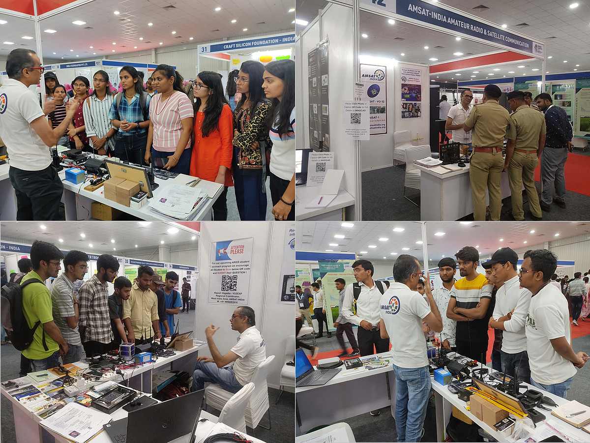
Engineering Students were among the visitors to the stand
To celebrate National Science Day of India on February 28 one of the biggest Science Carnival 2023 was organised by Gujarat state – India at prestigious Science City Ahmedabad during 28th February to 4th March 2023.
AMSAT-INDIA was specially invited to participate in this biggest scientific exhibition for mass awareness on Amateur Radio & Satellite Communication!
AMSAT-INDIA Regional Coordinator Rajesh Vagadia VU2EXP & team member Sakshi Vagadia VU3EXP did huge efforts to mass promote AMSAT activities amongst all sort of visitors which includes young kids, school-college students, budding engineers, IT Programmers, general public, professionals from various industries, scientists from renowned organization like ISRO, PRL, IPR, VSSE, ISR, officers from BSF, Police, Fire dept and citizens from every walk of life! More than 100,000 visitors were reported and grabbed the opportunity to visit science carnival 2023 and our Science exhibition during 5 days.
AMSAT-INDIA stall was spacious & decent sized at 3m x 3m, it was a big attraction at the center of the Science Exhibition. With well prepared different informative Banners on AMSAT-INDIA, Various Satellite Activities, Amateur Radio Satellite chronology, ARISS Student outreach program, ARISS SSTV event, Question submission for our upcoming ARISS student outreach program etc was absolutely eye catching from a distance.
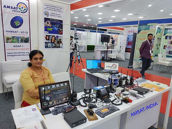
Kiran on the AMSAT-India stand
For the curious visitors we tried to highlight every aspect of our hobby and exhibited all sorts of Radio stuff, Documents, QSL Cards, Books, Ham Licence, Awards, Project articles, Tracking software, SSTV software, SDR Software, Cube Satellite models etc to give bit idea of our hobby.
Experiencing various amateur radio gears, satellite antenna & test instruments were highly appreciated by visiting budding engineers from a number of colleges at AMSAT-INDIA stall. Some of the stuff we displayed include; Dual band Arrow-II antenna, dual band Yagi, tape measure antenna, GP, Telescopic antenna for SDR, Radios includes Icom IC-705 with LiFePO4 battery pack, Kenwood VHF base, half dozen of VHF/UHF HTs, RTL-SDR setup, LDG ATU, NanoVNA, Morse Key, cw oscillator, Paddle, electronic keyer, SWR/Power meter, Cable, Connectors etc. It made our task easy to explain the use of each stuff according to the visitors’ query.
We came across various types of queries like how to be a Ham, Procedure to get license, Types of Amateur Radio satellites, operating modes, setting up ground station, how to receive ISS SSTV images, how to establish satellite contact etc. We made a humble attempt to answer & satisfy all of those queries. We enjoyed a very detailed discussion with students/groups who already know about Amateur Radio and always need to learn more on Satellite Communication.
We also highlighted contributions of worldwide AMSAT organizations, IARU, ARISS, RSGB, ARRL and our ARSI & GIAR. I also mark a note on an author and my teacher Mr. Nagendra Vijay of popular Gujarati Science magazine named ‘Scope’ who did tremendous efforts to introduce Ham Radio in Gujarat (India) 40 years back and still continue to create awareness via it’s leading Science magazine ‘Safari’, his stall was just after a row.
Our AMSAT-INDIA stall were visited by many well-wisher GIAR Ham friends including VU2CPV Pravinbhai, VU2JGI Jagdishbhai, VU2MJP Manojbhai, VU2SPF Bhatnagarji, VU3APY Asheshbhai, VU3VDC Vitthhalbhai, VU3GLY Priyesh, VU3WHO Snehal etc.
It was a great experience for us to spend the whole 5 days enjoying talking & explaining our favorite hobby Amateur Radio & Satellite Communication!
We were happy to present amateur radio as a scientific hobby & experimenting platform for diversified fields and not just emergency communication tools!
Lots of positive & appreciating feedback we received in the visitor feedback book.
We are thankful to Science Carnival 2023 Organiser Dr. Vrajesh Parikh, Pulkesh Prajapati, Dr. Narotam Sahoo & team for inviting us for this prestigious Science Carnival Exhibition. I also thank our AMSAT-INDIA Secretary Mr Nitin Muttin VU3TYG, Director Educational B. A. Subramani VU2WMY, President Ramesh Ramsubbu VU2RMS & committee for complete guidance and support extended to us.
I specially thank team member Sakshi Vagadia VU3EXP & my XYL Kiran Vagadia for supporting and assisting me all the time during the 5 day exhibition.
I am optimistic to see the next generation taking keen interest in Amateur Radio & Satellites from VU Land.
Thank you
73 Rajesh Vagadia VU2EXP
Rajkot – Gujarat
Regional Coordinator West India Zone, AMSAT-INDIA
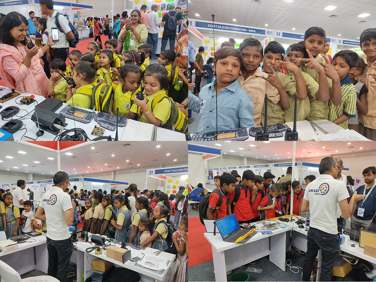
Many youngsters visited the stand
![]()
In the midst of a global pandemic, classroom learning continues. This is a story about a high school physics class continuing to operate and expand its horizons through exposure to the magic of amateur radio satellites – even while taking on the challenges of social distancing.
About two weeks ago, one of my neighbors asked me if I could help some students contact the International Space Station (ISS) via ham radio as part of a Physics project for school. I thought, “Wow! What a great opportunity. It’s a big goal, but, if possible, I’d love to help them make this happen.”
I met with the three high school freshman immediately via Zoom to hear more about what they wanted to do. They had just completed a Physics unit on orbital mechanics and their final assignment was to find a practical way to experience what they had learned. But, when they told me that they needed to get the project done in about five days, I gently explained the issues of worldwide demand, limited availability of astronaut time and complexity in setting up a school contact with the ISS via amateur radio. They quickly understood that while possible, making one happen in just a few days would be impractical. They were slightly disappointed.
There had to be a way to help the students experience the phenomenon of orbital motion. If we focused on the ISS, we could hope for a pass over our area and actually see the satellite as it crosses the night sky. But, would there be a good enough pass over the next few days? Would weather cooperate? How could we arrange this while still observing social distancing? Too many what-if’s. We needed a different approach.

So, I offered them the opportunity to learn about and experience communications using amateur radio satellites – an alternative that would allow them to achieve almost everything they wanted to accomplish. When they heard the idea, their enthusiasm rebounded immediately.
So, we started to get ourselves educated on amateur radio satellites. I directed them to some helpful web resources:

Meanwhile, my home satellite station hasn’t been running for a while. Two years ago, while I was setting up computer control of my Az-El rotor, the rotor failed – permanently. That, unfortunately, sidelined the project. So, I had to come up with something quickly to satisfy the needs of this new project. I dug out my trusty Yaesu FT-847 and connected it to SatPC32 pass prediction software running on a laptop and a dual-band vertical at 20 feet, just to see if I could hear any of the amateur satellites. Good news! They weren’t pinning the S-meter, but I was hearing several of the active satellites – SO-50, AO-73 (FUNcube-1) and the XW-2 satellites. Beacons and some QSOs were audible. Things seemed better on 2m downlink than 70cm.

I got back to the students and let them know that it would be possible to hear these satellites. Then we got to talking about their learning objectives. The goal was to get some hands-on experience with orbital motion. How could we accomplish that with an invisible amateur radio satellite?
First, we walked through the SATPC32 pass prediction software. We looked at the views of earth and the paths the satellites were taking as they orbited the globe. We discussed the concept of a visibility footprint. Then, an idea came to mind. I asked the girls if they had learned about the Doppler Effect in their Physics class. It turns out that they had been exposed to the concept earlier in the year – and the examples they studied were all in the audio realm. When I told them that the radio transmissions to and from a satellite would be affected by Doppler, they were interested. So, we set a goal to observe Doppler as we listened to transmissions from an amateur radio satellite.
Video conferencing has truly come of age in recent months. Previously used primarily by businesses and tech-savvy individuals, virtual meeting technology – driven by pandemic restrictions – has become the communication tool of choice for all of us – from the most to the least technically-oriented. And, the Zoom service has emerged as one of the most effective implementations for consumer use. The students were well-versed in the use of Zoom . . . and virtual conferencing and collaboration technology has been my business for 30 years . . . so it was easy to jump right into using Zoom meetings to keep our project on track.
I provided several references to help them get a basic understanding of Doppler in the context of satellite-based communication systems.
After reviewing the reference material and doing some research on their own, we got together on Zoom to discuss and observe the Doppler shift, in a real satellite communication system.
We listened to the XW-2A satellite as it went overhead. The beacon shifted frequency, as we predicted.
As the XW-2A satellite continued its journey across the sky, we noted that the beacon was quite strong. We wondered if we would be able to hear stations making contact through the satellite. As we scanned the satellite downlink frequency range, we found a station making a general call – looking for a contact. We replied to his call . . . and he responded!
Our contact with Don, callsign AK2S, lasted only about 2 minutes, as the satellite was rapidly nearing the horizon. But, it was quite a success – more than we had expected to be able to accomplish with the limited time and antenna system available to us.


The post Amateur Radio Meets STEM in Pandemic-Challenged Virtual Classroom appeared first on The Driven Element.