via Hackaday: Revisiting 1990’s Mac Games That Never Were
3 October 2024 at 16:45

Up until now I have been running 3 Raspberry Pi 4 systems all held in a metal frame with fans which makes a nice neat setup. One Pi does the home automation, one runs pi-hole (really useful!), and one is a server and has an SSD attached. Not long ago while we were out of the country (of course) the website hosted by the server failed. I did not have remote ssh access set up nor a VPN for access. When we got back home the pi had lost the filesystem on the SSD. The disk was still mounted, but not accessible. Being a server all logging was on the SSD so no errors were caught. A reboot was the only way to cure it.
I thought it was a one off until it happened again, this time while I was nearby. After that our broadband was upgraded to FTTP and with PlusNet giving a fixed IP and no blocks I moved my production websites and email server across to the Pi, saving the rental of the VPS I had been using up until then. The cost of the VPS covered the annual cost of the broadband so worked out well.
Then the Pi lost the SSD twice in three days. This time had got worse because on reboot it did not start Apache or fail2ban, even though they both started fine by hand once I had realised. So something is wrong in the setup and I cannot find out what.
So I pressed an old Lenovo miniPC into action and rebuilt the server onto it. One thing I learned ages ago was to document everything that goes onto the server (and indeed all my other systems) so I can simply run through the list, add everything back in and copy /home across. Relatively QED.
But this time round something caught me out. After everything was moved across to the Lenovo and IP addresses swapped so it became the server web access was still going to the Pi. It transpired that the PlusNet broadband router associates the port forwarding with a physical device, not a IP address. Easy enough to sort out via web access to the broadband hub, but one more thing to remember (and duly documented!)
In 1985, I built a home-brew decoder and experimented with RTTY, but I never got it to work. I've since decided that I didn't know how to tune RTTY properly. Things changed in 2005 when I downloaded CocoaModem made my first RTTY contacts.
Since I was involved in contesting, I naturally turned to RTTY contesting. Today, it is unusual to hear RTTY signals on the bands except during contests. Thirty or more years ago, RTTY was commonly heard on 80 and 20m.
For effective RTTY contest communication, several principles apply.
{TX}{ENTERLF}{MYCALL} {MYCALL} {RX}
or
{TX}{ENTERLF}* * {RX}
(For N1MM, the asterisk and {MYCALL} macros are the same)
Notice the message starts with {TX}, performs a carriage return / line feed with {ENTERLF}, sends the call twice, ends with a space and then {RX} to go back to receive. Sending the call twice helps to ensure the recipient receives it correctly.
If you are lucky enough to get a response, you'll have to send the exchange. The exchange will vary by contest, but it could be a message like this:
{TX}{ENTERLF}! 599 GA GA DE {MYCALL} {RX}
This is what I send in the RTTY Roundup. First is the recipient's call (!). Then 599 -- don't use 5NN, because that actually takes longer to send in RTTY -- and send it only once, because it isn't important. Then the exchange is sent twice, followed by the prosign DE and my call, followed by a space.
N1MM's authors recommend you use the ! character rather than the {CALL} macro. The reason is that {CALL} isn't subject to correction -- it sends the contents of the Call field at the start of the message. The ! character will send the Call field as it is being corrected in real time. As a practical matter, most RTTY contest contacts involve pointing and clicking on callsigns, so there's less typing, and therefore fewer corrections involved.
A couple of things here. Notice I did not use the {EXCH} macro above. When there are multiple elements to the exchange, I put the repetitions together. So, I tend put the exchange information into the macro directly. For example, here's an S & P exchange for CQWW RTTY:
{TX}{ENTERLF}! 599 GA GA 5 5 DE {MYCALL} {RX}
GA for Georgia, and 5 for zone 5. For NAQP RTTY, it would be:
{TX}{ENTERLF}! 599 BILL BILL GA GA DE {MYCALL} {RX}
Some might balk at the use of the DE prosign, particularly for exchanges that involve a state or section, since DE might be confused with Delaware. However, I think this prosign is useful, as it establishes the callsign is of the answering station, and not the CQing station.
{TX}{ENTERLF}CQ RU {MYCALL} {MYCALL} CQ {RX}
Note that the important information -- the callsign -- is repeated. The other curious thing is the "CQ" at the end. This indicates I finished a CQ message. This is important because one cannot tell when potential callers tune in to your signal. If they do so during the first callsign, the can't tell if you are calling or answering a CQ. Putting "CQ" at the end establishes you are calling CQ. And it is shorter than "QRZ?".
Naturally, one indicates the contest in the CQ message. Here it is "RU" for Round Up. Use whatever is appropriate for the contest, or simply "TEST".
When someone answers your call, you send an exchange message:
{TX}{ENTERLF}! 599 GA GA ! {RX}
Note that the exchange is sent twice, and if there were more than one element to the exchange, I'd send those twice as well:
{TX}{ENTERLF}! 599 BILL BILL GA GA ! {RX}
Another item to notice is there is no {MYCALL} macro in this message. Instead, the caller's callsign (!) is sent twice, once at the beginning and once at the end. There are two reasons for this. First, it follows the principle of sending important information twice. It could be the caller's callsign printed incorrectly to me, or perhaps it will print incorrectly when I send the message back. If I only send the callsign once, the caller might or might not correct it if is wrong, or they may correct it if it printed incorrectly to them.
Unnecessary corrections are a waste of time, but necessary corrections are desired.
Second, it may be that during the response with the exchange, other stations may also be calling. This, creates a good chance that the initial callsign in the response will print incorrectly. If you don't send the callsign again at the end, it could be unclear who you responded to.
Once you've received the exchange from the caller, one sends an acknowledgement:
{TX}{ENTERLF}! TU DE {MYCALL} CQ {RX}
Short and simple. Two features here. One is the DE prosign, to indicate this is the transmitting station's call, and ending with "CQ" to invite new callers.
{TX}{ENTERLF}! TU {LOGTHENGRAB}NOW..{ENTERLF}{F5} 599 GA GA {F5} {RX}
This message omits {MYCALL}, and uses the {LOGTHENGRAB} macro to first log, then grab the callsign off the automatic decode stack, then it follows with the normal exchange. If you use Single Operator Call Stacking, you can use {LOGTHENPOP} instead. See the N1MM manual.
Note that instead of using the exclamation point (!), we use the {F5} macro. Both the exclamation point and the {CALL} macro won't be updated by the {LOGTHENGRAB} macro, but {F5} will.
{TX}{ENTERLF}! 599 BILL GA DE {MYCALL} {RX} -- short S & P exchange
{TX}{ENTERLF}! 599 BILL GA {RX} -- short exchange for S & P or CQing
{TX}{ENTERLF}599 BILL BILL GA GA {RX} -- repeat of just the exchange
{TX}{ENTERLF}CQ RU {MYCALL} CQ {RX} -- short CQ
{TX}{ENTERLF}TU DE {MYCALL} CQ {RX} -- short acknowledgement
All these should be used when you have solid copy, want to get back to other callers quickly, or you are fairly certain the other operator already has your exchange information from a previous contact.
{TX}{ENTERLF}AGN AGN {RX}
Or perhaps you need a fill of one element:
{TX}{ENTERLF}STATE? STATE? {RX}
{TX}{ENTERLF}NR? NR? {RX}
{TX}{ENTERLF}NAME? NAME? {RX}
Before you open up with a CQ on a frequency, this is good one:
{TX}{ENTERLF}QRL? DE {MYCALL} {RX}
Maybe if you are not sure someone is calling you:
{TX}{ENTERLF}QRZ DE {MYCALL} {MYCALL} {RX}
Or the short version:
{TX}{ENTERLF}QRZ DE {MYCALL} {RX}
Every once and a while, directed call is useful, especially when two stations are calling CQ on top of each other:
{TX}{ENTERLF}! DE {MYCALL} {MYCALL} {RX}
Update July 1, 2024. LoTW is back up! It is running slow, but it is available. Thank goodness.
--
When I wrote the article back in May, I hardly thought that LoTW would be down a month later.
Sadly, the outage continues.
My suspicions were correct, however, that this was something more than a simple networking problem. The ARRL has since admitted their network was viciously and uniquely hacked. I can certainly understand their caution to make sure that every system linked to LoTW is given a clean bill of health before turning the system back on.
Earlier this week, on Tuesday there was apparently a brief period of time when LoTW was accessible. A couple of my ham buddies managed to upload some contacts. They'll have to wait for confirmations when the rest of us can get in.
I do hope it is soon. I'm really missing this service.
This article describes a Arduino based thermometer using a 1-wire DS18B20 digital temperature sensor using a SDD1306 or SH1106 OLED display.
The DS18B20 is a digital sensor, used for relative noise immunity, especially given the choice of an OLED display.
This is a basis for tinkering, for modification and a vehicle for learning.
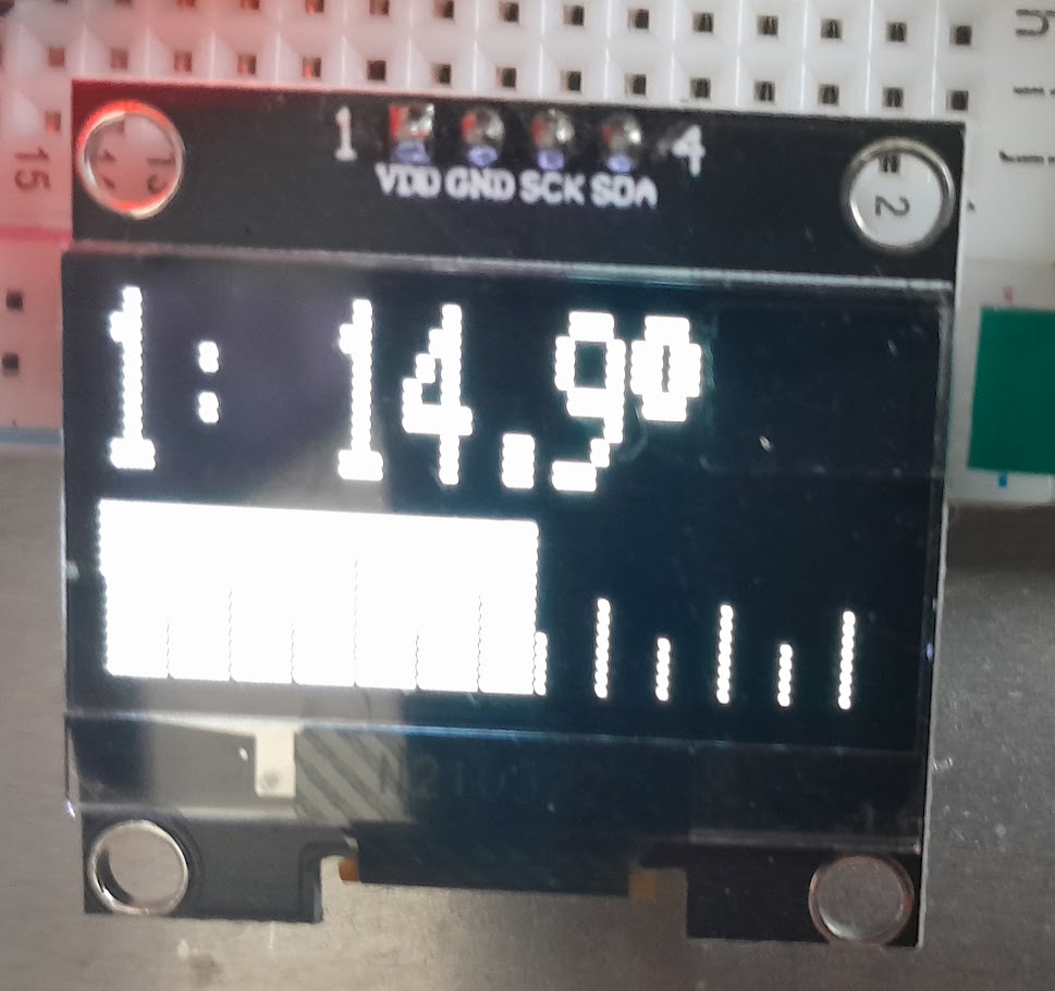
Above is the sample display.
The code is written to support multiple sensors on the 1-wire bus, it cycles through each of the sensors displaying them for 1s each.
The DS18B20 can be connected using a two wire connection and using “parasitic power”.
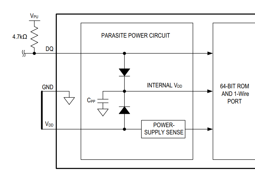
Above is a simple scheme for parasitic power which should work with one master and one sensor at the other end of the cable for tens of metres. For longer cables and multiple sensors, see (Maxim 2014).
Note that the Vdd pin is tied to ground.
![]()
Above is a capture of the DQ line for search and read of a single DS18B20.
![]()
Above is a zoomed in view of the 1-wire encoding format.
![]()
The display uses I2C.
![]()
It takes just under 25ms to paint the display using the example code.
Here is source code that compiles in the Arduino IDE v2.3.2.
#define VERSION "0.02"
#include
#define SCREEN_WIDTH 128 // OLED display width, in pixels
#define SCREEN_HEIGHT 32 // OLED display height, in pixels
#define TEMPMIN -20
#define BARGRAPH
#define PPD 2 //pixels per degree, must be +ve integer
#define TICKMIN 5
#define TICKMAJ 10
#define SSD1306_DISPLAY
//#define SH1106G_DISPLAY
#if defined(SSD1306_DISPLAY)
#define OLED_RESET    -1 // Reset pin # (or -1 if sharing Arduino reset pin)
#include
Adafruit_SSD1306 display=Adafruit_SSD1306(SCREEN_WIDTH, SCREEN_HEIGHT, &Wire, OLED_RESET);
#endif
#if defined(SH1106G_DISPLAY)
#include
#define WHITE SH110X_WHITE
#define BLACK SH110X_BLACK
Adafruit_SH1106G display=Adafruit_SH1106G(SCREEN_WIDTH,SCREEN_HEIGHT,&Wire);
#endif
#include
DS18B20 ds(2);

#if defined(__AVR_ATmega328P__)
HardwareSerial &MySerial=Serial;
#endif

int i;
int barh=SCREEN_HEIGHT/2-2;
int basey=display.height()-1;
int tickh=barh/4;

void setup(){
  float adcref;
  long adcfs;

  #if defined(__AVR_ATmega328P__)
  analogReference(INTERNAL);
  adcref=1.10;
  adcfs=1024;
  #endif
  analogRead(A2); //Read ADC2
  delay (500); // Allow ADC to settle
  float vbat=analogRead(A2); //Read ADC again
  vbat=16*(vbat + 0.5)/(float)adcfs*adcref; //Calculate battery voltage scaled by 150k & 10k
  // Display startup screen
  MySerial.begin(9600);
  MySerial.println(F("Starting..."));
  #if defined(SSD1306_DISPLAY)
  display.begin(SSD1306_SWITCHCAPVCC, 0x3C);  //Initialize with the I2C address 0x3C.
  #endif
  #if defined(SH1106G_DISPLAY)
  display.begin(0x3C, true); // Address 0x3C default
  #endif
  display.setTextColor(WHITE);
  display.clearDisplay();
  display.setTextSize(1);
  display.setCursor(0, 0);
  display.print("DS18B20 thermometer");
  display.setCursor(0, 12);
  display.print("ardds18b20 ver: ");
  display.println(VERSION);
  display.print("vbat: ");
  display.println(vbat,1);
  display.display();
  delay(1000);
}

void loop(){
  int i,j;
  float temp;
  uint8_t id[8];
  char buf[27];

  j=1;
  while (ds.selectNext()){
    //for each sensor
    ds.getAddress(id);
    sprintf(buf," %02X:%02X:%02X:%02X:%02X:%02X:%02X:%02X ",id[0],id[1],id[2],id[3],id[4],id[5],id[6],id[7]);
    temp=(ds.getTempC());
    MySerial.print(j);
    MySerial.print(buf);
    MySerial.print(temp,2);
    MySerial.println(F(" °"));
    display.clearDisplay();
    display.setCursor (0,0);
    display.setTextSize(2);
    display.print(j);
    display.print(F(": "));
    display.print(temp,1);
    display.print((char)247);

    #if defined(BARGRAPH)
    int w=(temp-TEMPMIN)*PPD;
    //draw bar starting from left of screen:
    display.fillRect(0,display.height()-1-barh,w,barh,WHITE);
    display.fillRect(w+1,display.height()-barh-1,display.width()-w,barh,BLACK);
    //draw tick marks
    for(int i=0;i<SCREEN_WIDTH;i=i+PPD*TICKMIN) display.fillRect(i,basey-barh+3*tickh,1,barh-3*tickh,i>w?WHITE:BLACK);
    for(int i=0;i<SCREEN_WIDTH;i=i+PPD*TICKMAJ) display.fillRect(i,basey-barh+2*tickh,1,barh-2*tickh,i>w?WHITE:BLACK);
    if(TEMPMIN<0) display.fillRect((0-TEMPMIN)*PPD,basey-barh+tickh,1,barh-tickh,i>w?WHITE:BLACK);
    #endif

    display.display();
    j++;
    delay(1000);
    }
  delay(100);
  }
This code suits a 128*32 pixel display. Changes will be needed to optimise other display resolution.
See https://github.com/owenduffy/ardds18b20 for code updates.
See https://github.com/owenduffy/tds18b20 for a platformio implementation.
Maxim. 2014. Guidelines for long 1-wire networks.
May 16th, there was an issue with Logbook of The World (LoTW). I could not load the main page at all -- receiving an error indicating the server wasn't responding.
That's pretty normal stuff, actually. There are dozens of problems that can result in this kind of error, so I wasn't surprised. I figured the ARRL staff would address it quickly. But, after much of the day, I was still getting the error.
So, I sent a message to lotw-help@arrl.org, informing them that the web site wasn't responding, kindly asking when they expected it to be back up. I mentioned I was surprised there was no notice of the outage on the ARRL.org web site.
Later that day, the ARRL put up a notice that there was a service disruption involving access to the network, and that it affected LoTW and the ARRL Learning Center. They even updated it the next day, addressing concerns users had over information privacy.
But then, nothing happened. Not until May 22nd, when they updated the notice without really adding any information.
Now, part of this delay may be due to the fact that much of the ARRL staff were all out at the Xenia Hamvention. But, that was a week ago.
What gives? Sure, networking problems. Honestly, though, as a computer professional, networking problems generally don't take more than a week to solve. I'm beginning to suspect there's something more than the ARRL hasn't told us, but I can't be sure.
I'm really missing access to LoTW. In the last 20 years, it has really become central in my enjoyment of the hobby. I do hope I'm wrong, and that ARRL manages to fix this problem soon.
“Zilog has called time on the Z80 CPU.” (https://www.theregister.com/2024/04/29/opinion_z80/) Wow. Actually I had no idea (through never having checked) that it was still being produced.
And a fine chip it was too. I never built a system from wires up using the Z80 though. My first system, designed, built from chips and wire-wrap was an 8080 system, hand programmed to control al x-ray diffractometer. This was decades ago now but I still remember it, although I have no photos unfortunately. The system had a timer chip for a 1-second count and was interface to a Nuclear Engineering (I think it was!) counter that used nixies.
But I did at least use Z80s, just they came as boards. The first was a Transom Triton computer and by then I was programming in Turbo pascal – back then this was really neat as one could have procedures full of assembler code which made interfacing easy. Later I used Gemini boards and that also gave the ability to have a graphics card. By then my interfacing to the diffractometer included a stepper motor and shaft encoder to control the arc motor.
In the end there were two sets of Gemini Z80 boards, one for the x-ray diffractometer and one for an optical microdensitometer. Both gathered data and were interfaced to a mainframe computer for the processing using a suite of Algol 60 programs. Good old days…
Personally my first system was a 6502 Newbear single board, followed by the ubiquitous Nascom 1 which was, of course, Z80 based.
Farewell, Z80…
I now have a Raspberry Pi set up on one of the four monitors in the shack. The original layout was two screens at the top on Linux, then bottom left on Windows and bottom right – central to where I sit on the Mac as the main screen. But that layout had two major issues…
I use a program called Barrier to basically act as a KVM switch for the three systems with the Mac as server. That way the Mac mouse and keyboard controls any of the systems, although it can be awkward sometimes where Windows expects keys which Apple doesn’t have. But Barrier does not understand dual monitors and so moving the mouse up from the Mac got to the Linux box fine, but moving it down from the left hand screen would not get to Windows as the program does not see it being physically there. I could live with that, except for issue two…
The main issue was with the Linux screens being at the top and thus making me sit back or crank my neck upwards, not a good position.
So…
I got to realising that although I use both screens on the Linux box for radio stuff this tends to be with wsjt-x on the right screen and pskreporter on the left.
The solution, which somehow never occurred to me, was simple. Move all the wiring about so that the Mac is right and central, Linux is to the left at eye level so no neck ache, Windows is top right because I rarely use it anyway, and that left a dead screen top left. Enter a Pi 4B. So now I can arrange the four screens with pskreporter top right, Hamclock top left, wsjt-x bottom left and logging bottom right. QED.
Some time ago I wanted a logging program that would do things my way. Although there is absolutely nothing wrong with any of the various offerings they generally try to be everything for everyone and none of them really sat well with me. So I wrote my own in PHP (learning Python is high on my list of things to do, along with Mandarin, Morse, cooking…) which uses the QRZ.com logbook as the backend. Ok then, really I wrote a series of various scripts in PHP that make it all work. The advantage is it does just what I need and nothing more and can easily be modified to add functionality. The downside is I never was a coder (well, ok, I have a certification in COBOL from the 1970’s!) and it is not going anywhere other than my own server. So you can’t have it…
The way I tend to log stuff is via wsjt-x or other software that logs to a local file. I then have a script that takes the ADIF data and populates QRZ.com on a QSO-by-QSO basis. Somehow having to actually do something after each QSO feels like I am actually engaging in the process. But I am not a contester… it would simply not work for any stress situations (but then I could easily make it work if I so desired…)
With QRZ.com being the master a script then populates a local database which does all manner of stuff that I personally need. For example, it holds records of eQSL sent/received, real QSL sent/received, and various tabular data for Worked All Britain (WAB).
Scripts also modify the wsjt-x log file on all my systems such that each has a record of all QSOs. As QRZ.com is globally accessible (not tried from China mind… not that I plan to take any radio gear there anyway) and my main database is on a VPS so is also globally accessible the various scripts work from anywhere.
I do plan to move the database from the VPS to a system at home once we get FTTP broadband and use the VPS as a backup, synchronising between the two. But that will wait.
One plan which is more immediate is LoTW integration because as yet my LoTW logging is via QRZ.com which means an extra step. No biggie, I mean it’s its a few clicks and a password… but it would be nice to integrate it. The same goes for eQSL sends, but as yet I only send on receipt and I have scripts to deal with that anyway.
I’ve been rationalising hardware, in particular as the PoE HAT on the Pi running the GB7RVB packet mailbox was noticeably noisy and needs replacing. I had originally moved the packet mailbox off of my AMPRnet router Pi as I needed to install a VPN and the networking was becoming a bit too complex for my liking. In the end I had no use for the VPN, so GB7RVB has gone back, removing one Pi.
Linbpq went across just fine – there is an apt for it (https://wiki.oarc.uk/packet:linbpq-apt-installation) so installation is easy. Just install and copy the config across and the files under /opt/oarc/bpq (there are neater ways but this sledgehammer method works). With the node running I could access via the web interface as expected, but then the axudp route disappeared.
Then I realised that our broadband router had a NAT rule for the UDP port needed for axudp and that was still pushing it to the now switched off Pi. And I’m sure I’ve forgotten this same thing before! So now I have a note as a reminder, assuming I bother to check the note…
Now having removed one Pi with a noisy fan the NTP server Pi is also whining. Grumble.
In 1984, I was working at Hayes Microcomputer Products. They were the premiere modem manufacturer for small computers, back in the days when modems over telephone lines were a primary means of computer to computer and user to computer communications.
In my job, I created communications software to talk to the modems. The software dialed the modem, established connection, provided terminal emulation (my specialty), allowed for the capture of the data stream to files, printing, file transfer with the remote computer (using protocols like XMODEM and YMODEM), and other features.
These were the early days of personal computing. IBM introduced the PC in 1981, and it had rapidly evolved into a defacto standard computer, shoving out various CP/M designs from the previous decade. Personal computers were so new, people were trying to figure out what to do with them. Word processing, spreadsheets and other office applications had just been introduced.
Hayes was trying to stay at the forefront. We had a laboratory filled with pretty much one of every personal computer, and when new ones came out, we would buy one. In late 1983, we got an Apple Lisa. It was a very different kind of computing experience. It was a curiosity to us, and as there was no programming environment available, we didn't see how we could build software to talk to a modem. Plus, at the price point, there were few buyers.
We were soon green lighted to create a product for the Macintosh.
 |
| 256 KB Gimix Static RAM board, sans battery. |
In one closet, we discovered something unusual. It was a complete Gimix III "Ghost" system. This was a 2 MHz 6809 system sporting a fifteen-slot SS-50 motherboard and eight SS-30 slots and floppy disks: a top-of-the-line 6809 system from the early 1980s.
By 1991, the company had no use for this equipment. I had the impulse to take the entire system home, but I didn't have room. My wife and I were living in a small house and the garage was already packed. She would not have been happy if I brought home a bunch of equipment.
Instead, I salvaged exactly one board -- a Gimix 256K CMOS Static RAM board. It sported 256 KB of memory, with several options, including battery backup. The rest was scrapped by an electronics recycler.
Obtaining the board, I tried it out in my system. I was able to map in 4 KB blocks of memory and test them. They all worked. I might use the additional memory as part of a virtual disk drive.
In 1994, I moved, and the entire system was stored away for over 25 years. Looking at it recently, I found it needed repair. Over the years, the backup battery failed and leaked electrolyte on the board and motherboard. Several Molex connectors are damaged, and need to be replaced. Some of the components show signs of corrosion from the battery electrolyte.
I removed the failed battery. I do hope the rest of the board still works once the repairs are complete. Perhaps I'll fix it in my retirement.
![]()
All this packet radio progressing around the place reminds me of a time long ago, pre-Internet where dial-up BBSs became the new thing in town. Back then I had a BBC Micro and a modem that ran at two speeds – I forget which now (will edit later!) and I persuaded my mum to get BT in to fit a socket rather than the hard-wired phone we had then. This let me plug the modem in. I used to use a BBS called ‘More Summer Wine’ plus one other but I forgot the name. Much of the activity back then is lost in the mist of time (or rather I just can’t remember) but sending and receiving mail was fun. BBS systems were all a part of the wider FidoNet. Mail would be routed between the various BBS systems, many of which only had the one telephone line and so would be inaccessible while that was happening. Indeed, they were mostly single user anyway, although if the sysop was there you could message them via the console of the BBS which was probably sitting in someone’s bedroom. I am reminded of the many times I would set the BBC and modem up on the hall floor because we only had the one telephone socket. In fact, it would be quite some time between then and when we finally got broadband Internet which for us was not until the later 1990s in our new home.
During that time and working in academia I had routine access to networks and mail and so interest in the BBS systems dwindled. There was a time before the winder Internet became available where we could gain network access to remote systems, all typically mini- or mainframe computers. One such system ran a MUD – Multi-user Dungeons and Dragons – another angle to remote access but this time for gaming rather than BBS. That provided an introduction to online chatrooms because the MUD we used to play on had that feature. One could not only progress through the game but also exchange messages online, the latter becoming the wanted feature vice the game itself.
And here we are. I was never involved in packet radio when it first came to be, but now it has reminded me a lot of those old days of the dial-up BBS.
And FidoNet? It is still there https://www.fidonet.org/
See: https://spectrum.ieee.org/social-medias-dialup-ancestor-the-bulletin-board-system
 |
| MC6809 CPU card, version 2. |
 |
| Back side of MC6809 V2 card. |
![]()
 |
| WD2797 controller card for 5 1/4" drives |
 |
| Back side of 5 1/4" controller |
 |
| 5 1/4" Drive Cabinet |
 |
| Inside the box, plenty of room. |
![]()