❌

Normal view

There are new articles available, click to refresh the page.
Before yesterdayMain stream

Universal VFO Controller (ATMega328 & si5351)

30 September 2021 at 12:58

This board is a universal radio project controller, with an ATMega328P(U) microcontroller and lots of options. The intention was for it to become a basic building block in transceivers, receivers, transmitters, signal generators, anywhere you need either a digital controller, one to three clocks, or both. The board has headers for the common si5351 breakout board, available from Adafruit or as a .CN clone, and a 16Γ—2 HD7044 Liquid Crystal Display using the standard 14+2 parallel data header (+2 for backlight). It brings out all of the available digital IOs (D2..D13), analogue inputs (ADC) A0..A5), as well as headers for a 12V supply, and access to the regulated 7805 5v output, access to the LCD backlight in case you wish to take control of this in software, and an FTDI-compatible USB-to-serial programming board.

More features

However it doesn’t end there, as the point of this desgn was to incorporate as many of the additional components that have so often been relegated to small boards hanging off front, side and rear panel sockets and switches. So there are these additional headers:

  • a header for 1, 2 or 3 pushbuttons for general control purposes, intended to be mounted on a front panel for channel selection, VFO control, VFO step etc (additional buttons can easily be added in desired)
  • a header for a paddle and 1, 2 or 3 keyer memory pushbuttons (again, more may be added)
  • a header to take digitally generated and filtered sidetone (with an on-board level setting trimpot) off to a transcever’s audio stage
  • a header for a mechanical or optical emcoder (tuning), including a line for an integrated pushbutton.

The ATMega328 MCU’s I2C SDA and SCL, ground and 5v are additionally available on an I2C header, for all kinds of extensions via sensors that talk I2C or those on breakout boards. This feature opens up the possibility of using any of the OLED displays instead of the LCD, as OLEDs interface via I2C. Another option is to use an LCD with I2C backpack which would free up 6 additional digital IO lines.

In fact there is no reason to have a display if you don’t need one, this board could control a headless WSPR beacon, Automatic ATU or Satellite Tracker if needed. The possibilities are fairly much as endless as you get from an Arduino Uno.

The board was designed using EasyEDA and fabricated including assembly at JLCPCB. The design process was a part time project that lasted about 6 weeks. The first batch of five boards was done and delivered in about two and a half weeks from ordering, with DHL delivery.

Clock buffers

The three si5351 clocks are each buffered on-board, delivering a solid +13dBm (20mW) into 50 ohms, perfect for driving an L7 mixer (via a pad) or a transmitter pre-driver or driver. The buffers are 74LVC1G126 , fast single buffer/line drivers with 3-state output and a Schmitt-trigger on the input for handling any variation in the si5351 clock rise and fall times as frequency increases. The buffers are permanently powered and will only draw curent if the clock is enabled.

Gallery

Schematic

The schematic is here.

Wiring diagram

Firmware

My VFO_Controller script now has a new compilation target, UNIVERSAL_VFO_CONTROLLER, which, if #defined, includes the code for the pushbuttons and other features of this particular board. Get it here:

https://github.com/prt459/Arduino_si5351_VFO_Controller_Keyer

First use: a 20mW QRPp transmitter!

The first real use of the board in the shack was as a QRPp transmitter. Just power it up, connect a resonant antenna to CLK#1 output, plug in a paddle, and it’s ready. Adding a 2N2222 or BS170 (and a Low Pass Filter) should get to half a watt, an additional IRF510 for a full five watts, so simple!

Credits

The schematic is derived from Ashar Farhan VU2ESE’s Raduino. A number of ideas for improvements were made by David VK3KR. The use of si5351 clock buffers and selection of 74LVC1G126 devices was first done by Glenn VK3PE.

First run boards are being evaluated by David and Peter VK3TPM. Once the bugs are ironed out (and there are a few!) a second run will be done, verified, and then the PCB design will be opened up to anyone who would like to spin up their own pieces.

Shitty Amateur Electronics - Part 11: Designing PCBs is fun as hell

As I mentioned in the previous post when I got into doing electronics and hardware gubbins I decided that some nice milestones would be a good way to mark my progress. Get my RPi up and running. Connect some circuits to it, via a breadboard. Design a cool application and make it a reality. Something you can use to say that you've skilled up and understand the processes involved.

I consider the posts over the past few years to be proof somewhat of the level of competence I've achieved, and I'm starting to learn more about the theory of electronics too (but not very well) while I go. One thing that has hampered my progress with the kind of projects described in the last blog entry is making enclosures. We'll get on to that at a later date I expect. For now though I'd like to concentrate on another thing that I did that represents a personal level up.

I got some PCBs made! I designed some standalone Arduino boards to hold a chip and crystal and all associated things needed to program them and get them running on their own, although there's no regulator on them - just power terminals. They work pretty well, I've used them to program chips straight from the Arduino UNO board (after taking the chip out of that first). I've also run them on their own controlling things off a battery. I DID have the idea of sending them to friends as gifts to make up themselves, but without it's own USB programmer on board it's a bit useless - you'd have to buy one.

After that I had a delay of months where I played with various other things. As usual with someone like me I get hot and cold on things and basically moved back to ham radio. However, a couple of bad builds put paid to that. I'll be looking into that again later on but I wouldn't expect any blogs about it. Digital electronics is much easier.

Oh, I DID build an FM Radio kit though after my wife bought me it for Christmas and tried to move it from the breadboard it came with to a perfboard. Worked well! But then I needed to make an enclosure and I realised I have no tools or resources for this. So into the drawer it goes for later use. If you're looking to move from working on breadboards and beginner kits to something more useful then I can recommend turning your favourite kit for kids into a permanent project like this. Taught me about component layout, improved my soldering skills a bit more, that kinda thing.
Finally, I did make a PCB that actually is an original(ish) idea. A conference badge for people who are a little shy or don't like to be bothered or who want to beckon everyone over to chat. Or for speed dating, as somebody suggested the other day. I'm quite proud of this for numerous reasons, and I'm going to talk about that in the next blog. Essentially I decided to switch to a different microcontroller - the ATTiny85 - because it really didn't need as much as power as a full Arduino, let's be honest. Cheaper as well. I'm absolutely over the moon with how this turned out and then had about 3 different ideas for improvements, so I'll probably make a version 2 of this at some point.

One other, rather more major PCB I designed and shown above is this rather insane ham radio board called The Megapixie. It's a Morse code transmitter, made for low power - or "QRP" - operation. It's adapted from a commercial board (The Pixie) with all of the best modifications I found from around the Internet. I hope to get this made soon and give it a go but I should breadboard parts of it first really.

I'm using KiCAD, an excellent open source tool, to design the schematics and boards for my projects and I'm getting quite into it. One thing I've noticed is that you're never satisfied. You'll spend days just moving parts ever so slightly to the left so you can squeeze something else in and then move an entire row down. It's a bit fiddly. Proper planning helps. There's also an excellent 3D preview for your boards, which makes you feel all fuzzy inside as you start dreaming about what it will be like in your hands.

So yeah, things are progressing and I'm enjoying myself. I hope to get back into blogging semi-regularly about what I'm up to in the vague hope that someone comes across it and it inspires or helps them one day.

Shitty Amateur Electronics - Part 10: Adventures in Arduinoland

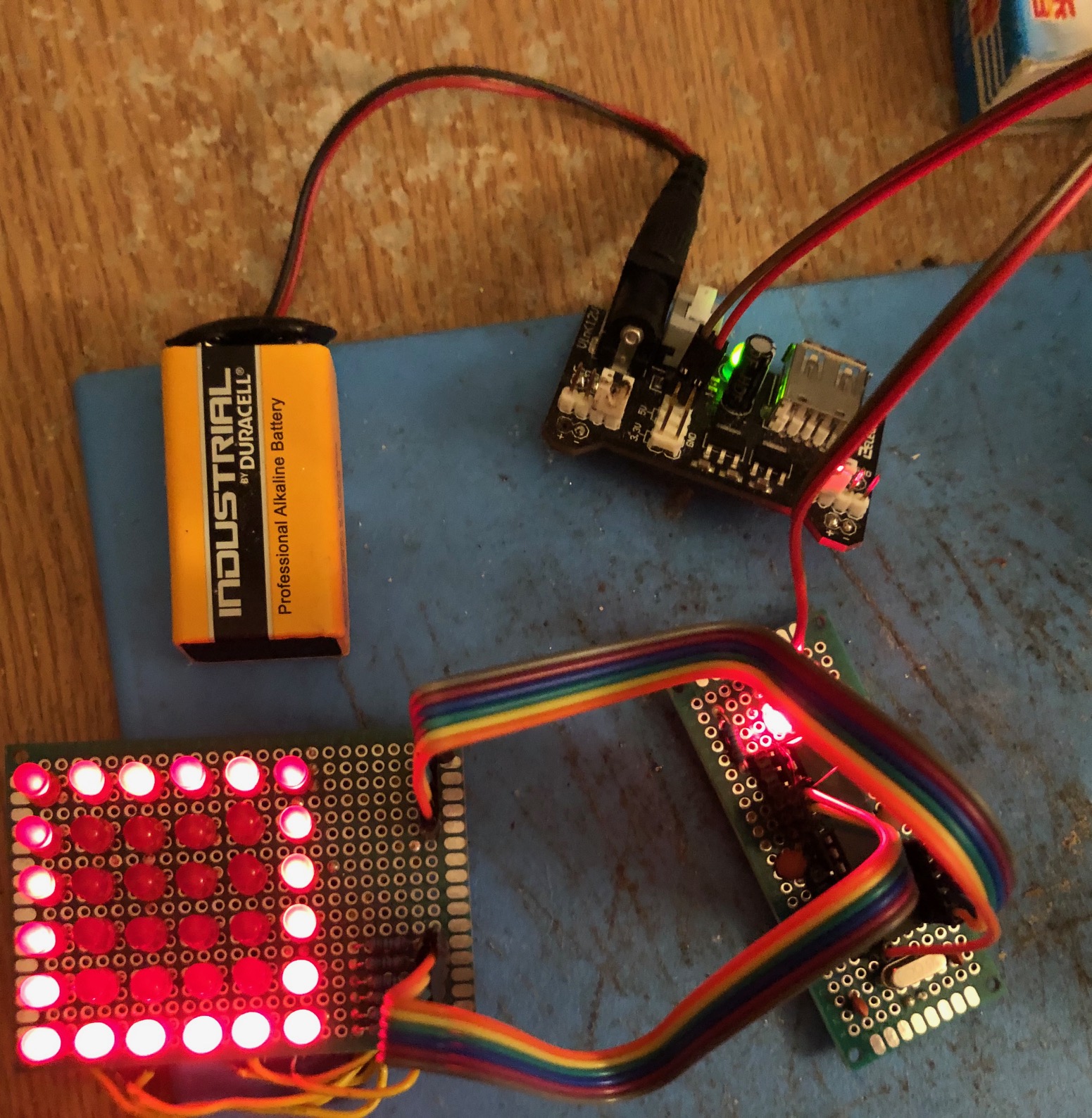
I’ve been thinking for a long while about making a standalone... thing. Something to mark a milestone in my amateur electronics career. I had the idea of making a standalone version of my LED game from previous blogs, complete with a display and a power source. Problem is that it requires the Raspberry Pi to operate, so I was left with the choice of where to go next.

I’d been looking into Arduinos for a while as a way to make a step up to something with a little less help (like, say, an operating system) to get tasks done. The cheapest option with everything I needed seemed to be a cheap Uno clone, and Elegoo make one for about 7 quid. I’d bought their electronics kit before some months ago and apart from a slightly loose connection on some areas of the breadboard I’d been pleased with the product.

Everything arrived and the first thing I did was a breadboard blinky LED, obviously. The issue for me was converting to C after doing so much in Python. I love Python. It's amazing. It's great for idiots like me who treat coding as more like scripting than about devising algorithms yourself. I just glue stuff I find together and pick stuff up along the way - the stereotypical Stack Overflow coder. Probably learn bad habits as well. But the Arduino libraries make things much easier. digitalWrite() may as well be gpio.output() given how similar the syntax is.

Next I converted the LED game code, using the original board I made some months back. Seemed fine, worked first time, converting Python to C isn't as hard as it looks at first. It's also cool having something that self-boots and runs by itself. Obviously you can do that with an RPi, but when you're just doing something as a test or as a one-off you tend not to do that. With an Arduino it just happens, nothing to set up. This makes it much nicer for this kind of application, although obviously having no OS means you have to work a bit harder to do some things.

OK - we're on a roll. What can we do next? Well, what about converting the LED matrix display I made to work with the Uno? Easy peasy. Took me thirty minutes to convert it. That's very cool. Clearly some things will be harder to convert with others, but if you've done something simple on an RPi and thought "bit overkill" then it's relatively simple to convert these tiny apps to Arduino sketches. You'll see that there's a different board connected here to the right of the matrix, which leads to the next topic.

Clearly we have a decent platform here, and something that I can probably use in a standalone format to run lots of simple circuits. The problem is that I don't want to pay 7 quid for a new Uno everytime for the privilege. Thankfully there's a way we can do this kind of thing without having to do that, and that's to make your own cut-down version of an Arduino, using the main ATMEGA328P chip as a base. I'll do a post looking at my adventures into this area soon, but suffice to say I've had mixed results. I can get a chip going and powered in its default state, but I can't change any settings. I also wasted a chip after I soldered it into a circuit that wasn't working properly and that I can't fix. All the legs are bent now so it'll be hard to pull it out.

As ever with this kind of thing my usual stumbling block is having enough ideas for things to do with the kit. It's for that reason that I bought a bunch of sensors and comms boards from AliExpress, and those should arrive soon. I got so much kit...

Honestly, if there’s a sensor or thing you can think of I bought it. And the best thing is that even with ordering from shonky stores on the website I only had one item be incorrect. I ordered some programmable LED strips and I got sent instead... a ladies leather purse!

But I got ultrasound sensors, radio transmitters, an SD card reader, a pressure/altitude/temperature sensor, some odd parts such as inductors and resistors, some nice chips like audio amplifiers, some level shifters for combined 5V and 3.3V work, and so much more. Now all I need is an imagination, which is harder than it sounds.

❌
❌