via HACKADAY: Learning Morse Code with a DIY Trainer
25 June 2024 at 20:37
Morse code, often referred to as continuous wave (CW) in radio circles, has been gradually...

After reading a Radcom article about a 10MHz locked ADF4351 Arduino controlled signal generator thanks to Alain Fort F1CJN described here, it seemed the perfect module for testing equipment locally as I didn’t have anything like this.
Once the pieces arrived from China it worked perfectly with a 10MHz GPSDO input using the instructions from Alain’s page above and the black ADF4351 board after disconnecting the on-board 25MHz clock.
![]()
When connected, the above worked fine and did okay on the desktop it wasn’t suitable for moving about or with the jumper cables for long term storage/use. A box was ordered large enough to place all of the bits in and to allow SMA & DC inputs as well as another shield that didn’t have the headers I’d put on the above one.
The Arduino LCD/Button shield works well but doesn’t lend itself at all well to being installed in a box. The LCD brightness adjustment trimmer is too big, there are some header pins sticking up to the LCD level and the buttons are too far recessed for access through a box. Some discussion on the ukmicrowaves mailing list gave pointers for getting around these problems.
Firstly the buttons were all removed and the trimmer was moved to the other side of the PCB.
![]() I wasn’t sure of the size of buttons to replace the originals with to allow them to be pressed when mounted in the case so I had also ordered a mixed pack on eBay to allow picking the appropriate size. I also ordered some white caps for the tops which would eventually be glued on. I eventually settled on the combination lush with the LCD.
I wasn’t sure of the size of buttons to replace the originals with to allow them to be pressed when mounted in the case so I had also ordered a mixed pack on eBay to allow picking the appropriate size. I also ordered some white caps for the tops which would eventually be glued on. I eventually settled on the combination lush with the LCD.
![]()
Now came the part I wasn’t looking forward to, drilling and cutting the case. The LCD shape along with the four mounting holes was drawn out based on measurements from the board and cut. I don’t have any nice tools for the LCD rectangle cut so cut two sides with with a hand hobby saw and others with a rotary tool to compare the finish as wasn’t sure of the best approach. The rotary tool was fast but gave a terrible finish, the hobby saw plus sanding gave by far the better result.
The more tricky bit was the button measurements and I couldn’t find a PCB diagram for the board. Putting some fabric tape on the inside of the case and ink on the top of some temporary placed buttons I pushed the LCD in to it’s fitting which after a couple of goes left an imprint on the inside.
![]()
This allowed me to drill an initial hole from the inside before turning over to drill an appropriate sized hole from the other side.
![]()
Once I had validated the holes were lined up, they were expanded to fit the white caps using a drill and a deburring tool. I then checked the button lengths for the best match, soldered the buttons to the board and glued the white button caps to them.
Three holes were drilled in the side for two SMA and a DC input and some stickers added to make it look better by hiding the messy top cut made by my bad effort with the rotary tool…
![]()
The inside has the LCD shield and Arduino attached to the lid using machine screws and some spacers to hold things in place. The Arduino needed it’s DC socket removed to fit flush with the LCD shield. Wires were soldered directly in to the Arduino for the output to the resistor divider and DC input.
![]()
In the picture above the DC input is going to the Arduino DC input. However the regulator in the cheap Arduino Uno copy I’d obtained from eBay turned out not to work with a 12v input in the same way as the genuine Uno I tested with had. To sort this I skipped the regulator by putting a small buck converter in the case to let it regulate the voltage to 5v and connected it directly to the 5v on the Arduino. As well as solving the problem, the converter gives better a 6-20v input range potentially at the expense of the converter introducing noise.
![]()
The harmonics produced are strong enough to provide an accurate marker at 10GHz and likely beyond.
![]()


![]()

There is a total of 10 different bars and here are the two which are used in the upcoming version of the Multi face GPS Clock.

This excludes some fancier bars that require more or less continuous updates of character sets during progression of the bar.
The code and images of the other eight bars can be found on Github.
![]()
A brief press on the rotary encoder will enter the setup menu with these options:
< 0 Clock subset >, < 1 Backlight >, < 2 Date format >, < 3 Time zone >, < 4 Local language >, <5 Secondary menu>.
Submenus will lead the user to :
Chosen values will be stored in EEPROM so next time the clock is started it will start with the values used in the previous session.
A long press will reset the clock.
The code can be found on Github.
![]()

This is screen number 39 for this clock, all of them selectable by rotating a rotary encoder. The project, with Arduino Mega hardware and software is documented on Github, where the current release is v.1.6.0 (2023-04-14).
The display also shows the full name for the element corresponding to the second, as shown above for element 3 which is Lithium. It is located in group (column) 1 and period (row) 2.
![]()


![]()
The multi-face Arduino GPS clock is inspired by the Clock Kit from QRPLabs. It is an open source project on GitHub, and it now has support for many more languages in the newly released versjon 1.4.0. As a language nerd myself, I love fiddling with multiple languages and character sets.
The local language option is for display of day name in case local time is shown. The default is English for local time. No matter the choice for local time, English is always used for UTC day name. Here are examples:
French:


![]()


![]()
Main links for documentation
![]()
The Norwegian Ham meeting 2022 will take place 11-13 March near Oslo Airport Gardermoen. Norwegian and some Swedish radio amateurs will meet and the program is here (Norwegian). It will be nice finally to meet again!
I will give a presentation on Saturday morning: "An easy-to-build GPS clock for the shack".
![]()
![]()
The GPSClock from last month has now been updated and software version 1.10 1.1.0 is available on Github. The main upgrade is the possibility to use a rotary encoder for selecting display screen or clock face.
In addition a new screen showing Easter for the next three years, according to both the Gregorian (Western) and Julian (Eastern) calendars, has been added as number 22. The dates are shown in the Gregorian calendar:


![]()
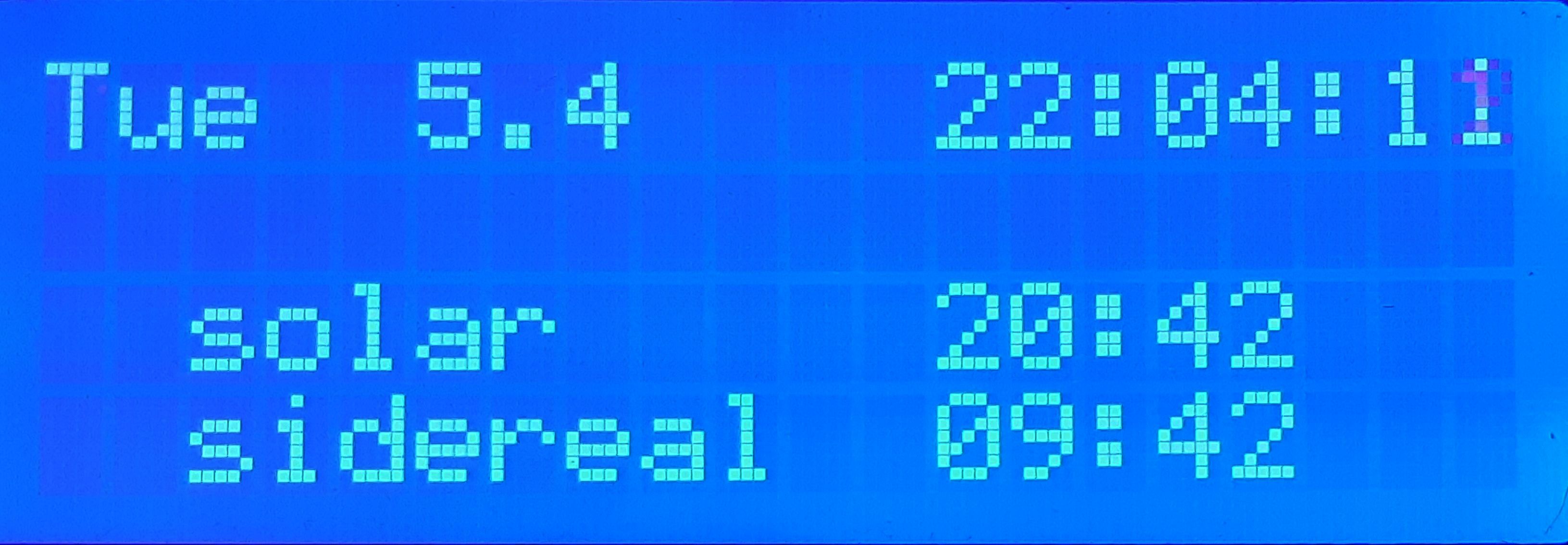
Version 1 of my Multi Face GPS Clock is here, as open source software for the Arduino Mega. It has some 22 19 different display screens showing time, location, solar and lunar positions and rise/set times. It shows UTC time as received from the GPS satellites and local time where it automatically adjust for summer time. The initial screen, no. 0, is this:

The display changes by pushing the right-hand pushbutton on the top, increasing the screen number by one. Similarly the number can be decreased by pushing the left-hand push-button. The potentiometer on the right side adjust the backlight. The clock is built on the same hardware as used for the K3NG Arduino CW keyer.
The date and time formats may be changed, and with US settings it looks like this:


![]()

Finally, over the last few weeks I managed to adapt lunarCycle.c to Arduino and get it to work as shown in the display here. My ambition is now eventually to publish this project on GitHub as I’ve had several requests for it.
The display here shows local time and date, moon phase on line 2, present moon elevation and moon azimuth on line 3, and the next rise time of the moon and at which position on the final line. Follow label ‘Arduino clock’ below for more posts about this clock.
![]()
I have some spare ATmega328 chips that are not programed and can be used in some projects specially now the prices Arduino boards got some inflation.
In order to upload the program to the IC's you will need to burn first the bootloader, at least so that later you then upload via de Arduino IDE.
Schematic and instruction are from here: https://docs.arduino.cc/built-in-examples/arduino-isp/ArduinoISP
End result:

Another view:

For uploading: select the Arduino programmer USB port and then the programmer type "Arduino as ISP", in the end just "burn bootloader".

After bootloader burn:

Have a great day!
![]()
There are times when you wonder if your receiver and antenna are really working as they should. The band is dead, or empty, it’s the middle of the day, the D-Layer is sponging up every radio frequency excitation. Perhaps you can hear a few signals, but they are fleeting — and you need a steady and predictable signal source for a proper test. An RF signal generator will give you a steady carrier, but there are times when you’d prefer to have a true CW beacon to tune onto. This simple, general purpose multiband CW beacon can be run up on the frequency (or frequencies) of your choice, is powered on a 9V transistor radio battery, and can moved to attenuate to the desired signal level, for radio receiver system testing purposes.
This beacon transmits a hard-coded message in morse code on any frequency supported by the si5351 (10kHz to 160MHz). The code targets an Arduino Nano, Uno or bare ATMega328P and an si5351 breakout board. No display is necessary. You can add one, and controls, if you like. The code includes a simple CW keyer for manual sending (not used, but left in place for this application).
Any number of frequencies in the HF and VHF range can be specified by adding them to an array of transmit frequencies. The beacon iterates over the array and transmits the message on each frequency in sequence. The beacon’s CW speed is configurable. Sidetone is available as a 5v square wave on the D7 output. There is no support for switched low pass filters but this would be easy to add.
The Github repository is here.
![]()
There’s a reason why most homebrew transceiver kits and scratch-built projects are monoband and single mode — theres a chance you’ll finish it, or at least, get it working for a while. Building a multiband HF transceiver is a big job, as any homebrewer who has attempted it will tell you. It may take years.
My build of Eamon EI9GQ’s transceiver is no exception. It was started in 2018, the first rush of enthusiasm resulting in a working superhet receiver on 160 to 40m, and boxed up in a custom solid aluminum case. This video shows it off circa 2018.
With a heap of work ahead, and a list of unresolved minor problems, other projects took priority, and the rig ended up spending the next four years in a carton (with all my notes, schematics, assembly and PCB sketches, and unused components). Until recently.
It’s my normal practive to include kicad schematics, but in this case the EI9GQ designs are copyright RSGB. So go and buy Eamon’s book from the RSGB Bookshop, or on Amazon, you won’t be disappointed.
E-mail discussions with another keen maker (Neville ZL2BNE) about his build of this transceiver gradually tickled my interest to resume. Nev was making good progress, had his rig transceiving, and was working QRP DX. I dug mine out of its carton and fired it up — it had all the appeal and problems that I remembered from 2018. I resolved to kick it along the road for a bit, to see how much interest I could reconstitute. Upon resuming, a number of issues needed addressing, some easy, some repetitive, some more difficult but not impossible. Here are those that I can remember…
Firstly, the 9MHz IF amplifier oscillated with the manual AGC turned up, and was generally unstable. To fix this, I put a 5k5 resistor in parallel with the drain tuned circuit — a well known technique for taming high gain stages. I figured that of the three identical 15 to 20dB gain stages, it made sense to damp down the gain of the first stage. This did the trick, and all three stages exhibited a nice resonance peak using the trimcaps, and overall stability.
The next thing was to calibrate the si5351, a simple job I’d never bothered to do, resulting in the display showing odd and fractional frequencies for the property resolved SSB stations in the 2018 video. If you want to know how this is done, go to your si5351 library’s README file, it is quite easy to do, and once done, lasts for years, or for ever.
Next problem was the LCD backlight. The large font 20×4 LCD I had chosen for this rig was a bit of a novelty back in 2018. I liked that it’s huge characters could be read from half a room away. I used to joke with myself that I’d still be using this rig in my 90s, when all the compact rigs with fiddly little OLED displays were beyond my failing eyesight. And the four lines of 20 characters gave me extra display space for luxuries like a UTC clock and metering. But that big display had an equally oversized backlight which could light up a darkened room, but drew more than half an amp. Although this rig was intended for the shack bench, I was not used to my receivers pulling over an amp.
I decided to multiplex the LED array with a simple PWM LED dimmer, which uses one half of a 4093 quad gate as a variable duty cycle oscillator running at around 70kHz, driving an IRF540 FET switch. This worked a treat and the dim potentiometer was mounted right on the front panel. It controls the backlight from off to 90% on, when it drawn around 500mA.
The next mini-project was an AM detector. I was not interested in full AM transceive capability– I have other homebrew projects for operating VK legal limit AM — but I did want to be able to enjoy decent AM reception using the high quality 6kHz filter in this receiver’s set of three KVG crystal filters. I chose an infinite impedance AM detector, successfully used in a prior AM receiver project.
This mod necessitated making a PCB to overlay the existing product detector and audio preamp, with a plug-in board containing the AM detector, it’s own preamp, a miniature relay to steer the incoming IF signal to either detector, and a shared 4046 quad bilateral analogue switch which selects the product or AM detector’ s output, and additionally does receiver muting and Sidetone routing when in CW transmit mode. This assembly worked well. One hickup — I originally left the BFO powered up in AM mode — and even though there was no direct BFO coupling anywhere, there was more than enough stray coupling to resolve sideband. This was fixed by switching the BFO board’s DC power off in AM mode.
The next task involved coming up with a mechanism to select one of the three KVG (ex TelRad) filters. These high quality 9MHz crystal filters were common on eBay a few years back, and are a feature of this receiver. These filters came in a set of three. In a slight departure from superhet convention, a separate filter is used for USB and LSB, with a 6kHz AM filter in the middle. The BFO runs permanently on 9Mhz. I wanted to have filter selection under software control, so that the correct sideband filter would be selected for the current band. One of the front panel pushbuttons was used for a mode control — pushing it cycles thru the sidebands and an AM setting. A small daughter board was added to the filter assembly containing a PCF8574 demux IC on the I2C bus. A few additional lines of code implemented a simple control function.
The 2018 receiver’s front end board included space fo r an RF amp block, with a pair of miniature relays to bypass it. The original PCB was layed out for a MMIC which probably would have worked fine but in the end I built up one of EI9GQs broadband RF gain blocks using a parallel pair of MPSH10 transistors for around 20dB of gain. The EI9GQ amp was built on an overlay board sized for the available space.
A few minor additions followed. A 41MHz Low Pass Filter was added on the VFO buffer input. On the highest band (28MHz) the VFO is 9MHz higher, on 37MHz. This low pass filter cleans up any VFO harmonics, probably low anyway, but a safety precaution.
The diplexor was added, a balanced tee arrangement, with series and parallel 9MHz tuned circuits arranged to pass through 9MHz energy, but sink all other frequencies into 50 ohm resistors. This ensures proper termination of the receiver mixer and keeps unwanted mixing products, particularly at the image frequency, out of the first IF amplifier.
One of the nore repetitive jobs (which just has to be done!) is making and tuning up the remaining Band Pass Filter modules. Three mire were built, for 17, 15 and 10m, using the EI9GQ design. This gave eight bands, 160, 80, 40, 30, 20, 17, 15 and 10m. My approach to the last three boards was mostly as I’d used in 2018, other than improving the use of right angle 0.1″ header pins inserted through a row of holes drilled through the PCB for mechanical strength.
Next job was a small board mounted on the rear panel next to the two SO239 sockets. This board has the transmit-receive relay, and a second relay that switches between two SO239 for an Antenna A/B switch. Three 7812 regulators supply the three supply rails, 12v always on, 12v receive, 12v transmit. All three unregulated DC supplies are available on headers as well, to avoid heavy current being drawn thru these regulators, such as the transmitter PA and the LCD backlight.
The rear panel has two antenna sockets (for A and B antennas, switched from the front panel), a panel XT60 socket for DC 12V, and a set of 3.5mm and RCA sockets for connections (external muting, paddle, external speaker, and an auxiliary RCA, as yet unassigned). These 3.5mm switched stereo sockets are very useful pieces but unfortunately are not long enough to go through a 3mm aluminum panel. The best solution is to mill out a recess larger than the socket, but that requires a milling machine that I don’t have. So the workaround was to cut a rectangular hole in the 3mm rear panel, and bolt on a 1.2mm aluminum plate to hold the sockets. Its easy to paint and label this small piece.
To turn the EI9GQ receiver into a transceiver I needed a microphone amplifier, balanced modulator, transmit mixer, T/R switching, a PA stage and LPF set. Back in 2018 I built Eamon’s LM324-based microphone amplifier (a design out of EMRFD) and another hand made diode balanced modulator. All of these mixers use 1N5711 Shottky diodes individually matched to within a millivolt on the diode test setting on my digital multimeter. The transmit mixer is another hand made diode ring mixer, this time an unconventional triple balanced mixer.
The PA chain after the transmit mixer will be MPSH10 x 2, 2N5109 and a pair of RD16HHF1s for about 10 watts 160 to 10 meters. The LPFs will be by Eamon, derived from the original W3NQN designs, each filter on its own plug-in board, relay-switched at either end, filter selection via another PCF8574 on the I2C bus. There will be six LPFs (for 160, 80, 40 and 30, 20 and 17, 15 and 10 meters).
If you’ve made it this far, thanks for reading, feel free to leave a comment, and stand by for the third and final post on this transceiver project, which will address completing and commissioning the SSB and CW transmitter stages.
![]()
Weak Signal Propagation Reporter is a global radio propagation monitoring and reporting network comprised of thousands of low power beacons operating on the amateur radio bands. WSPR beacons can be detected from the lowest of Medium Wave frequencies (137kHz) all the way through the HF spectrum (all the bands from 160m to 10m are popular) to the VHF bands, 50 and 144MHz. WSPR receivers decode the tiny beacon packets and upload them to a central database, at WSPRNet.org, where anyone can literally ‘see’ the propagation paths that are currently open.
Equally, you can go back and revisit the radio frequency propagation conditions during any previous time window. Running a WSPR beacon from your home allows you to ‘watch’ the propagation paths open, peak, and close each day under the influences of solar radiation, sunspots, and other ionospheric conditions. Arduinos and a few common accessory boards that can be had for tens of dollars make a beacon accessible to just about any experimenter (with an amateur radio license).
I’m late to the WSPR party. I’ve wanted to try a beacon project for a few years. A while back, I took a copy of the ZachTeck script and experimented with it and a Ublox GPS, but after getting the NMEA strings decoded from the GPS unit at roughly one second intervals, the rest of my code was over-engineered and bloated, and did not fit into the small memory constraints of the Arduino Nano. I put is aside.
Recently, I did a much needed upgrade to my Arduino IDE and libraries. The thought occurred to me that improvements to both IDE and libraries may give me a fighting chance of getting that old WSPR script fitting. When I opened it up, and started to work through it, I saw some obvious ways of reducing memory usage. I had too many String objects (memory-hungry). And my code was writrten to parse each NMEA message string and tokenise it. This allowed me to get to discrete data fields a long way down the messages, like the number of detected satellites. In a simple WSPR beacon, all you really need is the UTC timestamp at the very start of a number of the NMEA messages. I ditched the superfluous stuff and got it uploading, and more to the point, not hanging!
WSPR is brilliant for teaching you about rare and exotic places that you feel compelled to Google when they turn up on your map in the morning, places like Orlygshafnarvegur (TF4AH, Iceland) or Fuerteventura (EA8BFK on the Canary Islands).
The database of historical propagation across the HF spectrum is widely used by amateur researchers to learn about propagation and has some more serious applications as well. Experimenters have used the data to support ideas or research questions about how symmetrical propagation is at opposite sides of the globe in the same period, and to test antennas. More seriously, a theory was proposed that impressions in the WSPR dataset may indicate the path of the lost flight, Malaysian Airlines flight MH370.
The script is here: https://github.com/prt459/WSPR_GPS_Beacon
The schematic is so simple it really doesn’t need a kicad. The Ublox 6M GPS connects to Arduino D2 and D3 for serial data transfer. It also needs GND and +5V. The si5351 breakout board uses I2C and so goes to Arduino A4 (SDA) and A5 (SCK). Connect the si5351’s CLK0 to whatever low power HF amp you like. Mine is from Experimental Methods in RF Design (EMRFD), Fig 12.32, but I could have chosen any number of similar two-transistor stages.
WSPR works on truly tiny power levels. If you connect the bare si5351 clock output to an antenna, you will get decodes! (You should add a Low Pass Filter if this is anything more than a quick test). So use a single 2N3904, or anything with gain, up to a full 5 watt QRP PA with an IRF510 or Mitsubishi RF FET, which is a ‘big gun’ in the WSPR world. Mine uses a 2N3904 and 2N4427 in common emitter feedback configuration, delivering around 10 volts peak to peak into 50 ohms, followed by a W3NQN Low Pass Filter for the band of interest.
Thanks to Harry from ZachTek for making his code open source. And to Jason Milldrum NT7s for his si5351 and JTEncode libraries.
After publication of this project in the RSGBs SPRAT #192 Autumn 2022 a number of builders commented below the post or contacted me with build reports and questions.
First, the 12v DC series decoupling resistor was not labeled in the published schematic, it can be anything between 47 and 100 ohms (see corrected scheatic below).

Secondly, Ian McCrum did an LTSpice model of the PA which revealed that I omitted a resistor from the original design in EMRFD (in parallel with the 100n coupling capacitor between the stages) which forms part of the biasing of the PA transistor. If omitted, the PA works, but with reduced power. Adding the resistor increases the RF power output to around 0.5W, although this will vary depending on drive level, the PA transistor, and the DC supply voltage. Thanks Ian for taking the time to LTSpice this QRP PA.
Steve K8SDK got more power out of his PA by increasing the si5351 drive level from 2MA (my value) to 4, 6 or 8MA. There is a general understanding and some analyses that report the si5351 clock phase noise gets dirtier as you go up in drive level, and for this reason I left it at 2MA. But with sub 1 watt power levels and a LPF on the output I don’t think it would make any practical difference.
On the question of WSPR beacon power, I don’t think 0.5W is preferable to 0.2W under curent band conditions. With 0.2W the decodes at DX WSPR receivers get marginal and the spread of the band opening can be seen as the grey line moves across the globe. Higher beacon powers can result in saturation which looks like a more rapid ‘lighting-up’ of the remote receivers on the map, and the subtleties of propagation can be lost. This is another way of saying that you should really use a minimum power necessary to get decodes at the far end. However my preference for low power is a personal preference, and some may need slightly higher power to overcome antenna losses.
Several people reporting having to use the set_correction() call with the second parameter (around line 320). I added a comment note immediately above the call in question:
// NOTE: There was a library change to the signature of this method. If you get a compiler error, try this:
// si5351.set_correction(19100, SI5351_PLL_INPUT_XO);
I did it this way to allow for compatibility with subsequent versions of the NT7S si5351 library. But a few people got the compile error and did not trace it back to the offending source line, or perhaps read the comment. I should have just made this change in the repo code to make it foolproof for all comers.
Neil G0ORG emailed with a question about si5351 calibration, his calibration attempt resulted in a value of 149850 for the call to set_correction(). I personally have not seen a calibration offset that large, however, the tiny crystals on the Adafuit and clone breakout boards must vary considerably. Neil reported that this offset pulled his si5351 outside the WSPR passband — we are not sure what went wrong with the usual calibration process for this to happen, bit Neil got his beacon back on the spot by experimentally reducing this large offset value.
Stephen G3ZNG had problems compiling the sketch, and after a bit of investigation discovered he had a previously installed JTEncode library. Upgrading the library fixed the problems and Stephen reported his beacon was working.
Chris G4BMW had the same problem. When he installed JTEncode v1.3.1 and Si5352 v2.1.4 it worked. Chris then discovered that GPS units do not always work inside, and had to move his unit next to a window to give the GPS receiver a sniff of the overhead statellite’s signals.
John G8CHP emailed me a photo of his completed WSPR beacon in a sandwich box. John reports spots in western Canada from his QTH on the east coast of the UK. John used a QRP Labs QLG1 GPS unit, mainly because it was on hand, and a 2N3866 for the PA.
Jonathan G5LUX got his beacon working on a breadboard, and it worked first time.
Aaron K5ATG emailed to discuss his build options, saying that most commercial WSPR beacon products are reasonably pricey for what they are, and my design is made from just a handful of commonly available components, most of which he already had.
Nigel, G4ZA emailed me to say that he had also come up with his own homebrew WSPR beacon, and that Harry’s code (Zachtek) saved him a ton of work too.
Steve K8SDK used three FETs (presumably in the conventional Class E PA configuration as used in many QRP CW PAs) (see comments below post).
And finally, Dave AA7EE has done a superlative job of building his own WSPR beacon using my script, and of course, his blog write-up is amusing, informative and a celebration of the finest amateur radio homebrew spirit. Dave set up his beacon on 10m but had si5351 stability issues which he describes in detail. He solved the drift problems with patience and experimentation, eventually settling on 20m. His post shows remarkable QRPp WSPR results. Thanks Dave for the acknowledgments peppered throughout your post. (See also Dave’s comments below).
A number of builders commented below the post, please read for further discussion. As well, I did receive other emails so if I have missed you please leave a comment below.

Working beacon by G5LUX

![]()