This document explains how to communicate with FT8 on UV-K5.
1.About using FT8 in UV-K5
UV-K5 can receive SSB (DSB). However, SSB transmission is not possible.
If you set the UV-K5 to SSB mode and speak while holding the PTT, you will probably be able to receive reception from other SSB radios.
But that's not SSB mode. When transmitting in FM mode, it is received by the SSB radio.
The frequency needs to be changed slightly on the receiving end. (depends on FM Devaition)
Therefore, the FT8 protocol was implemented in a digital manner rather than in voice mode. This is similar to FT8 and WSPR beacon implementation using DDS chips such as SI5351.
Therefore, the WSJT-X program had to be modified and you must reinstall the attached WSJT-X to operate FT8 mode using UV-K5.
2.WSJT-X Install and setup
Download and install the program from the link below.
Introduction to UV-K5 HF 0.5 (Fullband receive version)
This is an introduction to UV-K5 HF full-band reception firmware 0.4HF using SI4732-A10.
This version is released separately from the existing UV-K5 CEC firmware version. because space is needed to store a large PATCH file to use SI4732-A10's SSB.
This article only describes the features newly added in Version 0.5.
- When you select a band from the Band Plan menu, the mode appropriate for that band is automatically set.
- Unused and unnecessary menus have been removed. (Main VFO Mode, not HF Receive mode) : U.INFO, Key.LCK (If you press the F key for a long time in main vfo mode, Lock will be activated or deactivated, so it has been removed from the menu)
I created an externally mountable DSP-Board to process digital signals from UV-K5.
DSP-Board was named C-Board. C-Board is divided into versions ranging from the simplest version to one that can be equipped with GPS.
Version history of this document
- If the C-Board does not operate due to insufficient current, UV-K5 modification
- gps schematic update
0.About C-Board
To apply the DSP-Board to UV-K5, we first implemented a high-speed communication protocol. The videos below use the protocol.
0.1 RP2040 board I used #1
This is the cheapest board. It's usually around $1.4 and sometimes sells for less than that during discounts.
Below is my order details. About a month ago, the product was on sale, so I bought 3 for $1.18
The components are mounted on both sides of the PCB, so they are a bit difficult to attach.
This is also the RP2040 board I use.
Since there are no components on one side of the PCB, the C-Board can be made a little thinner.
The C-Board created in this article uses this board. It can be made in the smallest size as shown in the picture below.
1.Basic Version
It performs all DSP-related functions, but you cannot hear sound.
(Recommended)
The UV-K5's audio signal comes out at close to 8Volts when the volume is maximized. The ADC input range of RP2040 used in Raspberry pi PICO is 0~3.3Volt.
You can use it by reducing the volume appropriately.
I don't know if the ADC bypasses excess current, but no major problems occurred even when the volume was set to maximum.
(Not recommended, but the circuit I use)
2.monitoring version
A version equipped with additional speakers for monitoring and a microphone for simple communication.
Note 1: If you want to hear loudly, the bigger the speaker, the better. I got satisfactory results with speakers about 1cm wide.
Note 2 : The resistor connected to the speaker must be capable of transmitting high current. I use five100 ohm resistors connected in parallel as shown below.
3.GPS Version
3.1 When using low-power GPS (no modification required for UV-K5)
I used the GP02-Kit, and this product can use the 3.3V of the C-Board.
The widths of the GP-02 Kit GPS and RP-2040 Board are the same.
When GPS was first installed on UV-K5 a few months ago, it was possible to fold the GPS.
However, as a result of testing, there is no major problem even if installed as shown below.
When updating the firmware of the C-Board, you must press the Boot switch mounted on the RP2040 board below. It is difficult to press the button when equipped with GPS.
It is also a good idea to extend and install the SW. It depends on your idea.
For reference, I simply placed paper between the switch and the GPS.
When you press the GPS button with force from above, the Boot switch is pressed.
3.2 How to use a separate power source (UV-K5 modification required)
Even if 3.3Volt is supported, it is difficult to use simultaneously due to excessive power consumption of GPS.
Therefore, a separate power supply unit must be added
Note 1 : Most GPS are equipped with a regulator that converts 5.0 Volt to 3.3 Volt.
All four types of GPS I have are equipped the same way.
When replacing the 5.0 -> 3.3 converter mounted on the GPS with a general 3.3 regulator, the lm1117 5.0 part of the above circuit can be omitted. (general 3.3 regulator support 8.4 volt input)
In the picture below, the component in the square box is a 5 Volt To 3.3Volt regulator.
I took 8.4Volt from the point indicated by the arrow in the picture below.
4.Tip
4.1 You can make it by cutting the headset or programming cable.
If you purchase the cable below, you can get two plug parts. However, most plugs have only three wires connected. You have to cut the plug with a knife and solder all the wires together. It's not an easy task.
A version made with the same plug as above.
4.2 use 3.5mm and 2.5mm plug
I have recently purchased and made a plug like the one below.
To ensure the correct location and direction of the plug, insert the plug into the radio and mark its location.
Basic version
Monitorring versoin
I cut the plastic and made it into a case. If you or someone around you uses a 3D printer, you can make a cooler case.
Installed
5. Use of UV-K5 and C-Board
5.1firmware upload
1.While holding down the Boot button, connect the USB to the computer.
2.A removable disk called RPI-RP2 will appear on your computer.
3.Copy the firmware file and paste it into the RPI-RP2 disk.
The firmware is currently under development and will be distributed together with the release of UV-K5 firmware CEC versin 0.4.
If you need firmware even before Version 0.4 is released, we will send it to you by email.
(No additional equipment is required to upload firmware to the C-Board.)
SSB Receive TEST
Receive FT8 and Decode using UV-K5 with C-Board (Standalone )
5.2 When C-Board does not work
- Some UV-K5 devices have current limitations, so the C-Board may not operate.
- In some cases, the C-Board works, but only when entering FT-8 mode.
This also means that the current supplied to the C-Board is insufficient. When operating in FT8 mode, more current is required due to overclocking.
- The C-Board operates normally, but when connected to GPS, it does not work.
I tested a total of 8 UV-K5s and had problems with 2 of them. This issue was reported by a beta tester a month ago.
Resolution
1. Connect a resistor of 2 to 5 ohms to part A in the picture below.
(I connected 3 ohms (3 10 ohm parallel))
Most problems will probably be solved by simply adding a resistor to point A.
2.If the problem is not resolved yet, install a 10 ohm resistor at point B. (This part is mostly unnecessary)
In my case, one UV-K5 had to be modified at both points A and B to use the C-Board with GPS.
Example (My Case)
I removed the original 47 ohm resistor at point A for testing, but you don't need to. (2~5 ohm resistors are connected in parallel, so the 47 ohm resistor will be ignored)
Introducing UV-K5 Version 0.3C (Added WSPR , APRS TX with PC )
Version 0.3C includes tasks associated with computers. You can use the same cable you used to update the firmware. If you just want to receive APRS you will need some modifications. This modification can also be used for FT8 communication that will be supported in the future.
0. About UV-K5 v0.3C
-DIG.M (Digital Mode) menu has been added. When Digital Mode is ON, the External CW Key does not work. When using the CW Key, turn Digital Mode OFF. If the Digital Mode is changed (ON->OFF or OFF -> ON), be sure to turn the radio off and then turn it back on.
-Stand alone WSPR function has been added. Before going outside, use UV5DigManager to input WSPR information into UV-K5.
-A function to send APRS messages by connecting to a computer has been added. You can easily receive data by simply modifying the programming cable (the cable used when updating the firmware).
-The cable used in APRS is also used for connection with WSJT-X, which is scheduled to have additional features in 0.3X
-AMFIX applied when receiving from Spectrum & Waterfall (Todo in 0.3B)
-Fixed issue with GPS coordinates with more than 4 decimal places in APRS (Todo in 0.3B)
- STATUS (top of screen) ICON rearrangement
- Fixed issue where the Monitor function is activated under certain conditions when Spectrum & Waterfall is closed. ( Commented by Sean, N7SIX)
- APRS, SSTV SideTone volume (Added in Version 0.3) changed ( -> 100)
- CWFM (F2A) SideTone volume changed ( -> 100)
- Remove SSB Filter menu, The SSB Filter function has not been deleted. When SSB mode is selected, 2K+ (BandWidth 3~4Khz with Hacked function) operates automatically.
- Remove Live.Seek Menu, The Live Seek function has not been deleted. It operates fixed to Live Seek.2. (Signal detection and simple spectrum display when moving frequency with direction keys) The Live.Seek feature may be deleted if a replacement feature is added to Spectrum & Waterfall.
1. Digital Mode ON
To save WSPR data on UV-5K or transmit APRS using a PC, Digital Mode must be turned on.
Caution: When Digital Mode is ON, External CW Paddle or External CW Straight Key can no longer be used. When using the External CW Paddle, be sure to turn off Digital Mode.
If the Digital Mode settings are changed, turn off UV-K5 and turn it on again. (Reboot)
'DIG.M' in the menu and change it to ON.
After the value is changed, turn off and turn on UV-K5.
(If the DIG.M value has been changed, be sure to reboot. UART operates at high speed)
If 'DIG+' is displayed on the screen, it is ready to receive data from the PC.
You do not need to do anything on UV-K5 to receive WSPR data from a PC or transmit APRS data using a PC. Please keep this screen as is.
2.Saving WSPR data to UV-K5
Before you go outside, you must save the data required for WSPR transmission in UV-K5.
If you go to SOTA, the coordinates of the mountain in question are stored in UV-K5 in advance.
2.1Connect UV-K5
To save WSPR data on UV-K5, connect the data cable. (You can use the same cable used for firmware update)
2.2 Run UV-K5 DigiManager
Select the Serial Port where the data cable is connected and click the Connect button.
2.3 Entering WSPR data
Power does not adjust the RF output of UV-K5. This is simply data transmitted along with WSPR transmission.
For RF output, please select one of H, M, and L on UV-K5.
2.4 Transferring data to UV-K5
After entering all data, click the Transfer button.
If WSPR data has been transmitted, it is displayed on the UV-K5 screen as shown below.
You can additionally save the second and third data by changing the number at the beginning of the WSPR item.
3. Send WSPR
3.1 Send
To transmit WSPR, only one UV-K5 is required.
Select T.WSPR from the menu.
Press the ‘Menu’ button once more.
The WSPR frequency and WSPR data stored in UV-K5 are displayed on the screen.
At even minute 00 seconds, press one of the buttons 1, 2, or 3 for more than 1 second.
Transmission takes approximately 120 seconds.
3.2 pskreporter
The WSPR you sent can be checked through pskreporter.
The UV-K5's frequency is quite stable. It operates much more stably than the SI5351 module, I experimented with VHF WSPR on UV-K5 and received everything successfully.
Additionally, I enabled WSPR to be transmitted in the 50Mhz and 28Mhz bands.
To use 50Mhz and 28Mhz, you must install an LPF or BPF filter. The spur signal is generated louder than the main signal.
The WSPR frequency is automatically selected to be close to your VFO frequency. (Only 2M, 6M, and 10M are available)
To use the 6m band, enter any 6m band frequency and run WSPR.
4. APRS TX using PC
4.0 APRS on UV-K5
If you are trying APRS for the first time on UV-K5, you must save the APRS transmission frequency in the channel in advance.
Tune the regular VFO to the APRS frequency appropriate for your country or region.
Then go to the ChSave menu and move to the very end.
Then, the APRS MSG or APRS GPS item will automatically appear.
You can save it there.
Save both APRS MSG and APRS GPS.
- This is to transmit APRS at any time while your radio is in operation.
4.1 Data Cable Mod
To transmit APRS using a PC, you do not need to modify the data cable.
However, simple modifications are required to receive APRS data. You must connect the frontmost signal (audio) to the 2.5mm plug.
In my case, I cut the DATA cable with a knife to connect the wire to the very front of the 2.5mm plug.
Caution: Be careful when soldering GND (the rearmost part of the 2.5mm plug). The plug may melt. It is recommended to connect GND in the middle of the cable.
Insert a resistor (5k~20k) between the wires connected to the frontmost part of the 2.5mm Plug
Just connect to the Line-In or Mic-In of your computer. You can also use an Audio Sound Card.
This cable will also be used in the future when using FT8.
4.2 Run UV-K5 DigiManager
Select Comport and Click to 'Port Optn'
Select Type (STATUS or Message)
After entering all items, click the Transfer button.
4.3 Receive APRS
I don't know much about APRS.
This time, while developing the APRS function, I ran the programs provided by testers.
Rather than using the information below, please contact APRS experts near you.
I tested it with Dire Wolf. Receiving is also possible.
Transmission is all handled by the UV-K5, so all you have to do is set up Direwolf's Audio IN.
Expert Mode : file : CEC____C.packed.bin CW Speed : 5WPM ~ 50WPM External Paddle IAMBIC.A or IAMBIC.B External Straight Key Recommended for all users who do not use the Keypad Straight or Keypad Paddle built into the radio. Even during keying, the user's key control is detected. Therefore, it is more flexible than Basic Mode and key errors are reduced.
Introduction to UV-K5 HF Fullband receive Version 0.41 (Changed from 0.40)
This is an introduction to UV-K5 HF full-band reception firmware 0.4HF using SI4732-A10.
This version is released separately from the existing UV-K5 CEC firmware version. because space is needed to store a large PATCH file to use SI4732-A10's SSB.
0.4HF added several functions to use SSB for shortwave radio and amateur radio.
0. About This Version
Changed in Version 0.41
- Version 0.40의 BandWidth Bug Fix
- Change CW Bandwidth to selectable (operates independently from SSB Bandwidth)
- When moving the band, the settings are saved in EEProm.
This document only describes features added in 0.4.
Q&A 1: Will existing U/V radio functionality be maintained?
Yes, 16Mhz ~ 1200Mhz TX/RX and SSB Receive. Most features are retained.
Q&A 2 : Is SSB transmission possible?
It's not possible. Of course, if you transmit via FM, it will be received by an SSB radio. (Up or down frequency by about 1~2Khz) This is not SSB. This is reception by parasitic waves from FM. In this way, you can also listen to AM radio on an old SSB transmitter.
1. Band Plan
The number of bands changed from 23 to 20.
The last used frequency is saved for each band.
It is saved when you press the Exit button in HF reception mode to exit, so if you want to save the last information, press the 'Exit' button to exit.
In HF reception mode, briefly press keypad 0.
If you press '0' again, the next page will be printed. In the case of a band that includes the current frequency, it is inverted as shown below.
The band plan is 3 pages in total.
In the band plan, press the number button on the far left to move to the corresponding band.
If you press '0' again, the band plan will disappear.
Video with Version 0.4HF
2. Dual Receive
Performs HF reception and V/U reception simultaneously.
Change 'HF Dual' to 'On' in the menu.
Caution : If the value of HFDual changes, be sure to turn off and turn on UV-K5.
Switch to HF reception mode.
Press the Exit button to return to U/V radio mode.
HF reception will continue.
You can adjust the HF reception volume in the HFDVol (HF Dual Volume) menu.
This is the same function as the BAL (Balance) menu found in high-end handy radios from Kenwood or Icom.
When the 'HF Dual' mode is in operation, the 'DUAL RX RESPOND' mode of the U/V radio does not operate.
3. BFO Value
Apply the BFO value to SI4732-A10 in reverse from Version 0.4
You can use the BFO value in Hz (below 1Khz).
If Current Frequency is 14.074 and BFO is 250 then 14.074250Mhz
4.Other
Save settings (when pressing the Exit button)
Enable channel scan high-speed mode.
Fixed bug related to LNA settings
For functions that do not require Up/Down (Mode, LNA and ETC), the Up and Down buttons operate identically. (Secure program space)
5.Download
Download and use CEC_041.HF.packed.bin from the link below.
Introducing UV-K5 Version 0.2V (Spectrum & Waterfall added)
The goal of this version was to secure memory to create Version 0.3
Deleted the existing FM radio program and created a lighter, more independent FM radio program. And added a simple spectrum function.
1. FM Radio
1.1 Frequency Change
FM radio is activated by pressing and holding button 0 as before.
Change the frequency in 100Khz increments or decrement by the UP/Down Key.
Change the frequency in 1Mhz increments or decrement by the UP/Down Key.
1.2 RSSI measurement type
You can select the type that measures signal strength.
When you press the '*' button on the keypad, ALWAYS and CHANGED are selected alternately. In the case of quiet broadcasts, a very small tick sound may be heard when measuring RSSI, so this function was added.
'Always' mode measures signals at 1-second intervals and displays them on the screen.
'Changed' mode measures when the frequency changes.
1.3 Memory function
Frequency can store 10 channels from 0 to 9
After setting the frequency you want to save, press one of the desired buttons from 0 to 9 for more than 2 seconds.
The memory number will then be displayed on the dial gauge at the top of the screen.
Now, briefly press the number on the memorized button to move to the memorized frequency.
1.4 Video
2. Spectrum & Waterfall
2.1 About Spectrum & Waterfall
Spectrum is a function that assists the VFO function. Like most handy receivers with built-in spectrum capabilities, it scans near the frequency you are currently operating on.
The spectrum uses the current frequency, mode, and step as is.
The spectrum is scanned in steps of the VFO.
2.2 Basic usage
Press button 5 for 2 seconds and then release it to display the Spectrum & Waterfall screen.
The menu is located at the line 1 of the screen. I used a small font because it is not used often after initial setup.
You can select a menu by pressing the 'M' button.
Menu values can be changed using Side Buttons 1 and 2.
When no menu is selected, the Side Key changes the frequency in steps * 10 (when display LOCK icon)
The first menu is Band Width.
Since the measured value changes depending on the bandwidth, you need to set everything again.
Recommend 6.5K or 12K.
The second (P:) is the Offset position of the Spectrum. It is similar to the ATT function of the measuring instrument. (But it is not ATT because it is not in dB)
The third (W:) is Waterfall's Thredhold.
You can adjust this value to display the WF (Waterfall) you want.
The fourth is feature selection.
SCAN: Spectrum and Waterfall are operational.
RECV: Receives the currently selected frequency.
AUTO: Operates in SCAN mode and switches to Recv mode when the frequency reaches the Trigger Line. For smooth use of CW, SSB, etc., release Recv mode manually by pressing the * button.
The fifth (L:) menu sets the trigger level when in AUTO mode.
This is the screen where 144.900Mhz reaches the trigger level in AUTO mode and switches to reception mode. At this point, Spectrum and Waterfall stop.
After the signal disappears, press the '*' button to cancel reception mode. This will be helpful for CW or SSB operation where signal changes are large.
The rightmost part of line 1 is the Frequency Position Lock function, which can be activated/deactivated by pressing the 'F' button.
When the LOCK Icon is displayed, if you move the frequency, the entire spectrum and waterfall will move as shown in the screen below, and the frequency position will be fixed.
If you release LOCK by pressing the 'F' button, the frequency position moves when the frequency changes as shown in the screen below.
It stops when you go to the far right.
In addition, you can switch between receiving and scanning status at any time by pressing the '*' button.
2.3 Advanced Mode
I implemented some additional features found in the instrument's Spectrum analyzer.
This feature is not absolutely necessary for you to run Spectrum and Waterfall.
2.3.1 Automatic Waterfall Threshold value setting
When you want to change the waterfall threshold depending on the radio's location, antenna, etc., press the '0' button once and the value will be automatically set.
If you don't like it, press it a few times.
2.3.2 Marking Peak Frequency
Pressing button '1' marks the frequency with the current strongest signal.
The last marked frequency is valid. (below picture last mark : 2)
As a test, I pressed button '1' and marked 145.260.
When you press 2 or 3, the marked frequency becomes the current frequency.
Marking (Press '1') then Mark To Current Frequency with Move Center Position (Press '3') Example
Marking (Press '1')
Mark -> Freq with Center Position (Press '3')
2.3.3 Backlight Control in Spectrum & Waterfall
Press '8' -> Backlight Turn On
Press '9' -> Backlight Turn Off
I came across a comment in a blog post saying that the Backlight function was needed, so I modified the firmware.
Because this is a minor modification, the version number will remain the same.
(If backlight control does not work, please download again)
2.4 Video
The video below has not been improved in speed. (The second video is with improved speed (currently released firmware).
The feature that automatically terminates reception when the radio signal disappears in AUTO mode has been removed in later versions. You can exit by pressing the ('*') button.
Expert Mode : file : CEC____C.packed.bin CW Speed : 5WPM ~ 50WPM External Paddle IAMBIC.A or IAMBIC.B External Straight Key Recommended for all users who do not use the Keypad Straight or Keypad Paddle built into the radio. Even during keying, the user's key control is detected. Therefore, it is more flexible than Basic Mode and key errors are reduced.
Introduction to UV-K5 HF Fullband receive Version 0.3
This is an introduction to UV-K5 HF full-band reception firmware 0.3HF using SI4732-A10.
This version is released separately from the existing UV-K5 CEC firmware version. because space is needed to store a large PATCH file to use SI4732-A10's SSB.
0.3HF added several functions to use SSB for shortwave radio and amateur radio.
1. Basic usage
1.1 HF Receive
Press and hold button '0' (FM radio) to switch to HF reception mode.
Click the Exit button to end.
1.2 Mode change
In HF reception mode, briefly press F to switch between AM and FM.
(FM broadcasting does not have good reception because an antenna is not connected. However, it is still audible through the connected AM (SSB) antenna.)
Press and hold the 'F' key to switch to SSB mode. In SSB mode, briefly press 'F' to select LSB and USB. The basic usage is the same as Version 2.0.
1.3 Modification example
Below are photos of PA2JSA's modifications. He sent me a photo and gave me permission to post it on my blog.
It is said that the 3Khz incorrect frequency specified in the picture above was solved by changing the CAP connected to the crystal to 10pF.
1.4 News
Several radio amateurs are designing PCBs.
In particular, we are trying to make DIY easy with PCBs of 0.15mm or less. I can't post it yet because I don't have permission, but I will share my test results in the future.
2.Introduction to displayed items
2.1 In the picture below, item A is the frequency and mode currently being received.
Item B is BFO.
The SI4732-A10 chip is a low-cost chip ($2~3) that can receive SSB, AM, and FM
However, the minimum frequency change unit is 1Khz
However, it can be adjusted in 1Hz increments by changing the BFO.
I tested this and verified that it also changes the filter passband. If you want to finely change the frequency below 1Khz, change the BFO. You can use BFO as a fine tune. Naturally, BFO can only be used in SSB. The BFO change unit is fixed to 5.
EX) 14.050.080Mhz
Main Freq : 14.050, BFO 080
2.2 Displays the band of the frequency currently being displayed.
I combined the bands used in conventional shortwave radio with those used in amateur radio. To eliminate empty frequencies, we increased the range of the band little by little, and in the process, it became a little different from the band we know. However, there will be no major inconvenience in using it.
Item A scrolls according to frequency. The underlined part of the band name is the current band. In the picture below 20M is underlined
Item B indicates whether it is a HAM band or a shortwave broadcasting band. There are some errors. (For example, classify the HF CB range as the HAM BAND)
2.3 Signal meter & rssi, snr values
Signal display follows the standard from S4 and above.
Reception exceeding S9 is displayed from +1 to a maximum of +20dB. The maximum is +20dB
3. Frequency change, change of various values
3.1 To change the frequency, use the UP/DOWN buttons as in the previous version.
Starting from the 0.3HF version, the frequency change steps support 1, 10, 100, 1000, and 10000 Khz and are underlined at the bottom of the main frequency.
3.2Starting with version 0.3, values can be changed using only UV-K5's menu button and side switches (two switches below PTT).
Part A refers to the value that changes when the SIDE key is pressed.
When you press the menu button('M'), the selection changes as shown below.
The current value of the selected item is displayed below.
In the picture below, the BAND item is selected and the current value is 20M band.
In the picture below, part A currently displays each item.
I put it in small letters because it's not that important. If small letters are difficult to read, press the M button and look at the bottom line.
For example, let's change the steps.
Press the 'M' button to change the selection to STP (STEP)
Currently it is 1Khz.
Press the side key UP to change to 10Khz
For example, let's change the band.
Press the ‘M’ button to select BND (BAND)
Current Band is 630M
When you press the SIDE Down button, the band below it, L.F., is selected. (I don't think anyone uses it and I have never used it, but since SI4732-A10 supports it, I added it to the band)
You can move to the desired band by pressing the SIDE UP/DOWN keys as shown in the pictures below
3.3.Todo
Only some of the values set by the user are saved in eeprom when the user exits by pressing the Exit button. This is because integration with other versions has not been decided.
If the address of the eeprom to be used is determined before Version 1.0, most of the values selected by the user will be saved in the eeprom.
4.Video
5.Download
Download and use CEC_03.HF.packed.bin from the link below.
If you are trying APRS for the first time on UV-K5, you must save the APRS transmission frequency in the channel in advance.
Tune the regular VFO to the APRS frequency appropriate for your country or region.
Then go to the ChSave menu and move to the very end.
Then, the APRS MSG or APRS GPS item will automatically appear.
You can save it there.
Save both APRS MSG and APRS GPS.
- This is to transmit APRS at any time while your radio is in operation.
1.MY CALL and MY SSID
MY CALL is used by APRS, SSTV, CW, WSPR, etc. Please enter your call sign.
SSID is used only in APRS, so it can be set in a separate menu. Set the value in MySSID in the setup menu.
2.GPS position settings
In 0.2P, GPS coordinates are converted to the APRS standard and transmitted. All you have to do is enter the coordinates as they appear on your GPS or Google Maps.
3.DX CALL
“DX CALL” is used in CW, SSTV, APRS, etc. and refers to the other party of communication.
APRS message function was added in Version 0.2P. APRS messages can be sent to a specific destination. DX CALL is used at this time.
4.Set up Aprs Digipeater.
In version 0.2P, you can directly enter the Digipeater SSID. The 7th part of the Digipeater text is the SSID.
In "WIDE1-2", WIDE1 is Digipeater and the 7th character, 2, is ssid.
If you do not want to send Digipeater's SSID, enter 0 or omit the SSID.
EX) WIDE1 or WIDE1-0
In Version 0.2P, you can use two Digipeaters at the same time. Just enter the second Digipeater in AprsDP2. If you do not enter anything, only one Digipeater will be use
Below is an example when the second Digipeater is set to WIDE2 and a separate SSID is not transmitted.
Below is an example of transmitting the SSID while transmitting the second Digipeater.
Transfer results for various Digipeater settings are included at the end of this post.
5.Transmit APRS
MSG at 0.2B was renamed STS. It follows the Status protocol of the Aprs regulations.
MSG is a message sent containing the call sign set in “DX CALL”.
CWM is a function that continuously transmits all text entered from U.INFO submenu CW0 to CW4. If '#' is encountered in the text from CW0 to CW4, transmission will be stopped.
Below is an example of CW0 to CW4 being used in APRS.
Since CW MSG3 contains '#', the text is transmitted only up to the characters before #.
6.Transmission examples based on various settings
Below is an example sent while changing the settings to post this post.
Decode testing used direwolf.
In addition to the examples below, you can check the reception results from various existing commercial radios and their integration with the Aprs network in the github discussion.
After releasing the full band reception firmware of UV-K5 using SI4732-A10, various experiments were conducted. This post shows the experiment results and the final circuit diagram.
1.About Receiving all HF bands on UV-K5
Most shortwave radios sold recently that support AM, LSB, and USB reception use SI3732 or SI4735. In a typical circuit, approximately 15 to 20 additional components are required to operate the SI4732-A10.
The goal is to attach the SI4732-A10 with the minimum number of parts by utilizing the parts already installed on the UV-K5.
2.1 Generate clock from UV-K5'MCU(CPU) and input directly to SI4732-A10
SI4732-A10 requires a 32.768Khz clock.
I generated that clock from the UV-K5's MCU (CPU) and connected it to the SI4732-A10.
The result is a complete failure.
FM broadcasts are received normally. Although the frequency of AM shortwave broadcasting fluctuates, it can be heard. USB and LSB cannot be heard at all. The frequency is very unstable.
UV-K5 does not use a separate crystal for the MCU (CPU) but uses an internal oscillator circuit. Because it is an LC oscillation, stability is low and this phenomenon occurs.
Although it failed, I would like to thank those who looked at the circuit together on github and gave various opinions.
2.2 Using 20Mhz X-tal used in BK4819 of UV-K5
I connected the 26Mhz signal connected to BK1080 to SI4732-A10, but it did not work.
As a result of several experiments, it was confirmed that, unlike BK-1080, SI4732-A10 maintains the bias at 1.5Volt.
Additionally, the amplitude of the 26Mhz signal is quite small. Therefore, I used a fairly high bias resistance and the result was successful in operating the SI4732-A10.
As in the circuit above, a 1.6Volt bias was created with 200k * 2, and SI4732-A10 started operating.
Below is a video of the above circuit in operation.
But a problem occurred. No matter how I modified the firmware, the USB and LSB were not properly separated. At first, SSB mode did not work, but I tried various methods and succeeded in receiving SSB mode as shown in the video above, but the single sideband (USB, LSB) could not be separated properly.
It looks like the PATCH file for using SSB (USB/LSB) is calculated at 32.768Khz. (This is just my guess)
The most important thing when DSP processing a signal is to separate I and Q. Once I and Q separation is successful, LSB, USB, AM, and FM signals can be extracted using several simple algorithms. It is assumed that 32.768Khz was used as the reference frequency when extracting the 90-degree phase signal when separating I and Q.
This modification can be considered a 30% success.
2.3 Removing the resistor and capacitor used on the RESET pin
Below is the circuit diagram used in the existing H/W Mod.
This is a modification to remove the capacitor and resistor in the red square in the circuit diagram below.
I succeeded in removing all of those parts, and just connected pin 9 (RST) directly to point A on the board below. (The existing firmware does not work and operates normally from 0.4HF)
3. Final Schematic
Removing the 32.768Khz crystal failed and I finalized the circuit diagram below.
When connecting the above circuit diagram to the board, refer to the picture below.
Point A in the picture below is connected to pin 9 (RST) of SI47320-A10.
Pin 16 of the SI-4732-A10 is connected to pins 3 and 4 where the BK-1080 was, but if you want to increase the volume, connect it to point B. (I can't guarantee the stability of this, but I connect it to point B and am quite satisfied)
C points will be used in the next reception rate improvement chapter.
I placed the crystal on the UV-K5's board at a point where no components were attached and it gave quite satisfactory results. It was quite easy to perform hardware modifications as it did not interfere with the speakers.
As shown in the picture below, a 32.768Khz crystal and two capacitors were attached just below the LCD. In particular, the part where the capacitor is attached is easy to solder because there are no parts.
4. Modification to improve reception performance
This is the part where the circuit diagram was explained in the first release.
Remove the two parts in the area marked MOD.S1 below. The reception rate will improve considerably.
To further improve the reception rate, replace MOD.S2 with a capacitor of 1uF or higher.
(But I didn't want to use additional parts, so I connected pin 8 (AIN) of SI4732-A10 to the left side of the capacitor of MOD.S2.
This omits DC-BLOCK and is not recommended by SI4732-A10. I have been using it like this for several weeks and am feeling excellent reception performance without any major problems.)
5.Firmware download
There are no major improvements in this firmware.
Just a few minor things and the ability to use RST directly connected to point A were added.
If there are no major problems, the version number will be changed to 0.2P and released again in one week. If you want a stable version, please download it after one week.
0.About 0.2C
Changed release from 0.2B to 0.2C. In 0.2B, we fixed bugs that testers provided feedback on. 1.SSID storage problem 2. Decode error when transmitting GPS coordinates 3. Digi ID can be omitted in case it is not used -> An error will occur if omitted according to the APRS regulation document and protocol. You can use it by setting SSID to 0. If you don't need DigiID, set DigiID to 0.
----------------------- About 0.2B ---------------------------
In Version 0.2B, APRS transmission function was added. I don't know much about APRS, and I haven't actually been able to test transmission from the UV-K5 to the APRS receiver.
I did the test with FT-817 and software called Softmodem.
The AX.25 modem, which is composed of software, requires precise time control, but UV-K5's MCU is not equipped with a crystal, making precise control difficult.
However, transmission and reception was confirmed at about 1200 BPS. Please test to see if it actually works.
1.APRS frequency setting
The APRS frequencies used vary by country and region. Please set the frequency appropriate for your region.
Usually, one APRS frequency is used, but since it may differ depending on the region, I set two frequencies for APRS.
In most areas, you will probably just need to enter the same frequency.
1.1 Please select the APRS frequency appropriate for your region.
Go to ChSave menu.
1.2When you go to the 169th and 170th channels, the channel names automatically change to APRS MSG and APRS GPS.
Select the items you want and save them. Most countries or regions probably use the same frequencies.
2.APRS basic settings
To use APRS, you must enter some information appropriate for your region.
Go to U.INFO in the setup menu.
2.1 Enter the destination of APRS. (Less than 7 characters)
2.2 Enter DIGI for APRS. After searching the Internet, most areas use WIDE1 or WIDE2.
Since I don't know APRS well, I treated all APRS-related content as optional.
(Less than 7 characters)
2.3 GPS Location
GPS information must be entered with one decimal point.
2.4 If Digi SSID is not needed, set it to 0
2.5 Enter the message to be sent in the APRS Status.
Currently, only 10 characters are supported, but when the APRS. if function is included in version 1.0, the number of characters will be increased or it will be possible to input in terminal mode.
3. Transmit APRS
3.1 Enter the T.APRS menu
The frequency for what you want to transmit is automatically displayed on the screen.
3.2 To transmit, press the menu button twice or press PTT for 1 second.
3.3 After changing the item, you can transmit it by pressing PTT.
4. APRS option items
Options set in UV-K5 are applied to items A to F below, respectively.
A : My Callsign, B : My SSID, C:AprsDST, D:AprsDigi, E:DigiID
Please refer to the video for MySSID and DigiID settings and testing.
5. Transmitting Morse code after transmitting SSTV
Change STV CW to ON in the menu.
Enter your call sign in My call in U.Info.
When SSTV is transmitted, your call sign will be transmitted in F2A mode. It is similar to the SSTV program used on computers.
The SSTV (CW) video will be posted on YouTube within 2 days and included in this content.
Download Firmware - Changed from Version 0.2B to 0.2C and the URL is the same.
About UV-K5 CEC Firmware Version 0.1X (from v0.1p)
1.About Version 0.1X
This version is the stable version of UV-K5 Version 0.1P
In Version 0.1P, many things were changed, including the internal variable structure, and we received feedback for about 8 days to check if there were any problems. The original plan was to just change the name from Version 0.1P to Version 0.1X, but several features were added as follows. Please read Version 0.1P for main features
2.SSB Filter (bandwidth)
The filter can select one of these : VFO, 3K, 2K, 1.7K, 3K+, 2K+,1.7K+
This filter operates only in SSB mode and is disabled in existing FM mode. If you select a filter with +, the + mode is also applied to CW mode
VFO : Previous firmware state. It is selected among WIDE/NARROW selected in VFO
3K ~ 1.7K : When actually measured, it is a little wider than stated.
3K+ ~ 1.7K+ : It improves the functionality of the existing filter. Based on SINAD, there is an improvement effect of about 1dB.
3.SSTV
3.1 Scottie 1 Mode
Scottie1 mode was added to the existing Martin1 mode. You can select it from STVEnc in the settings menu.
3.2 TX Screen preview
Shows which screen is being transmitted.
3.3 QSO TX Number
SSTV transmission sequence record. It is displayed at the top right when transmitting SSTV.
3.4 SSTV transmission resolution has been increased. If this causes problems, I plan to reduce the resolution again.
X-TAL is not connected to the MCU (CPU) used in UV-K5. (Internal LC res) So, there is a slight problem during precise transmission like SSTV.
Modification of SI4732-A10 for full HF band reception on UV-K5
I will guide you on applying SI4732-A10, which is mainly used in shortwave radios that support SSB, to UV-K5. Firmware Version CEC_0.1HF
This version is different from the existing CEC series of UV-K5
This version is a test version for devices in which the FM radio chip BK1080 of the UV-K5 radio has been removed and replaced with SI4732-A10.
Do not upload to your radio if you have not modified the hardware
When the source of UV-K5 CEC version is released (Release 1.0), you will be able to run SI4732-A10 through Makefile options
1. Parts
1.1 SI4732-A10 * 1
If you search SI4732-A10 on Google, you will find various shortwave receivers. It has been popular with many people for several years due to its pretty good performance.
You can buy it on aliexpress for about $2.xx
There are several versions of SI4732, but the one that supports SSB is the one with A10. You must purchase SI4732-A10
1.2 X-tal 32.768Khz * 1
1.3 Capacitor 15~35pF * 2 (When purchasing crystal, purchase it in the recommended dosage. Approximately 22pF works in most cases)
1.4 Capcitor 100uF * 1 (or 50uF ~ 200uF)
1.5 Registor 10~15K * 1
2.circuit diagram
The red numbers shown in the circuit diagram below are the pin numbers for the existing BK1080.
In the circuit below, the letters 3 and 4 mean to connect to both numbers 3 and 4
To use FM radio, you must connect a separate antenna. However, even if you only use AMI, you can hear a strong FM signal well. (If you want to improve FM radio performance, you must implement and connect a separate antenna or SPLITTER)
I wrote numbers on the PCB board below.
If you feel the sound is low, connect to POINT.A instead of 3 or 4.
3.Tip
It is difficult to make it in a general PCB form due to lack of space.
I stuck the SI4732-A10 upside down on double-sided tape and soldered the parts.
Before attaching, make sure the lid closes well before connecting.
If you can replace your existing speakers with smaller ones, you can use a regular PCB.
4.operate
A representative product of SI-4732 is the ATS-20 in the picture below. I created the firmware by referring to the ATS-20's screen interface.
Buttons
Number 0 : Long Press -> Enter SI4732-A10 Mode
Exit : Long Press -> Exit SI4732-A10 Mode
UP / DOWN : Frequency Up or Down (Step)
Side Button : Frequency 1Mhz Up or Down
Number 1 : Change Bandwidth (use LSB or USB mode)
Number 4, Number 7 : BFO Frequency Up/Down, This function allows adjustment in Hz units in SSB mode.
Number 2 : AGC ON/Off
Number 5 : Att Manual Mode (AGC Off) and Att change
Star (*) : Step Change (1 -> 5 -> 10 -> 20 -> 50)
F (Function): Short Press : change mode AM <-> FM or LSB <-> USB
I did the SI4732 MOD a few months ago. At the time, I didn't have a circuit diagram, so I checked it by scraping the pattern on the board with a cutter knife, and a grateful radio amateur (IU0AZB)sent it to me last night.
If you want to improve reception performance, you can try changing the boxed areas below.
In particular, simply removing all the parts in the red B square will slightly improve reception performance.
A few years ago, I made a receiver with the SI4735, a model similar to the SI4732-A10, and due to the characteristics of the radio chip, I used a transformer to increase the impedance. I experienced a tremendous improvement in reception performance. However, interference waves are also quite strong, so a filter (FMI, AMI) must be used.
The space where we work is small. I hope that the various experiments of amateur radio operators will yield good results.
6.3 TODO : Removing the crystal and two capacitors
We are examining whether three components can be removed by using an external clock (BK4819's reference clock - Checked by IU0AZB)
I experimented a few times, but it didn't work. I suspect an interference problem due to the reset circuit, which is different from the original circuit and is configured as analog, or my experimental environment.
If successful, only SI4732 and two components (C1, R1) are needed.
CW-related functions have been added to version 0.1P. The spectrum function has been removed but is maintained in the source code. Later, when the source code is distributed, you can activate it and use it if necessary. This version is for testing purposes only. It will be redistributed as the stable version 0.2 in approximately 1-2 weeks. If you don't want to beta test, you can wait a week or two and download 0.2
1.Caution - Please read
1.1 The CW mode added in this version is identical to the actual CW function used in general shortwave radios. In some countries, CW communication may require another license. Check whether CW operation is available in your country
The CWF mode added in this version is FM-based CW. If you have a license that does not allow you to operate CW, CWF may be possible.
1.2 If you use an external key, you must set up CW AD1, CW AD2, CW AD3, and CW AD4. If this value is set too low, CW will continue to be transmitted and the this firmware (support CW) will become unusable. To prevent that, if CW is transmitted within 4 seconds after turning on the radio (PTT, external key, or whatever), I stop the CW and switch to FM mode. If you do not press PTT or an external keyer within 4 seconds of turning on the radio, but the UV-K5 beeps 10 times and automatically switches to FM mode, check the values of CW AD1 to CW AD4.
2.How to connect CW key
Connect to the 3.5mm jack of UV-K5 as shown below.
If you use 10K and 20K resistors and your CW key contacts are clean, you will probably be able to use it right away without needing to set up CW AD1, CW AD2, CW AD3, and CW AD4.
If you do not have 10K and 20K resistors, you can find resistors from 20K to 3K with a difference of about 2 and connect them. However, in that case, the 'CW AD' value will have to be adjusted quite difficult. I recommend using 10K or 20K resistors. The reason I chose 10K and 20K resistors is because they are easy to find nearby.
(PADDLE KEY)
(STRAIGHT KEY)
I implemented the CAT communication introduced in the video a few weeks ago on UV-K5. (Not included in this version) The picture below is the configuration used in the video.
Using this, I implemented 'Win Keyer' and 'Nano Keyer', which are often used by DX'er, on UV-K5. I am wondering whether such a function is necessary for a portable radio.
And there is no doubt that both 'Win Keyer' and 'Nano Keyer' are very enchanting keyers. But I have to choose one of them. If it is included in the next version, you can connect it by referring to the circuit below.
3.Mode Description
Three modes have been added in this version.
The original plan was to include CWR, but it was not included because users would be confused by too many modes. However, in the UV-K5, which receives both the upper and lower sides centered on the BFO (In reality, BFO is not used and operates by calculation), I continue to think that I need CWR to know the exact location of the CW I am listening to.
So maybe CWR may be added in the future.
3.1 CW Mode
This is the CW mode we know. It is transmitted as A1A without any special modification. ‘CW’ is displayed on the screen.
3.2 CWF Mode
This is how CW sound is transmitted in FM mode (F2A). Unlike CW mode, when in CW TX mode, radio waves are being transmitted immediately. Pressing the CW keyer only adds sound. 'CWF' is displayed on the screen and reception is performed in FM mode. Same as FM mode.
3.3 CWN Mode
Same as CW mode, but not transmitted. You can use it for practice.
It will appear on the screen as 'CWN'.
4. Keyer
You can select from ‘CW KEY’ in the setup menu.
4.1 K-ST : This is a straight key used as a keypad. (PTT or M)
4.2 K-PD : This is a paddle key used as a keypad. (PTT and M)
M : DAH
PTT : DIH
It operates in IAMBIC.A style.
4.3 E-ST : This is external straight Key using 3.5mm connector
4.4 E-PD :This is external paddle Key using 3.5mm connector
It operates in IAMBIC.A style.
4.5 PC : Not supported yet.
If UV-K5 has a built-in WinKeyer or NanoKeyer, it can be used by connecting to a computer.
5. How to use CW Mode
CW mode only works when the radio's mode is 'CW', 'CWF', or 'CWN'.
You can enter CW transmission mode in two ways.
5.1 Manual Start CW TX
The first is to press PTT once. In this case, CW TX mode is maintained until the 'Exit 'button is pressed. When you finish transmitting CW, be sure to press the Exit button to return to receiving mode. If the 'Exit' button response is delayed, it is not an error. When transmitting with the paddle key, the idle time may be maintained after transmission.
5.2 Auto Start CW TX
The second is automatic mode using the paddle keys. If you use external paddle keys or straight keys, press the key once. It automatically switches to CW TX mode. At this time, the pressed CW Key is not transmitted via radio waves. In this case, when CW transmission ends, it automatically switches to reception mode.
The time for CW transmission to end and switch to reception mode can be set in 'CW DLY' in the set up menu.
6. How to use Memory Keyer
The picture below shows the basic CW mode. This is the screen that appears when switching to CW TX mode.
Below are the CW functions used in basic mode.
Please refer to the video for how to use.
Pressing the * (STAR) button in basic mode switches to CW MSG transmission mode. Press the * button again to return to basic mode. In Advanced mode, you can check the DX CALL stored in the radio.
In the Advanced menu, the role of the numeric keypad changes to the 'CW MSG' transmission shortcut key.
Please refer to the video for how to use.
7.Download
As announced in advance, various experimental versions will be released up to V1.0, and the source code will be registered when V1.0 is released. Until V1.0, we will only upload firmware binary files. (This version release includes version 0.1C source code) You can update it using cec_0.1p.packed.bin
Introducing UV-K5 Version 0.1M (SSTV, Text Configuration)
In version 0.1M, items related to text settings and SSTV transmission function were added. As previously announced, only compiled binaries will be released from 0.1M until 1.0 is released.When the version is upgraded to 1.0, we will organize the source code and release it together. It probably won't take long.
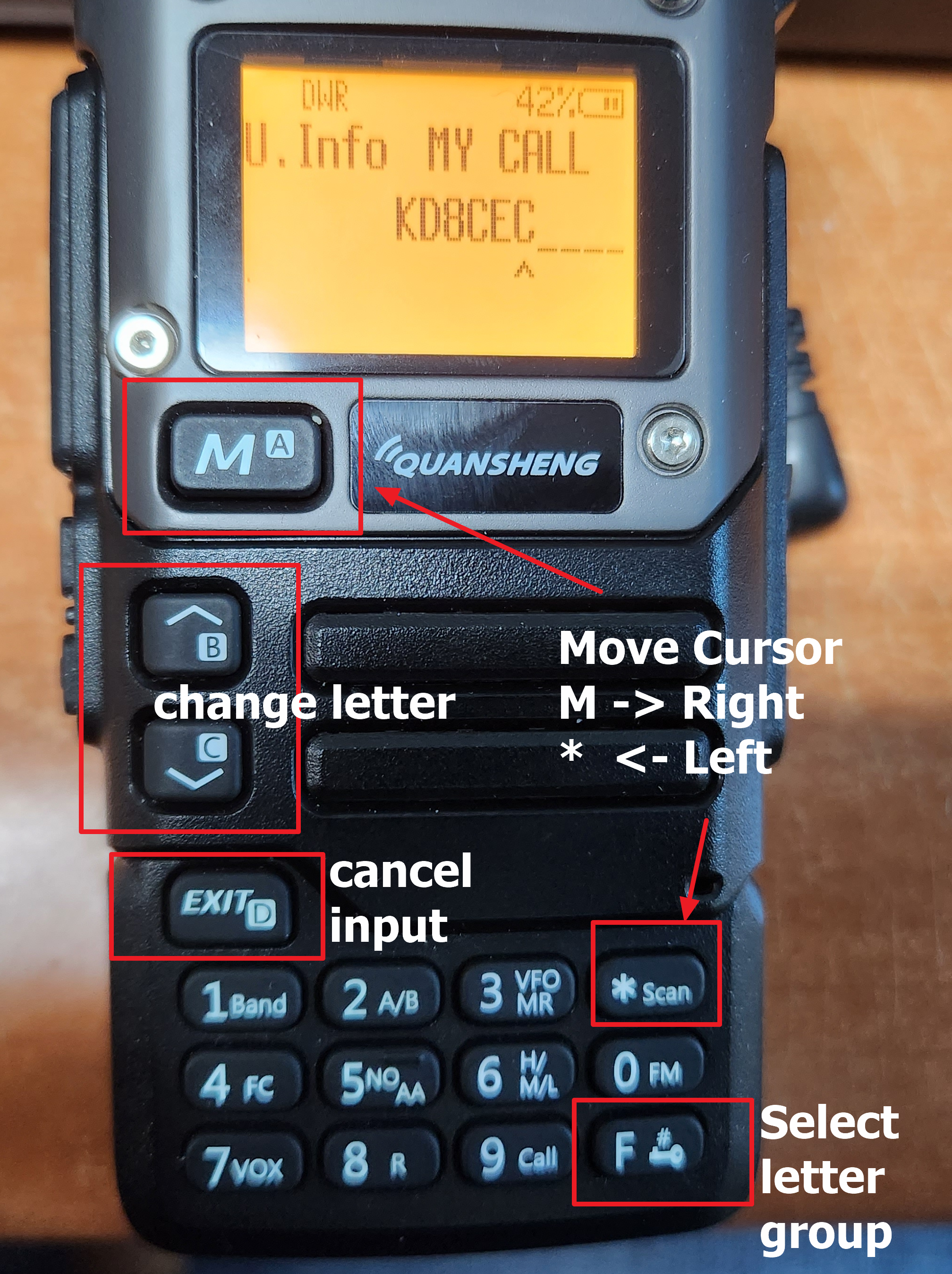
1.Improved text input
Most of the contents are the same as the existing firmware. I only did something very small. Since you will be using text input frequently in the firmware (UV-K5 CEC version), changed it to make input more convenient. I only changed the function of the * button and the F button very slightly.
Once you select a letter, press the 'M' button to move to the next step. If you enter something incorrectly, you can press * to go back.
Press 'F' to change the input to uppercase, lowercase, _ (do not enter), or Space
For example, when you want to input the capital letter 'C', press the 'F' key to make it 'A', then press the UP KEY twice to make 'C' appear, then press the 'M' button to move to the right
2.Text settings
The available channels have been reduced from 200 to 170, I needed some text related settings and decided to use the channel name fields from channel 171 to channel 200
It will remain compatible with other firmware. If you delete my firmware and install another firmware, only the channel name will be changed
U.Info - > My Call : your call sign
U.Info - > My Name : your name
U.Info - > My Grid : your grid (using https://www.qrz.com/gridmapper)
You only need to enter 4 digits (Example : EM37)
U.Info - > DX Call : Call sign of the other party (This is used on SSTV and CW Eleckeyer)
U.Info - > DX Name : Name of the other party (This is used on SSTV and CW Eleckeyer)
And there are a few additional text items (CW message, GPS Location and etc). Enter whatever you want to enter.
3.SSTV transmission function
SSTV supports Martin v1. Due to limitations in flash memory space for writing firmware, various functions could not be included. However, I am also considering adding the ability for SSTV users to create their own templates if they wish.
(The implementation included scottie and PD90 protocols, but they were excluded when compiling due to lack of firmware space)
The text to be included in the picture must be entered in SSTV M1 (SSTV message 1) in the text input menu (U.Info).
Please enter your message on M2 as well. Usually, it is good to input the signal status of the other station.
Enter the T.SSTV menu.
Press the 'M' button to select CQ.
And if you press it again, SSTV will be transmitted
When transmitting a QSO, the call sign of the other station is displayed. In the text input menu, enter the call sign of the other station in advance in the DX CALL item.
The LCD menu is just for a bit of fun. When you press this button, it is transmitted as a radio wave to the screen of your UV-K5 10 seconds later. Of course, your call sign will be overlaid on the screen
I have ported a few games to UV-K5 and will release them later when I have the chance. It might be fun to transmit your Tetris screen and scores to SSTV. LOL
Additional: I thought a lot about resolution when transmitting SSTV. If this is not a toy but a function that is actually used, I thought it should have a resolution that can be read when transmitted with a 5W radio rather than being flashy.
From the next version, versions with experimental elements will be published. The source code for this version has been released together. Versions 0.3 to 0.9 are in the development stage, and I will release the source code together with version 1.0
1. Version 0.1C added a function that can detect signals even while the frequency is moving.
This feature is supported by most radios except toy radios. It's like turning the radio dial to tune the frequency. It is the same as turning the knob on an HF radio to find a signal.
Select Live.S from the menu.
If you select "LIVE", you can detect the signal even when moving quickly by pressing the UP/DOWN button on the keypad.
If you select "LIVE+", it detects signals even when you move quickly by pressing the UP/DOWN buttons on the keypad and displays the detected signals in a graph at the bottom of the screen.
Please click below to watch the introduction video (Please turn on the subtitles)
2.Add Mhz button function
This function is not necessary for general VHF/UHF radios. However, it is a function that most radios that can receive shortwave bands have.
When you want to enter 28.050, just enter in the following order: 2 -> 8 -> * -> 0 -> 5 -> 0.
All basic features of this source are based on egzummer's date of January 2, 2024.
I worked on the first firmware. I did what was requested by the user. Alternatively, functions that are not greatly needed in amateur radio were changed to those that are needed in amateur radio.
This version is stable because no major modifications have been made to the existing source code.
Change the environment so that it can be used in Visual Studio Code (win_make.bat, makefile option ...)
Remove some unnecessary variables for operation
Changed the BCL function to be selectable at the compilation stage. (Because BCL is not often used in amateur radio), If you need the BCL function, just set the compilation options. (ENABLE_BCL ?= 0)
Changed all band TX activation from 10 times to once (this can also be operated in the old form in the makefile) (This is because you working in the Hiddel Menu anyway)
The 350TX, 350EN, and 500TX functions have been changed to amateur radio bands. Even if TX 350 and TX 500 are ENABLE, they only operate under certain conditions. (Default Range Mode) , In countries where the TX function must be tested for radio use, TX on all frequencies must be within range. To receive permission for 900Mhz or 1.2Ghz, just enable TX900 and (TX126 OR TX127 - Each country has different licensed frequency bands. Just choose the band that suits you.)
2.Introducing what I have been experimenting with for several weeks.
The features below are not yet included in the firmware. I plan to include them all before my vacation ends.
2.1 By simply entering values into the registers, no modulation is performed and it operates in CW mode.
2.2 CW (A1A), CW (F2A) implementation
2.3 Test whether AM and SSB signals can be synthesized with MCU.
2.4 CAT communication implementation
2.5 CW reception performance and memory keyer built into the radio
There have been some changes to the DMR node recently.
This version changes only those related to the recently changed DMR node. If you normally use Version 1.0 or Version 0.95, no upgrade is required.
DVPi uses the USRP Client protocol. When you install and use DVSwitch, you must read and comply with the license that appears. The user is responsible for the license for the use of DVPi.
2.What was added in Version 1.03 (from Version 1.0)
-To reduce user confusion, the MMDVM password change function has been removed.
If the DMR's BM password has been changed, it can be changed on the DVSwitch Settings Change screen.
- It is not a function you use. Changed the TX/RX frequency of MMDVM to the same frequency. This is because the new DMR rule may not work if the frequency is different.
3.How to Install
There is a detailed explanation about more detailed installation method and H/W configuration on my blog.
The following explains how to download and configure to use DVPi. Please refer to another post for more details.
3.1 Download
Download the dvpi_103.zip and dvpimanager_103.zip files from the download link.
Unzip the downloaded files (dvpi_103.zip, dvpimanager_103.zip)
3.2 Write the dvpi_103.img file to the SD card.
Formatting the SD card is not mandatory. When I apply the image file to the SD card, sometimes an error occurs, so I format it first.
Apply the dvpi_103.img file to the SD card with Win32Disk Imager.
After completion, remove the SD card and insert it into the Raspberry Pi of the DVPi.
Connect power to the DVPi. (power on DVPi)
Sometimes, depending on the LCD, the screen is turned upside down, You can reverse the top and bottom of the screen in DVPi Manager.
At the time of the first boot, because there is no setting, it is not possible to log in.
3.3 Find DVPi IP Address
The Raspberry Pi image used in DVPi is automatically assigned an IP (using DHCP Server).
You can use the DVPi Manager to find out the IP of the DVPi.
Run DVPi Manager -> Click the 'Find DVPi' Button
Click the 'Find' Button
(If multiple LAN cards are installed in your computer, you must select the IP address of your computer before clicking the 'Find' button)
I have 3 DVPi and they are all found. Once you have found the IP of the DVPi you can use ssh.
DVPi can be accessed with ssh id: pi, password: dvpi
3.4 Installing DVSwitch and Setting up DVSwitch
(DVSwitch installation is only necessary to embed DVSwitch into DVPi)
Execute DVPi Manager -> Input DVPi IP Address -> Click the 'Connect' Button
Click the 'Easy setup of installed DV Switch'
To embed DVSwitch into DVPi, you only need to execute 4 commands. The four commands are explained in the center of the screen.
Rutn the SSH Client as putty
Login ID : pi, Passwor d: dvpi
Execute the commands described in DVPi Manager one by one.
It is convenient to use copy and paste.
In the case of putty, you can copy and paste multiple lines at once.
Execute 'sudo apt-get install -y dvswitch'
If all 4 commands were executed, your DVPi would have DVSwitch installed.
Setting up DVSwitch is easy with just a few entries.
Enter your callsign and DMR ID,
Unique ID is your Hotspot number that is unique. Any number you don't use is fine.
Choose Brand Meister Host, It is recommended to choose a server in your country.
(The US1 server that was set as the default until DVPi Version 1.0 is no longer operated)
If you have changed your password in Brand Meister, you must change the password field to your password.
The BM password can be changed here.
Enter the changed password.
Enter the Location field, the rest is not required, but it is strongly recommended to enter latitude and longitude.
Click the 'Apply All Setting' button.
The screen below is displayed and the operation takes about 1 minute.
When all settings are completed, the following message is displayed.
After rebooting DVPi, you should be connected to the DVSwitch server as shown below.
You can also check your Hotspot list if you log in to Brand Meister. I set the unique number 37 and it was displayed as follows.
3.5 flip the screen upside down
(This is only necessary if the screen is upside down like me. If your screen appears normally, this step is not necessary.)
Click the 'DVPi Basic Setup'
Click the '3.5 LCD 180 (upside down)' Button click
After rebooting, it will display normally as shown below.
3.6 Using DVPi
(For detailed usage and hardware configuration, please refer to other posts)
I will configure the DVPi to Dual Mode. Since it's in Single Mode now, only VFOA works.
Since VFOB copies the settings of VFOA as it is, it is necessary to test whether VFOA works well.
Change TG
Reception is good. You have to test the transmission. If you are using D-Star, I recommend testing up to D-Star.
3.7 Dual Mode Settings
Connect to DVPi via SSH Client
Execute the setdvs2.sh command.
(./setdvs2.sh new unique number, The unique number is the new Hotspot number.
ex ./setdvs2.sh 38)
You can ignore the following error messages during script execution. (This is because it is a command to delete if it is already installed)
When all execution is completed, it asks if you want to reboot as follows.
No reboot required. This is because DVPi Manager will cause the DVPi to reboot.
Run DVPI manager
Click the 'DVPi Basic Setup'
After selecting Dual VFO as shown below, click the 'Apply All Setting' button.
(You may select 'Use Voice' if you wish to use the voice guidance function of DVPi)
When all settings are completed, DVPi automatically reboots.
After rebooting, DVPi operates in Dual Mode.
How to use DVPi's Dual Mode is described in detail in another post.
I tried changing the TG of VFO B.
3.8 DVPi's Hardware Settings
DVPi does not require any hardware other than the Raspberry Pi, sound card and LCD.
But for convenience, you can add things like buttons that you need.
How to add hardware to the DVPi is detailed in another post.
Run DVPi Manager
Click the 'Settings to use rotary encoder, PTT, and VOX functions' Button
In my case, I chose all of the below because I had a rotary encoder and buttons.
(If the direction of the rotary encoder is opposite, the numbers in the red square box below are interchanged)
When the activation selection for hardware is finished, click the 'Apply All Setting' button.
If the DVPi is equipped with a rotary encoder, it is possible to check who is in the TG as shown below.
4. conclusion
DVPi has quite a few features. In this post, I only set the settings for some of the features that are absolutely necessary for me.
Version 1.0 and Version 0.95 are the same. If you are using Version 0.95 you do not need to update to Version 1.0.
DVPiManager has some features added. If you want to use features added in Versio 1.0, you only need to download dvpimanager.
DVPi uses the USRP Client protocol. When you install and use DVSwitch, you must read and comply with the license that appears. The user is responsible for the license for the use of DVPi.
Version 0.95 is a candidate version of Version 1.0 so, If there are no major problems you won't need to upgrade to Version 1.0
DVPi uses the USRP Client protocol. When you install and use DVSwitch, you must read and comply with the license that appears. The user is responsible for the license for the use of DVPi.
The goal is 10 hours of nondisruptive operation, but most of the test devices have been running for more than 24 hours. The main purpose of Versoin 1.0 is stabilization
I tested stability for about 2 weeks with a few people who helped me with the test.
2.2 Viewing the status of other Talkgroup is now possible again. (bottom line in TG Button)
I have created a server program that manages the DMR Talkgroup status. Several Amateur radio operator are servicing the server.
You don't have to do anything for this.
You can use this feature without doing any work. But if the Talkgroup Status server doesn't work, you can choose another server.
2.3.ThumbDV settings are now supported by DVPiManager.
When you use DVPi in Dual Mode, you can set VFOA and VFOB independently.
2.4 DVSwitch 1.6.0 is supported if you install DVSwitch on DVPi (builtin DVSwitch)
2.5 Several modifications were made for the use of D-STAR. (Ex: Support Unlink Button in D-Star Mode)
2.6 Recording function has been added. It was added in Version 0.88
When you press the record button, the sound output from the speaker is recorded. You can export to Wav file from DVPi Manager.
2.7 And Minor bugs have been fixed and minor UI changes.
- The color of the underline of the TG button has been changed to make it easier to see. As the QSO time increases, it changes from blue to white.
- The display method of the LOG Window on the right side of the screen has been changed. Since the callsign is the most important, changed it to a way that all callsign letter appear. (display order = minute callsign: Talkggroup )
- more...
3.conclusion
The horse.brandmeister.network server was down, so it took time to create a replacement service. Also, for Version 1.0, I have been testing it for quite a while to increase stability.
Perhaps this version will be Version 1.0 without much change.
If you are using Version 0.95 you do not need to update to Version 1.0.