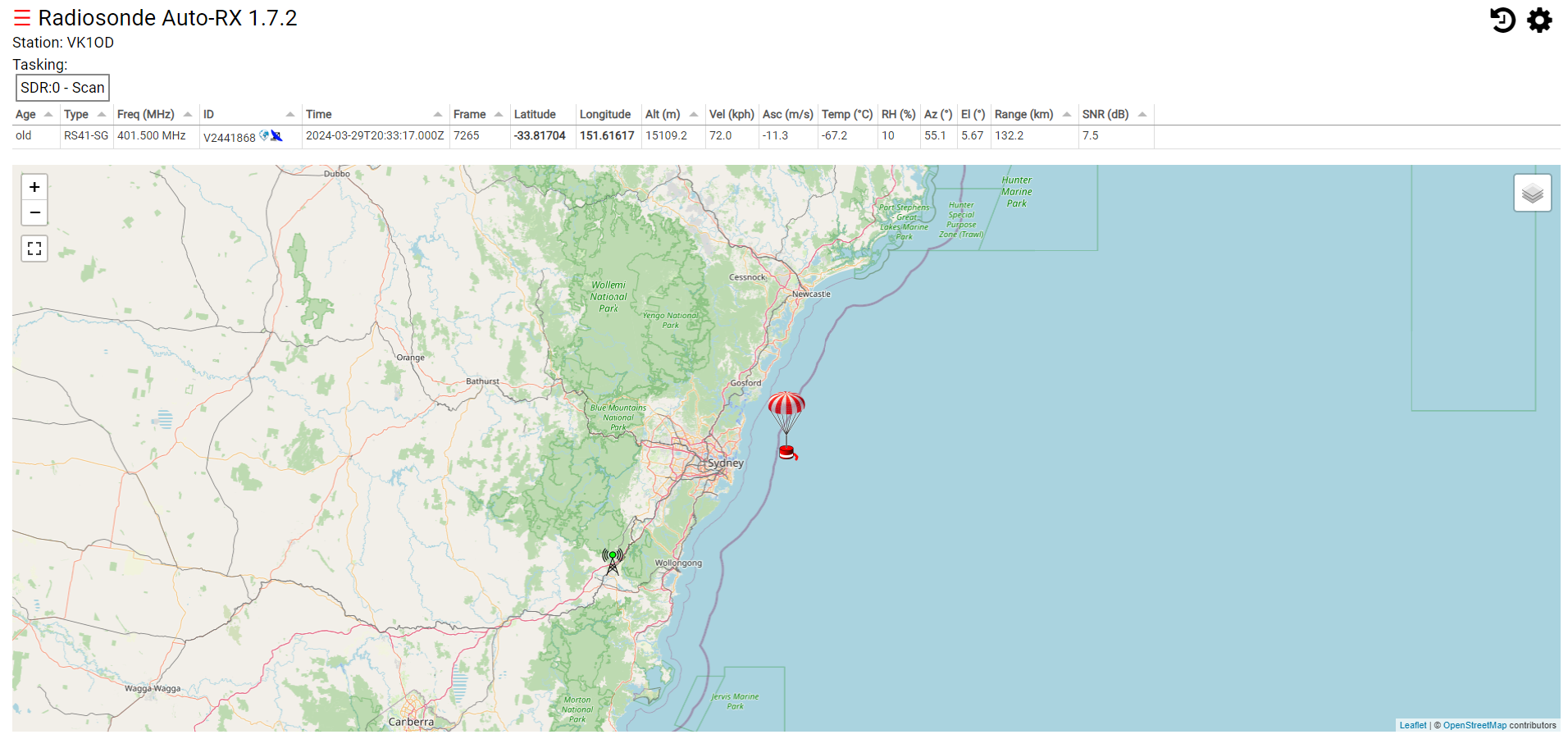
Radiosonde Auto-RX 1.7.2 is a software package for downloading data from a weather balloon.
Above is a screenshot from Radiosonde Auto-RX 1.7.2.
A friend has experienced problems where his RTL-SDR dongle stops working periodically. This is apparently a known problem if the power supply voltage is low.
This article documents current and voltage at the USB power jack on the RPi of:
RPi 3B+ running Radiosonde Auto-RX 1.7.2;
RTL-SDR v3 dongle on a 200mm USB extension cable; and
‘official’ RPi 3+ (5.1V 2.5A) power supply.
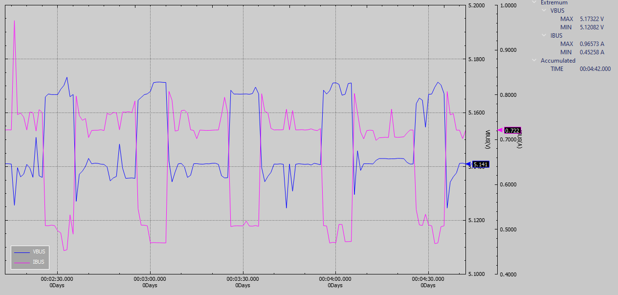
The RPi3B+ is a problem, it spews log messages when the supply falls much below 5V, and IIRC even if the voltage is withing the USB standards. That said, my understanding is that in this scenario, it is the RTL-SDR that may be the intolerant one.
Above is a capture of voltage and current when the system is in the scanning mode. Periodically it launches a scan which drives system current up which causes a small sag in voltage.
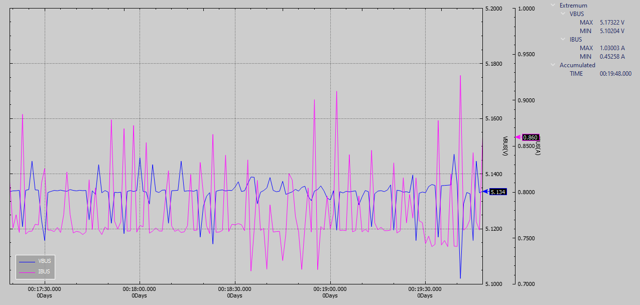
Above is a scan when a balloon is being decoded, quite a different current profile.
Note that the measurements relate to the hardware configuration described, and to some extent the software build on the RPi.
Version 1.0 and Version 0.95 are the same. If you are using Version 0.95 you do not need to update to Version 1.0.
DVPiManager has some features added. If you want to use features added in Versio 1.0, you only need to download dvpimanager.
DVPi uses the USRP Client protocol. When you install and use DVSwitch, you must read and comply with the license that appears. The user is responsible for the license for the use of DVPi.
You can use D-Star only by checking whether to 'Enable D-Star' in DVPi Manager.
Touch the 'More' button -> Touch the 'Mode (displayed DMR or DStar)' Button
The video below shows the activation of D-Star during the initial installation of DVPi.
If you are already using D-Star, you will not be able to use it on two at the same time. If you want to use D-Star in DVPi, you need to log off in another device. If anyone has solved this problem, please tell me.
2.2 Dual Mode
You can use two VFOs in the same way as a conventional VHF/UHF transceiver.
You can use two DVSwitch servers or DVLink. Or, if you operate DVPi as Standalone, you can create session 2 by copying the existing installed DVSwitch in DVPi.
If you are using DVPi stand alone, just run the setdvs2.sh command to copy the DVSwitch installed in DVPi and add a new session.
Unique ID values must be entered differently from existing values.
Example)
Session 1 Unique ID is 51
Sesssion 2 Unique ID is 58
In order to distinguish Hotspot in DMR network, you must use different Unique ID.
Select Dual VFO in DVPi Manager.
It will operate in Dual Mode as shown below.
Important Point: If you use DVPi stand alone, D-Star only works on VFO A.
The video below shows how to create Session 2 by copying the DVSwitch installed in DVPi and operate DVPi as Dual Mode.
2.3 Function Switch 2
Function Switch2 can be used as Mode change or VFO change according to your selection.
Example of using Function Switch2 as a mode change switch
3.conclusion
The host.brandmeister.network server is not serviced, and the entire Talkgroup status can no longer be retrieved. So, the underline of DVPi's Talkgroup Button is disabled.
I'm trying to restore that functionality in Version 0.9. If we connect to brandmester.network directly, it will generate quite a lot of traffic. This is a problem for us as well, but it could also cause problems on the brandmeister.network server.
So I am thinking of building a separate server to minimize traffic.
Until version 1.0, we plan to stabilize without adding features.
Thank you for using and testing.
We are always grateful to the DVSwitch team for implementing most of the features.
Since DVPi 0.7, a status line has been added inside the Talkg group button.
This post will explain the Talk group status line.
1.Talk group Button
The buttons in the red box below are the buttons to change the Talkgroup.
There are three background colors for the Talkg group button as shown below.
DarkGray : Normal talk gorup
Orange : Current Talk group
Dark Orange : Talk group selected by moving an analog encoder
2.Status Line in Talkg group Button
The Talk group button contains a status line. Numbers 262 and 91 below are blue and the rest are gray.
Let’s explore if there are other colors. Talk group 914 is Light Blue.
Talk group 216 is White Color
Below is what the color of the Status Line means.
Blue : Talk group currently in conversation
Light blue: TG communicated within 5 minutes
Yellow : TG communicated within 10 minutes
White : It has been more than 10 minutes
Gray : Where there is no contact record
3. View users accessing the Talkg group
If you connect the rotary encoder to DVPi, you will see a screen like the one below after 1 second of moving.
The time displayed in'Last' is the last time the PTT was pressed in the corresponding Talk group.
4 Update of Talk group status
4.1 Automatic update of Talk group status
Talk groups are automatically updated on the Internet. By default, it is set to be updated every 1 minute and 30 seconds.
Connect to DVPi Manager as shown below and click the'Userful features' button.
The Update Interval value in the red box is the cycle to update the Talk group status.
Set it to '0' if you don't want to automatically update the Talkgroup status automatically. It may be better to set it to '0' if you have a bad internet environment.
The number '1' means 30 seconds.
Set it to 4 if you want to refresh it every 3 minutes
Set it to 10 if you want to refresh it every 5 minutes
4.2 Manually updating the Talk group status
If it is set not to be automatically updated or you want to know the Talkgroup status immediately, click the'TG Info Get' button below.
5.Updating user information
If there are many users who are not displayed as a call sign as shown below, please update the'User DB'.
It is recommended to update the'User DB' at least once a month.
DVSwitch Builtin on DVPi (DVPi standalone setup) without DVPi manager
DVPi is a client program that communicates with DVSwitch.Please be aware of the licenses that arise when installing and using DVSwitch. Follow the instructions that appear when installing DVSwitch or the instructions on the DVSwitch site. I am not responsible for DVSwitch and the programs contained in DVSwitch, and I am not responsible for the use of DVPi. Please use it only if you agree to this.
If you are using an existing DVSwitch server or DVLink server, you do not need to read this post. Follow the DVSwitch group's instructions on how to install DVSwitch on DVPi. I just make the setup of the installed DVSwitch a little easier.
I will explain how to set up DVSwitch to DVPi in two ways. The first is to use DVPi Manager and the second is to not use DVPi Manager.
This post explains how to edit ini file directly without DVPi manager. If you want to easily configure the DVPi manager, please refer to the previous post.
As of DVPi Version 0.7, a script to easily set up DVSwitch has been included.
The video is linked at the bottom of this article.
1.Required
1.1 Installed DVPi and You need to know the DVPi's IP address.
Do not edit the Unique ID. However, if you use two or more Standalone DVPi, please enter different values.
Ex ) DVPi #1 : 57, DVPi #2 : 58, DVPi #3 : 59
This is the value by which the DMR network identifies your device.
If you have entered the call sign and DMR ID, you can perform DMR communication.
However, if you change to the BM server closest to you, you can use a much more stable DMR. Please replace it with the one closest to your area from the BM List below.
This is the information displayed to other users. If you enter your latitude and longitude, and your city and country, you will be a good DMR communication.
If you don't know the latitude and longitude of where you live, open Google Maps and click the mouse. The latitude and longitude of the clicked place will appear at the bottom.
important : If you don't use Ambe Server, Change 'USE_EMUL=True'
Depending on the DVSwitch version, you may not need to select it, but there are cases where you have to.
Save the setdvs.ini file when everything has been modified.
4. Execute setdvs.sh
Remove the micro SD card from the computer, plug it into the DVPi, and turn on the DVPi.
Run putty again.
id : pi
password : dvpi
type ./setdvs.sh press Enter key
The script will be executed as shown below.
The information you entered in setdvs.ini is displayed. After checking, press the y key.
When everything is done, it will be displayed as below. Press y.
When everything is done, the Raspberry pi reboots and all connections are disconnected. Don't worry, it's not an error.
5. Standalone DVPi (Builtin DVSwitch)
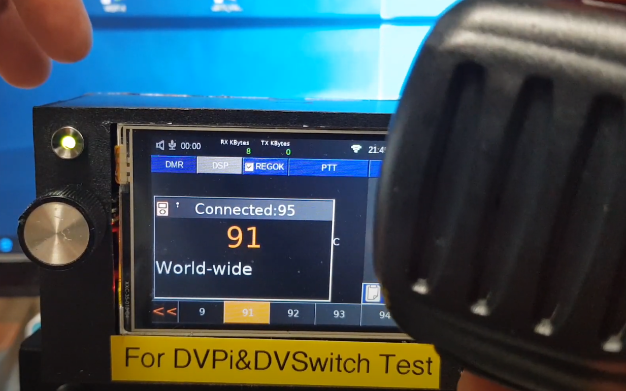
When rebooting, REGOK will be displayed as below.
If it is set for the first time, there are cases in which you have to press PTT once to operate normally (your information is registered in the BM server)
When I changed to Talk group 91, I was able to hear the voices being communicated.
If you make any modifications related to DVSwitch, it will be set automatically by executing ./setdvs.sh after editing setdvs.ini file anytime.
You can easily change the DVSwitch settings at any time by running steps 3 (Edit setdvs.ini) and 4 (execute setdvs.sh) above.
DVSwitch Builtin on DVPi (DVPi standalone setup) using DVPi Manager
DVPi is a client program that communicates with DVSwitch.Please be aware of the licenses that arise when installing and using DVSwitch. Follow the instructions that appear when installing DVSwitch or the instructions on the DVSwitch site. I am not responsible for DVSwitch and the programs contained in DVSwitch, and I am not responsible for the use of DVPi. Please use it only if you agree to this.
If you are using an existing DVSwitch server or DVLink server, you do not need to read this post. Follow the DVSwitch group's instructions on how to install DVSwitch on DVPi. I just make the setup of the installed DVSwitch a little easier.
I will explain how to set up DVSwitch to DVPi in two ways. The first is to use DVPi Manager and the second is to not use DVPi Manager.
This post will use DVPi Manager to setup DVSwitch. If you are having trouble using DVPi Manager, please refer to the following post.
As of DVPi Version 0.7, a script to easily set up DVSwitch has been included.
1.Required program
1.1 dvpimanager.exe
Included in the dvpi release distribution. In previous posts, there is a way to download and unzip it.
1.2 ssh terminal program as putty.exe
If you are using Windows I recommend using putty.exe. You can download it from the link below.
If you are using Linux, there is no need to install a separate program
You can connect to pi@dvpi ipaddress from a Linux terminal.
2. Install DVSwitch
2.1 Execute dvpimanager.exe and connect to DVPi
Double click the 'dvpimanager.exe'
or mono dvpimanager.exe on (linux or mac)
Enter the DVPi's IP address, then click the 'Connect' button
(There are many ways to find DVPi's IP. Some examples can be found in previous posts)
2.2 Instrall DVSwitch
If the connection is successful, the following screen appears.
Click the 'Easy setup of installed DVSwitch' Button
DVPi works based on DVSwitch. With the dedication of many DVSwitch developers, DVPi can be used. Install using the installation method provided by the DVSwitch group.
Below is the current installation method.
Before proceeding, launch an SSH terminal. You can use any SSH terminal. I used putty.
When the following message appears, click the'Yes' button.
id : pi, Password : dvpi
You need to run 4 commands in the SSH terminal. I recommend copying and pasting rather than typing directly.
Copy the first command.
Paste it into putty. (Press the right mouse button to paste automatically)
Press the 'enter Key' to execute the first command.
Copy the second command.
Paste it into the SSH terminal (as putty.exe) and press Enter.
Copy the third command.
Paste it into the SSH terminal (as putty.exe) and press Enter.
It is completed in about 1 minute.
Copy the fourth command.
Paste it into the SSH terminal (as putty.exe) and press Enter.
It is completed in about 1 minute.
DVSwitch installation is complete on your Raspberry Pi.
Installation is very simple. This is the dedication of the DVSwitch developers.
If you get an error while installing DVSwitch, try it elsewhere. I've found a few cases where it doesn't work depending on your internet provider.
2.3 Setting up DVSwitch
There are only two that you must enter. However, it is recommended to enter additional information.
Enter your Call sign and DMR ID. You can create a DMR ID at the site below.
Do not edit the Unique ID. However, if you use two or more Standalone DVPi, please enter different values.
Ex ) DVPi #1 : 57, DVPi #2 : 58, DVPi #3 : 59
This is the value by which the DMR network identifies your device.
There is no need to modify this part either. However, if you change to the BM server closest to you, you can use a much more stable DMR.
Click the 'Find BM in my Country' button
Select a server in your country or region close to you and click OK.
This is the information displayed to other users. If you enter your latitude and longitude, and your city and country, you will be a good DMR communication.
If you don't know the latitude and longitude of where you live, open Google Maps and click the mouse. The latitude and longitude of the clicked place will appear at the bottom.
When you have entered all the values, click the'Apply All Setting' button.
You will see a message similar to the one below.
When everything is done, the Raspberry pi reboots and all connections are disconnected. Don't worry, it's not an error.
The SSH terminal will also display a message stating that the connection has been lost. This is also not an error, so don't worry.
3. Standalone DVPi (Builtin DVSwitch)
When rebooting, REGOK will be displayed as below.
I changed the Talk group to 91. The communication tone was immediately received.
If it is set for the first time, there are cases in which you have to press PTT once to operate normally (your information is registered in the BM server)
Congratulations. Now, with only one DVPi (DVSwitch Builtin) , DMR communication is possible anywhere with the Internet.
DVPi can be used without any additional hardware. A Raspberry Pi, 3.5" LCD and USB sound card are enough for DMR communication. However, if you want to use DVPi more conveniently, or if you like to make it, I think it is good to configure the hardware as follows.
This hardware is the final version. No hardware will be added to the DVPi anymore.
I would like to introduce the DVPi hardware expansion into several types. You can create DVPi the way you want.
1. Use without any additional hardware
I also recommend this method. The simplest. You can create and use DVPi with just RPI, LCD, USB sound card.
Start DVPi Manager.
Click the 'Settings to use rotary encoder, PTT, and VOX...' button
Then, The DVPi's hardware configuration screen appears.
You should not select anything as shown in the screen below. This is the DVPi default setting screen.
2. PTT extension
To extend the external PTT to DVPi, you only need one 10K resistor and one switch.
Set it as follows. The encoder must be selected even if it is not used.
3. PTT extension (Safty)
To extend the external PTT to DVPi, you only need three 10K resistor and one switch.
This is to attach two pull-up resistors to an encoder that is not in use.
Set it as follows. The encoder must be selected even if it is not used.
4. Rotrary Encoder and PTT extension
You can use DVPi more conveniently with Rotary Encoder with switch , a switch and 4 10k resistors.
Below is the rotary encoder I use. It is a rotary encoder generally used by Arduino.
I did the following, but if you want to do it easily, you can apply a resistor directly to the rotary encoder.
Set it as follows.
5. Rotrary Encoder , PTT and Function Key extension
You can add a function key to use the submenu added in Version 0.7 or the Quick Menu function for the visually impaired.
Just like adding a PTT switch, just add one more switch.
Set it as follows.
6. LED extension for Receive Signal indication
I just added the LED function to the above circuit. If you don't need rotary encoder, PTT, function key function, you can use it by connecting only one LED and one resistor.
The LED will light up when voice is received.
Set it as follows. The encoder must be selected even if it is not used.
If you are not using PTT, Rotrary Encoder, Function Key, don't check all checkboxes, just check'Use RX Signal Out'.
The default value of RXOUT Delay is 15, but 3 is recommended when using LEDs. It will look a little active.
7. PC817 extension for Receive Signal indication
Everything is the same as in item 4 above. I just replaced the LED with PC187.
This is for external radio control. I experimented about this 3 times and it was quite satisfactory. I will be posting a separate article on this.
Yes. As you might guess, it is relaying digital and analog using an inexpensive analog radio. Use this only for your personal laboratory use.
Set it as follows. If you connect analog radio to DVPi, it is recommended to set RXOUT Delay value to 5~10.
8. Hardware GPIO number
GPIO numbers are used for all of the above settings. EX: ENC A = 25, ENC B= 24...
I configured the circuit as above, but if you want to use the GPIO for other purposes, you can connect it anywhere.
You can also connect the PTT switch to GPIO 21. In that case, you just need to set the PTT GPIO to 21.
Please refer to the GPIO number below. The GPIO number is based on WiringPi.
9. FM Transmitter Extenction
(Just use it for experimental purpose)
Not available on Raspberry Pi 4. only Raspberry PI 1,2,3
FM Transmitting programs existed on the Raspberry Pi from the past.
I changed the RpiNBFM source code to receive UDP data and send it through RF and included it in DVPi as a separate program. (named 'udptonfm') This source code will be posted on git.
This program uses Raspberry pi's DMA, but the program stops functioning frequently due to a conflict with another process. RF transmission stops about once every almost 5 minutes. However, since DVPi periodically restarts the process, the RF signal will be transmitted again after a while.
You should use this feature only for fun and experimental purposes.
You don't need any additional hardware to use this feature. Just change the settings as follows.
Click the Advanced Setting
Checked 'Using FM Transmitter using GPIO 4'
and Set you want Frequency (Khz)
You just need to set the frequency below 250Mhz.
2M, 10M, 11M are all possible.
Sending the radio a little further, If a 1m wire is connected to GPIO 4, radio waves are transmitted over a long distance.
you can alos adding the SMA connector as below.
Again, use FM transmission only for fun and experimental purposes. Periodically, the RF signal will be interrupted, and the DVPi may be down due to a heavy load on the CPU. Also, use it legally in your country's laws.
10.My final DVPi circuit.
Below is my final DVPi circuit.
Again, you don't have to add any hardware to the DVPi. I recommend it too.
It is recommended to keep the CPU temperature of the DVPi below 50 degrees. Just attach a small fan to the DVPi case.
Release DVPi 0.7 - Installing on Micro SD card & First boot DVPi
DVPi is a client program that communicates with DVSwitch.Please be aware of the licenses that arise when installing and using DVSwitch. Follow the instructions that appear when installing DVSwitch or the instructions on the DVSwitch site. I am not responsible for DVSwitch and the programs contained in DVSwitch, and I am not responsible for the use of DVPi. Please use it only if you agree to this.
This post applies to all versions released after Version 0.7, It's just the version that's attached to the file name. In this post, it's all about downloading the file and finding out the DVPi's IP.
This post also includes how to download and run DVPi Manager. This post applies to all DVPi versions.
0.Changed in Version 0.7A (changed 0.7 (filename 0.79) -> 0.7A)
1.When DVSwitch is automatically configured by script, DMR User information is additionally written to DVSwitch.ini (description), MMDVM_Bridge.ini (qrz.com/user callsign) :Thanks DS5QDR
2. Added 1 line 127.0.0.1 dvpi to /etc/hostname :Thanks G4ZAL
3.Fixed a bug where the sender information is not changed on the screen when the sender is changed quickly (within 200ms)
you have already installed Version 0.7 (filename 0.79) and you have no problems using it, you do not necessarily need to update to Version 0.7A
0. Changed in Version 0.7 (The added main features will be posted as separate posts)
1.Several bug fixes
-Fixed an issue where the encoder switch was closed by pressing the encoder switch in the keypad window.
- Fixed the problem that DVPi was not sometimes executed after booting from RPI4(I delayed the time to try to connect to the Analog Bridge 5 seconds after booting.)
2.Added Function Button 3.Added Sub menu (+More) Squelch mode Unlink function Auto Log Send ( If you run a program like Log4Om on your computer, the log is automatically transferred.) Enabled / Disabled VOX Show RMS for Setting VOX
4.Added VOX 5.CPU Temperature check -> display on main window 6.Voice guidance 7.Quick Menu using Function Key 8.Mode for the visually impaired 9.Separate the audio processing part into a separate thread 10. Show other Talkgroup status 11.Added several options that can be used as repeaters by connecting analog radios. 12.DVPiManager program additional development (To easily manage DVPi)
1.Download - DVPi image file and Extract
1.1 Download DVPi Image file You can check the latest version of DVPi file by clicking below.
dvpi_(versionnumber).zip is the DVPi image file. From DVPi Version 0.7, DVPi Manager is released together.
ex) dvpi_079.zip : DVPi image file
Click the dvpi_079.zip
Download dvpi_079.zip
1.2.Extract dvpi image file
2.Write image file to SD card
2.1.Insert the Micro SD card into the card reader.
2.2 Run the Image Writer program.
- Win32DiskImager (I Used)
- Raspberry Pi imager for Window, macOS, Ubuntu
- Any other program that can write image files to SD card can be used.
Select the drive of the microSD card. & Select dvpi Image file.
Check the selected DVPi Image file
2.3 Write Image file to Micro SD Card
Click the Write
Click the Yes after check device(drive) and image file
Image file write complete
3.Insert SD card into Raspberry pi and boot
Insert Micro SD Card to Raspberry Pi
Connect power to the Raspberry Pi.
The booting screen appears.
Even if the screen is upside down, ignore it. We will set it up later
After initial booting, it is displayed as not being connected as in the picture above.
Even if the screen is upside down, ignore it. We will set it up later
4.Finding the DVPi's IP
There are many ways to find out the DVPi's IP. Skip this part if you already know how.
In this post, I will introduce some ways to find out DVPi.
You can choose one of the various methods below and use it. Either way, you can find out the DVPi's IP address.
4.1 Finding IP Address in DVPi Program
Click the 'Menu' Button
Click the 'View IP' Button
As above, the IP address will be displayed on the LCD screen. Make a note of the printed IP address.
After checking the IP address, touch the'Return to Main' button to return to the Main screen.
4.2 Find DVPi IP on router management screen
Most routers have a DHCP check function.
Refer to the router's manual
4.3 Using ping command
From DVPi Version 0.7, the hostname of DVPI has been changed to dvpi.
You can check the dvpi's ip address with the 'ping -4 dvpi' command. If dvpi is more than 2 units, this method cannot be used.
5.Download DVPi Manager and try it for the first time (find DVPi IP Address)
5.1 Download 'DVPi Manager'
When DVPi new version is released, dvpimanager will be released together.
Click the dvpimanager_v{version number}.zip
ex)dvpimanager_v079.zip
5.2 Extract dvpimanager file
Unzip the manager file.
When DVPi Manager is uncompressed, there are two files.
Double click dvpimanager.exe to run dvpi Managerment.
5.3 Try DVPi Manager
If you've already found out the DVPi's IP address, you won't need it.
Click the 'Find DVPi' button
Click the 'Find' Button
Wait a while and you will find DVPi. If you use more than 2 DVPi, it will be useful.
Double-click the DVPi found and it will be automatically entered in the main window.
If you already know the DVPi's IP address, enter it in the IP address field as shown below.
5.4 Using DVPi Manager on Linux
DVPi Manager was written based on .net framework 4.0.
On Linux, install mono by typing sudo apt-get install mono-complete
You can run dvpimanager.exe with the command below.
mono dvpimanager.exe
I don't have a MAC, but I expect it will run the same through a mono install. If someone succeeds, tell me.
5.5 About DVPi Manager
DVPi Manaer just helps you set up DVPi. It doesn't matter if DVPi Manager doesn't work well in your computer environment. This is because you can directly edit the .ini file as before.
DVPi uses two files, the dvpi.ini file and the setdvs.ini file. If you edit these two files yourself, you don't need DVPi Manager.
Again, don't worry if the DVPi Manager doesn't run well on your computer
I will make a video for this post and post it on YouTube. (Next monday)
Describes the settings for DVPi audio input/output. If you are familiar with Linux, you probably already know. In particular, if you are transmitting too loud or too small when you are TX Mode, be sure to read this article.
This is very important for using DVPi well, Let me explain how I set it up.
1.Connection of sound-related devices
DVPi uses a USB sound card. Below is the USB sound card I use.
You may use an external speaker. If you have a spare computer speaker, you can use it as is. Just connect the external speakers to the sound card's headphone connector.
However, I decided to connect the small amplifier and the speaker directly to embed it in the case.
Audio Out and In are connected as shown below. GND is common, so only one is connected.
I have used an amplifier like the LM386 so far. I was looking for an easy way to make it and found the product below. As a 5Volt amplifier for less than $1, I was quite satisfied.
I bought PAM8403, but you can use what you can easily buy around you.
It is equipped with a variable resistor, making it easier to use.
I decided to use only one channel. That's enough.
2.DVPi Audio In/Out Tuning (It is important)
To use DVPi well, please set it up once.
If your Raspberry pi or sound card is replaced, you will need to set it up again.
2.1 Execute putty.exe
putty.exe can be downloaded from the Internet.
You can find the IP assigned to DVPi by dhcp in DVPi's Config window.
Enter the IP address of your DVPi and click the Open button.
Perhaps the first time you connect to your DVPi with Putty, you will get the following warning. Ignore and click Yes.
2.2 Login SSH (putty.exe)
Login as (ID): pi
Password : dvpi
If login is successful, the screen below appears.
2.3 Execute alsamixer and Select 'USB Sound Card'
Type alsamixer and Press the 'Enter' Key
The screen below will appear.
Press F6 on your keyboard.
The sound card selection window appears as shown below.
Press the arrow keys (Down) on the keyboard to select'USB Audio Device'.
2.4 Adjust 'Speaker' and 'Capture'
Then, the screen to set the volume of'USB Sound Card' appears as shown below.
When the speaker is selected, press the up or down arrow keys on the keyboard to change the speaker volume.
I recommend setting the speaker volume to 90% or higher. You can adjust the actual volume through the variable resistance of the amplifier.
Press'F5' to adjust the volume of the microphone connected to the DVPi.
Press'F5' on the keyboard.
The'Capture' item is also displayed as shown below.
Press the right button of the arrow keys on the keyboard to move to CAPTURE.
Press the up and down arrow keys to select the volume that is right for you.
(Caution: You do not need to adjust the MIC displayed in the middle)
When all adjustments are done, press the'ESC' button to exit.
On the Internet, it is recommended to run the 'sudo alsactl store' command after adjusting the volume.
Enter'sudo alsactl store' and press enter Key.
3.conclusion
I set the audio out to 100% (Speaker : 100) and then adjust the volume using the variable resistor connected to the amplifier. This works pretty good.
I first set the MIC (Capture) volume to medium, and then I attached a variable resistance to the MIC. The volume of the microphone was also adjusted through a variable resistor, but noise was generated in my case.
It is recommended that the microphone be adjusted as described above, preferably without variable resistance.
You just download the file and put it on your SD card.
Information about dvpi Image file:
id : pi
password : dvpi
enabled service : ssh, vnc, rdp enabled
network : dhcp (If you want to set a static IP or Wifi, you can find the setting method on the Internet.)
timezone : default (utc) - There is a setting method in the previous post.
sound card : You must use a USB sound card ($1 ~ $ 3)
(The sound card built into the RPI cannot be used)
default audio output volume : 100% (Adjust the volume using a variable resistor)
default audio input volume : 30% (Adjust the volume using a variable resistor)
After installing or replacing a new microphone, you can set it up through the alsamixer command.
How to use the alsamixer command will be explained in this document.
1.2 Download Image file
https://github.com/phdlee/dvpi/releases/tag/v0.5
Installation instructions are detailed in previous posts. (1.Installation and basic settings)
You just download the file and put it on your SD card.
1.3 Changed in Version 0.5
I will post a separate post for the added features that require detailed explanation.
(DSP, Send Log ...)
- Talk group change function from the keypad screen to the encoder
- The DSP function was simply modified for speed, etc.
- DSP to use only interpolation and LPF
- Added LPF_GAIN setting for volume increase when using LPF function
Increasing this number makes the sound louder when using the DSP function. However, if it is too loud, the sound may be distorted.
- By default, the DSP function is disabled.
When executed, it should look like this
If you are using the DSP function, touch the DSP button.
If you want to activate DSP function automatically when DVPi is executed, edit dvpi.ini file as below.
- Change font on call sign panel (to distinguish I, J, 1, etc.)
- Reserved settings for FUNC1, FUNC2, and FUNC3 extension keys (this is not used, it is only a reserve)
- Log record transmission function (using the format used by wsjt-x)
I know that I am not using LOG because it is DMR communication. Just applied what I made for my next project.It would be nice to use it for net control or memo.
(This will be explained in a separate post)
- The icons in the Configuration window have been rearranged.
- UserDB update function
Just Click the 'Update UserDB' Button in Configuration Window.
Then, Download user database from 'https://database.radioid.net/database/dumps'
and replace user.csv in DVPi
- Added * and # alphabets to the keypad window.
- Fixed some bugs
2.Encoder and PTT Installation
You can operate the DV mode more conveniently with a resistor and a rotary encoder.
Anyone who doesn't change Talk Group often can put a PTT switch with just one resistor.
2.1 Install PTT only
Soldering is required to connect 3.3 volts at the RPI. This is because the GPIO pin cannot be used because the LCD is connected.
When soldering to the board, be sure to turn off the power.
I installed PTT as below.
The Push-type PTT switch was connected to the Handy Microphone's PTT. Also, a toggle switch was additionally attached to the transceiver for more convenience.
2.2 Installing the rotary encoder
For this function, a rotary encoder and 3 resistors are required.
Just connect as below.
Below is the rotary encoder I use. It is a rotary encoder generally used by Arduino.
I did the following, but if you want to do it easily, you can apply a resistor directly to the rotary encoder.
2.3 Settings for PTT and encoder use
You need to enable PTT and encoder use in the dvpi.ini file.
Don't worry, it's very simple. Just activate it.
- Turn off DVPi and remove SDCard.
- Insert the SD card into your computer.
- Change both'USE_ENCODER' and'USE_PTT' to TRUE in the dvpi.ini file.
USE_ENCODER=TRUE
USE_PTT=TRUE
(before change)
(After Changed)
Your PTT and rotary encoder will now work. See the video below.
2.4 If the rotary encoder works in reverse
If your rotary encoder works, don't read this.
If the rotation of the rotary encoder works in reverse, there are two solutions.
Use the method you are comfortable with.
- First solution. I recommend this method. (Simple)
Swap the wires connected to the rotary encoder
I can't draw well, but I tried it once. Just swap the lines on both sides of the three connected as shown below.
- Second solution. I used this method because I already have a rotary encoder and RPI in the case.
In the dvpi.ini file, swap the values of items A and B
Example)
GPIO_ENCA=25
GPIO_ENCB=24
2.4 How to use a rotary encoder
Turning the encoder moves the TG list displayed at the bottom of the screen.
The TG list can be changed by clicking the blue button on the bottom right. Also, how to create and use the TG list was explained in a previous post.
When turning the encoder, the description of the selected TG is displayed at the bottom left. If you press the rotary encoder, it changes to the displayed TG.
(After push)
If the TG description window is displayed, pressing the PTT switch will switch to the displayed TG.
Even if the TG description window disappears, the TG selected using the rotary encoder remains. In the screen below, '91' is the current TG and '204' is the TG selected as the rotary encoder.
In this state, if you press the rotary encoder, it will switch to TG'204'.
Creating Network Transceiver using DVSwitch (or DVLink) #2.How to use
I upgraded DVPi to Version 0.4 today. The download location is the same. The functionality has not changed. It just changed the default volume of the Raspberry Pi's speakers and microphone. (Speaker : 100%, Mic : 80%), Also, the button position of the Menu Screen has been changed slightly.
1.Installation and basic settings (this article)
2.How to use 3.Rotary encoder, PTT installation 4.Advanced usage 5.Built-in DVSwitch (I will write this only when there is someone who wants it)
1.Main screen
The below is a standby screen.
1.1 Status bar
The uppermost part of the screen is the status bar.
- The speaker and microphone icons on the left indicate the transmission or reception status.
(When receiving, the speaker is activated.)
(The microphone is activated while transmitting.)
- RxBytes and TX Bytes indicate the amount of data transmitted.
- If you change the USE_CPUCHECK item in the dvpi.ini file to TRUE, the CPU utilization is displayed in the status bar.
EX) Click the 'Menu' Button -> Click 'Shutdown' -> Power off -> Remvove Micro SD Card from Raspberry pi -> Insert Micro SD-Card to your computer -> Edit dvpi.ini (below image) -> Remove Micro SD Card from you Computer -> Insert Micro sd card to Raspberry pi -> Power On
Displays CPU utilization on the screen.
For reference, the following is the CPU usage when receiving voice while the external DVSwitch is connected.
In actual use, I customized the DVSwitch so that only DMR is available and built into this device. Even so, the CPU utilization rate does not exceed 15%.
I recommend you install an additional DVSwitch on this device.
- The antenna indication indicates the connection status with the DVSwitch.
Perhaps sometimes you will see the color change as below. Don't worry, only the ping signal came from the DVSwitch server. However, if it turns to Gray, it means that the connection to DVSwitch has been lost.
- Time
The time is displayed on the status bar.
The time is based on the Raspberry pi operating system, which is UTC.
If you want your local time to be displayed instead of UTC, you can set your area as shown below.
Download putty.exe and run it. (putty.exe is freeware)
Enter id and password
default ID : pi
default Password : dvpi
Enter sudo dpkg-reconfigure tzdata
and Press 'Enter key'
Select Geographic area and Press 'Enter Key'
Select your city and Press 'Enter Key'
done!
It will take effect when the Raspberry pi reboots.
If you want to reboot right away, type'sudo reboot' and press 'enter key'
- Menu Button
I explained it in a previous post. I will explain more in detail later.
1.2 Top Buttons
- 'DMR' Button
The original purpose was to change modes such as DMR and DSTAR. However, I can't understand D-STAR yet, so currently only DMR is supported. So now this button has no function.
- 'DSP'
This is a function to apply DSP to the received voice.
Each time the button is pressed, the DSP function is switched between active and inactive.
If you want to turn off the DSP function by default when booting DVPi, edit dvpi.ini as follows.
- PTT
It is a transmission function. Press once to turn PTT ON, press again to turn PTT OFF.
If you mount an external PTT switch using one 10k resistor and one push switch, this button is not necessary.
- Log View Select Button ('ALL LOG' Button)
All call signs received by the transceiver are stored. Is displayed on the right.
When the button is pressed, the filter is applied to the call sign displayed on the screen.
ALL LOG : Displays all received logs.
TG LOG : Only logs received from the current Talk Group are displayed.
USER LIST : Display by user.
1.3 LOG Display Window
Click the displayed LOG item to see the details.
Below is the detailed item.
If you want to see more detailed information, edit dvpi.ini as follows.
This function uses the users.csv file.
The following is an example when USE_USERDB=TRUE is applied.
If you click Hide button, the detail window disappears
1.4 Talk Group Bar
At the bottom of the screen is TG Bar, which selects Talk Group.
Click the blue button on the right to change the TG group.
The group changes continuously each time it is pressed.
I just put a few more samples. You can create your own TG Group.
Turn off DVPi and insert Micro SD-Card into your computer. You should see the following file.
Create usertg3.txt. (You can easily make it by copying usertg2.txt)
Enter the TG Group name at the top of the file where TITLE is entered.
Then, add the TG included in the group with the TG number, description, and grouping (G or P <- not important. If you are not sure, put it in G).
After saving the file, insert it into DVPi and boot.
Then the TG group you created will appear as shown below.
You can create up to 20 TG Groups of your own.
If you want the TG Group you want to be displayed by default at boot time, edit dvpi.ini as follows:
0 : World TG List 1 : Recent TG List 2 : usertg1.txt 3 : usertg2.txt 4 : usertg3.txt . . .
- TG Buttons
You can move the Talk Group by clicking the TG button displayed on the screen.
If there are more than 5 TGs in the currently selected TG Group, other Talk Group can be displayed using the left and right arrow keys.
If the currently connected Talk Group is among the buttons below, the color of the button changes.
When changing the TG with a rotary encoder, it is displayed in a different form.
Details will be explained in the post about rotary encoder mounting.
2. Receiving screen
When receiving voice, the screen will change as shown below.
In the upper left corner, which TG is received is displayed.
In the upper right corner, the time when transmission started is displayed.
In the middle, the sender's DMR ID and call sign are displayed.
And the user's name and address are displayed.
Signal Meter (for Voice) operates during reception.
3. Transmitting Screen
When sending voice (use Press PTT), it is displayed as below.
At the top, the time at the start of transmission appears.
The second line shows the transmission time and remaining time.
To adjust the transmission timer, modify as follows.
The remaining time blinking when the transmission time is 20 seconds remaining.
4. Keypad
If you double-click the TG number or hold it down for more than 1 second, a keypad appears to enter the TG number.
After entering the desired TG on the keypad, press the OK button to switch.
5.Menu Screen - Configuration file location
(I do not recommend using this feature)
The Menu screen was described in a previous article.
I'll explain the part that was not explained in the previous article.
This is the function to determine the location of dvpi.ini
If you are familiar with Linux, select'Same location as program' and click the'Save' button. If so, the /boot/dvpi.ini file is no longer used. This means that you can no longer edit the Micro sd-card by connecting it to your computer.
It takes effect when DVPi reboots.
In order to edit dvpi.ini, you need to connect with ssh.
The dvpi.ini location is located at /home/pi/dvpi/dvpi.ini
Creating Network Transceiver using DVSwitch (or DV Link) #1-install and basic setting
DVPi is a client program that communicates with DVSwitch.Please be aware of the licenses that arise when installing and using DVSwitch. Follow the instructions that appear when installing DVSwitch or the instructions on the DVSwitch site. I am not responsible for DVSwitch and the programs contained in DVSwitch, and I am not responsible for the use of DVPi. Please use it only if you agree to this.
I want to make a simple Network Walkie Talkie using the Raspberry pi.
After downloading the image, write it to the SD-Card and enter the server information in the ini file. It's a simple task, but I wrote it step-by-step, making the article longer.
If you have a Raspberry pi experience, you don't need to read this article in detail.
I uploaded all the contents of this article in a video and uploaded it to YouTube.
I'll link to the video at the end of this article.
1.Installation and basic settings (this article)
2.How to use and How to update 3.Rotary encoder, PTT installation 4.Advanced usage 5.Built-in DVSwitch (I will write this only when there is someone who wants it)
1.Introduction
I am studying amateur wireless digital communication via the internet.
There are various communication methods (D-Star, DMR, Fusion), but I have only used DMR so far.
You must have DMR communication experience to read this article. In particular, this radio uses DVSwitch, so you must know how to use DVSwitch (or DVLink).
I've been analyzing DMR communication methods and packets for a few days. If I have a chance later, I will post about hacking of DMR packets.
2.Preparations for making Network Transceiver
2.1.Raspberry pi
Any version above 2.0B is fine.
I develop on RPI 2.0B and test on RPI 3.0 and RPI 4.0.
Raspberry Pi 2B (OK)
Raspberry Pi 3 (OK)
Raspberry Pi 4 (OK)
2.2 3.5 LCD
It uses 3.5 LCD for Raspberry PI. I tested several LCDs, and 3.5 inches was the best fit for this project.
It is 3.5 LCD from other manufacturers, but the operation is the same. However, the top and bottom may be reversed depending on the type of LCD. If the top and bottom are flipped, it can be set in the program.
2.3 USB Sound card
No need to be too expensive. recommend a USB sound card for less than $3.
I tested several types of sound cards. They all worked perfectly on Raspberry pi and dvpi programs. If you have a different shape USB sound card, you can use it.
I'm going to use a model with wires because I'm going to make a case in the future.
Below is the sound card I used when I created the Wsjt-x Portable. Both work perfectly.
Again, any cheap USB sound card is good.
2.4 Micro SD-Card
At the time of development, I used an 8GB SD-Card. Depending on the manufacturer, the actual capacity is slightly different even for the same 8GB SD-Card.
I recommend you use a 16GB or larger MicroSD card.
2.5. Option - (Not used in this post. Even without these, you have no problem using the radio. It just adds convenience.) - Rotary encoder (if you want changing talk group by Dial like analog transceiver) - 10k resistor * 10ea (5k~10k are all possible) - Push switch (if you want ptt work by switch) - Push & Lock Switch (if you want ptt work by this switch) - Speaker and amplifer (If you want to attach the speaker to the radio) I will be installing them one by one in later articles. Again, there is no problem using the network transceiver without this option.
3.Download and install 3.1 Download DVPi Image file (1.5Gb)
Future update files can be downloaded from the link below. https://github.com/phdlee/dvpi/releases
Download the latest version. The descriptions below are based on Version 0.3, so the file name may be different. However, the installation method is the same.
Information about DVPi Image Login : pi Password : dvpi VNC Password : 595959
Click dvpi_05.zip to start downloading.
3.2 Write DVPi Image file to Micro SD-Card
If you have experience with Raspberry pi, use the program you used to insert the operating system into the SD-Card. I used to use Win32disk-Imager mainly.
3.3 Basic Setting
Edit the dvpi.ini file in the SD card file.
There are several settings, but for basic use, only two modifications are required.
Enter your DVSwitch IP address at SERVER_IP.
Enter your DVSwitch Port at SERVER_TX_PORT or SERVER_RX_PORT
When the DVSwitch IP and Port are input, save and remove the SD-Card.
4.Mounting on a Raspberry Pi
Insert Micro SD-Card
Mount the 3.5LCD on the GPIO port of the Raspberry PI.
Connect a USB sound card.
Connect power.
Depending on the LCD, the top and bottom may be flipped as shown below.
Follow the steps below only if the screen is upside down.
Click Menu button on screen
The following Menu screen will appear.
Click the "3.5 LCD 180" button.
It should appear as follows.
5.Brief usage (Basic Settings)
(The details of how to use will be posted in the next post.)
When power is connected to the Raspberry pi, the following screen appears. We will call this screen the main screen. Basic settings can be made by clicking the Menu button.
If you are having trouble sending or receiving voice, click Sound card info.
Then, as shown below, the sound card information supported by the Raspberry pi will appear. The index number is important.
In the case below, Index 0 can use Input 1 Channel and Output 2 Channel.
However, Index 1 cannot use Input.
If you have more than one USB sound card installed, you can select and use voice input and output.
Enter the desired soundcard INDEX number in the SOUND_CARD section of the dvpi.ini file.
EX) in dvpi.ini file
[SOUND_CARD]
AUDIOIN_DEV_INDEX=0
AUDIOOUT_DEV_INDEX=0
If you want to control the Raspberry PI using Putty, VNC, or a remote desktop, you need to know the IP address of the Raspberry pi.
Click the 'Get IP Address'button to display the Raspberry pi's network information.
If you do not use a 3.5 LCD and you want to connect a regular monitor to the HDMI port, click the HDMI button below.
Button '3.5 LCD' : Change display to 3.5 LCD
Button '3.5 LCD 180' : Change display to 3.5 LCD Rotate 180 (Flip)
Button 'HDMI' : Change display to HDMI Port
Button 'Return to Main' : Return to Main screen
Button 'Close Program' : Close program, return to Raspberry pi X-Window
Button 'Reboot' : Reboot Raspberry pi
Button 'Shutdown ' : Halt Raspberry pi,
When you want to turn off the Raspberry Pi, it is recommended to turn it off after a while after pressing this button.
This week I wrote about installation and basic settings.
How to use a little more details will be posted in the next post.
I uploaded all the contents of this article in a video and uploaded it to YouTube.
Information about DVPi Image Login : pi Password : dvpi VNC Password : 595959
The Raspberry Pi board is probably one of the most sold boards in recent years.
Raspberry Pi boards are inexpensive and have great performance. The best thing is that you can use Linux.
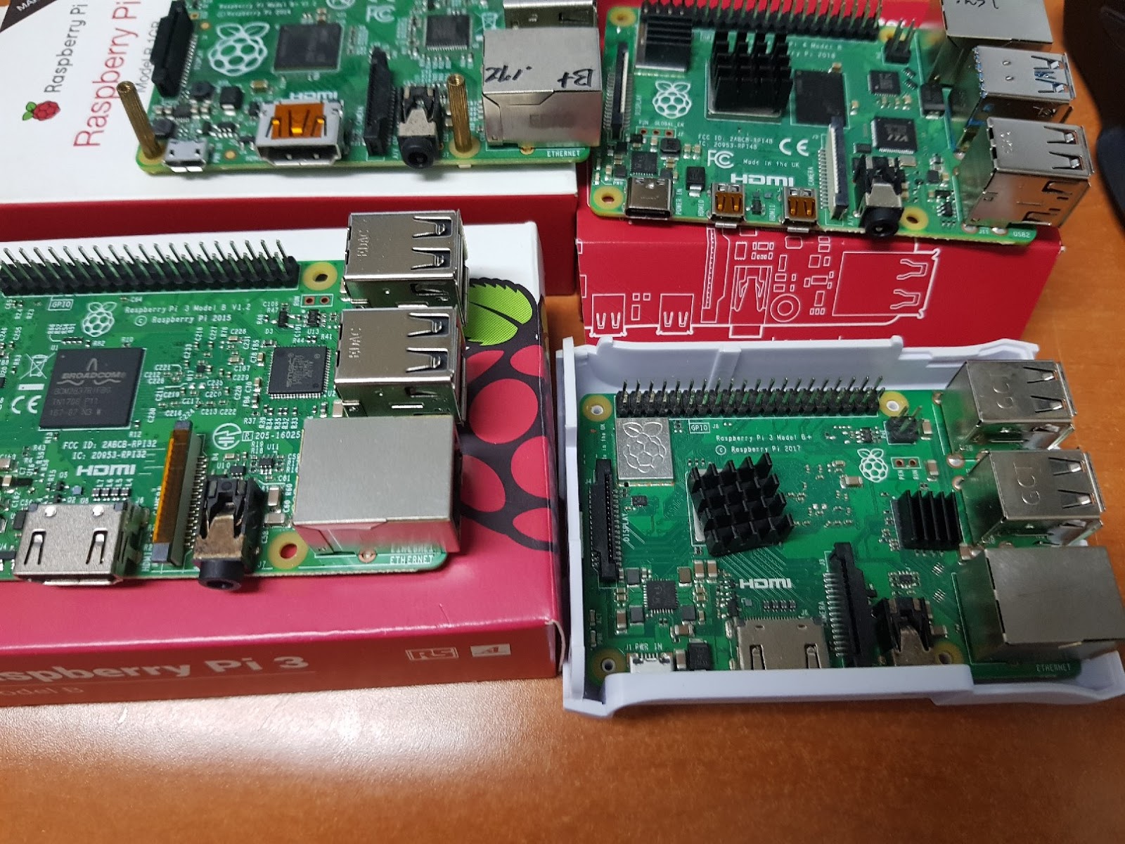
The figure below is a collection of RPI V1 to V4.
It is RPI V1
The board on the right in the photo below is a recent RPI V4.
Already, amateur radios are using a variety of Raspberry Pi boards. I am trying to make something new.
For example, network radios for amateur radio, Devices using Wsjt-x
I experimented with cheap USB sound cards for the new project. All are USB sound cards under $4.
The sound quality was all poor. However, the RPI's fast CPU will enable DSP functionality.
Below is a $2 USB sound card with a cable attached to it. All are compatible with RPI.
Below, I thought it was possible to input a 2CH microphone with a $4 USB sound card. However, it was only 1CH microphone input.
The first project using RPI is a network(DMR) transceiver for DV Switch (or Dv Link).
With an RPI and 3.5 LCD and a USB sound card, it's easy.
You can use DMR more conveniently. (Without DMR radio)