Is port extension or e-delay a universal solution?
Several recent articles examined the use of s11 port extension or e-delay in some scenarios that might have surprised.
Recall that s11 port extension adjusts the measured phase of s11 based on the e-delay value converted to an equivalent phase at the measurement frequency.
It is:
- an exact correction for any length of lossless line of Z0=50+j0Ω transmission line;
- an approximate correction for a very low loss length of approximately 50Ω transmission line; and
- an approximate correction for some specific scenarios such as those discussed at Some useful equivalences of very short very mismatched transmission lines – a practical demonstration.
Of course 1. does not exist in the real world, but 2. can give measurement results of acceptable accuracy if used within bounds. Both departures mentioned in 2. occur in the real world, non-zero loss and departure from Z0=50+j0Ω. Provided these departures are small, port extension may give acceptable results.
Let’s analyse some example measurements based on a 10m length of ordinary RG58A/U from 1-11MHz.

Above, measurement of the first series resonance with SC termination.
Note that the curve is a spiral inwards from the outer circle, the line is not lossless.
A requirement for e-delay to work well is that phase of s11 is proportional to frequency. This plot wraps, but apart from that, the plot looks approximately linear… however scale prevents detailed analysis.

Above, measurement of the first series resonance with OC termination.
Note that the curve is a spiral inwards from the outer circle, the line is not lossless.
Again the plot wraps, but apart from that, the plot looks approximately linear… however scale prevents detailed analysis.
Let’s find a value for e-delay at 1MHz and analyse the result.

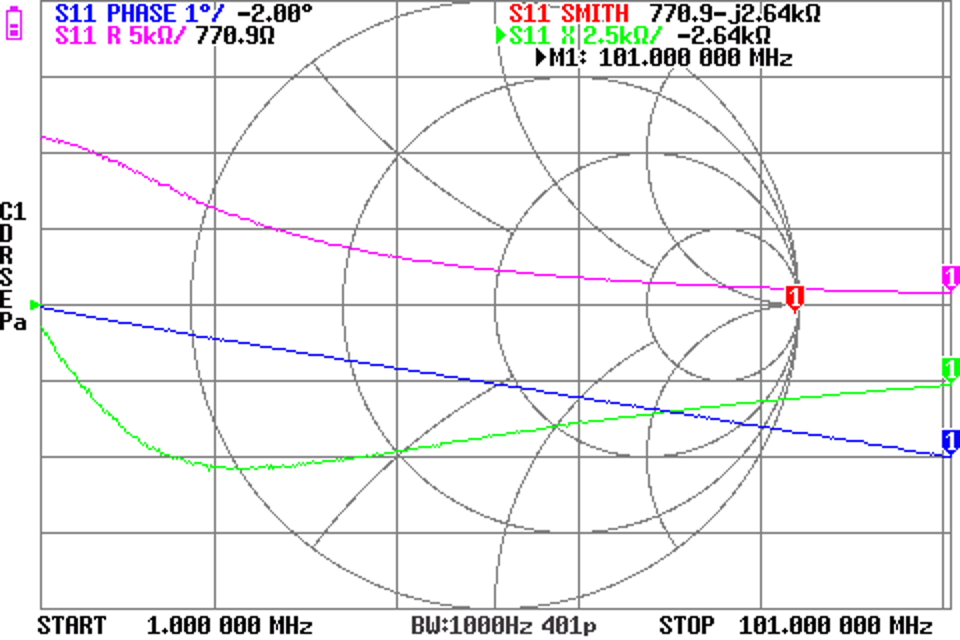
Above is adjustment of e-delay to 115ns for approximately s11 phase 180° at 1MHz with SC termination.
The phase is correct at 1MHz, but at higher frequencies, it departs. So, the assumption that this TL has phase delay proportional to frequency is invalid. If you look closely, it is not a perfectly straight line, there is a small oscillation superimposed which is a sign of Z0 error. For these reasons, e-delay correction will have error.

Above is adjustment of e-delay to 100ns for approximately s11 phase 180° at 1MHz with OC termination.
The phase is correct at 1MHz, but at higher frequencies, it departs. So, the assumption that this TL has phase delay proportional to frequency is invalid. If you look closely, it is not a perfectly straight line, there is quite an oscillation superimposed which is a sign of Z0 error. For these reasons, e-delay correction will have error.
Let’s proceed anyway and look at the error. We will connect the 50+j0Ω termination load to the end of the cable and measure with each of the e-delays above.

Above is measurement of a 50+j0Ω termination with e-delay calibrated using 100ns e-delay (calibrated to OC termination). Note that the curve is a small circle, a sign of Z0 error and a hint that actual Z0 is about the centre of the circle plotted. Note though that Z0 is frequency dependent at these frequencies for this cable, so you can’t pin a pin on the chart and say this is Z0.

Above is measurement of a 50+j0Ω termination with e-delay calibrated using 115ns e-delay (calibrated to SC termination). Note that the curve is a small circle, a sign of Z0 error and a hint that actual Z0 is about the centre of the circle plotted. Note though that Z0 is frequency dependent at these frequencies for this cable, so you can’t pin a pin on the chart and say this is Z0.
At 5.75MHz and:
- e-delay from the SC calibration, Z=45.01+1.25Ω; whereas
- e-delay from the OC calibration, Z=45.01-1.26Ω.
For some purposes, that might be sufficient accuracy, for others it might be unacceptable:
- Z0 departure is more significant for lossier cables below about 10MHz; and
- in any event loss of tenths of a dB leads to measurable error.
Conclusions
Port extension or e-delay can provide a convenient means of shifting the reference plane given suitable test fixtures, but it is subject to significant error if the underlying assumption of lossless 50Ω line is breached.