Normal view

There are new articles available, click to refresh the page.
Before yesterdayowenduffy.net

CMRR and transmitting antennas

By: Owen
11 August 2024 at 00:33

Since the widespread takeup of the NanoVNA, a measure of performance proposed by (Skelton 2010) has become very popular.

His measure, Common Mode Rejection Ratio (CMRR), is an adaptation of a measure used in other fields, he states that he thinks the application of it in the context of antenna systems and baluns is novel and that “CMRR should be the key figure of merit”.

Skelton talks of different ways to measure CMRR, but essentially CMRR is a measure of the magnitude of gain (|s21|) from Port 1 to Port 2 in common mode, with the common mode choke (or balun) in series from the inner pin of Port 1 to the inner pin of Port 2.

Note that this is the same connection as used for series through impedance measurement, but calculation of impedance depends on the complex value s21.

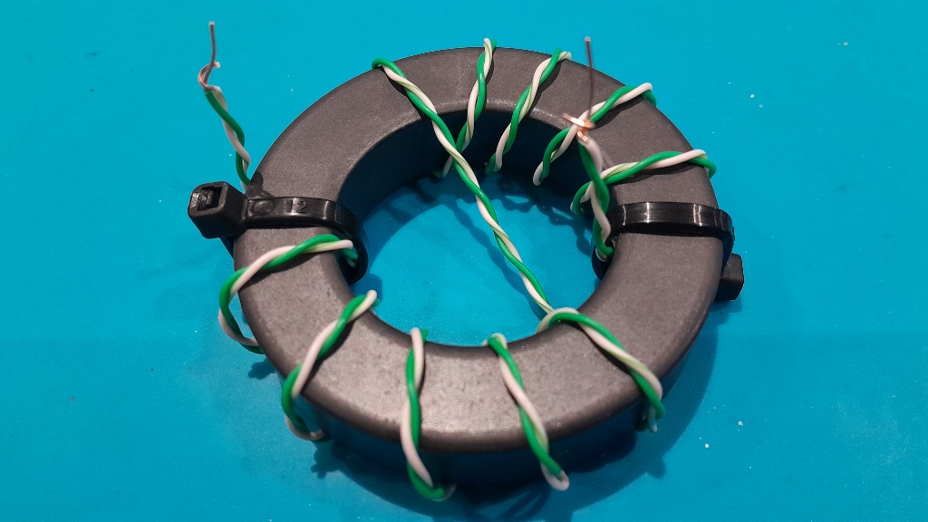
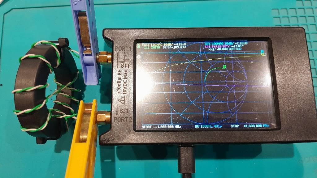
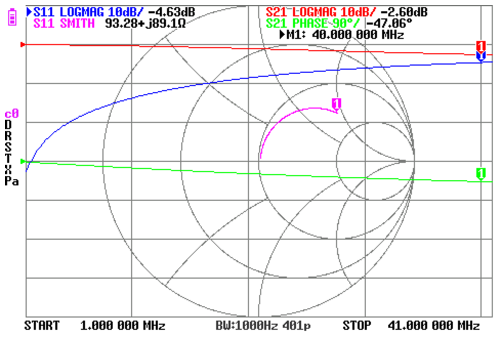
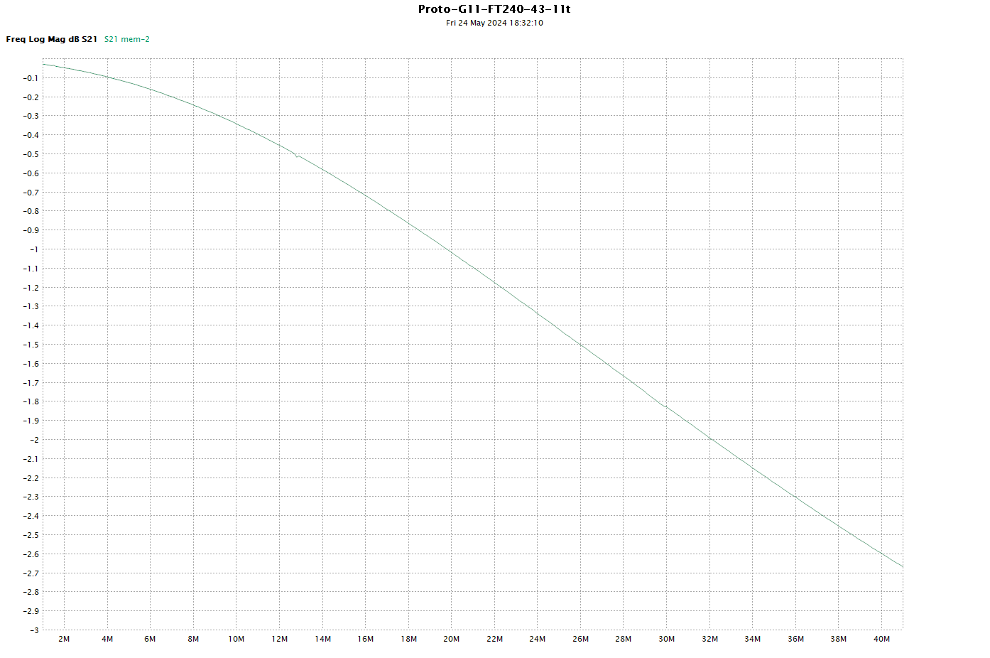
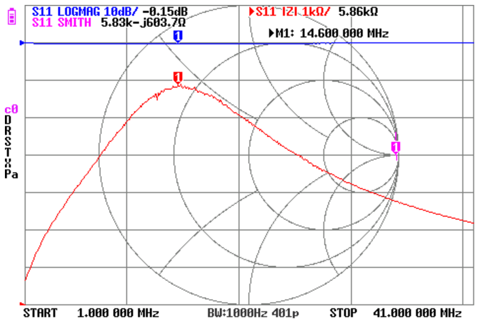
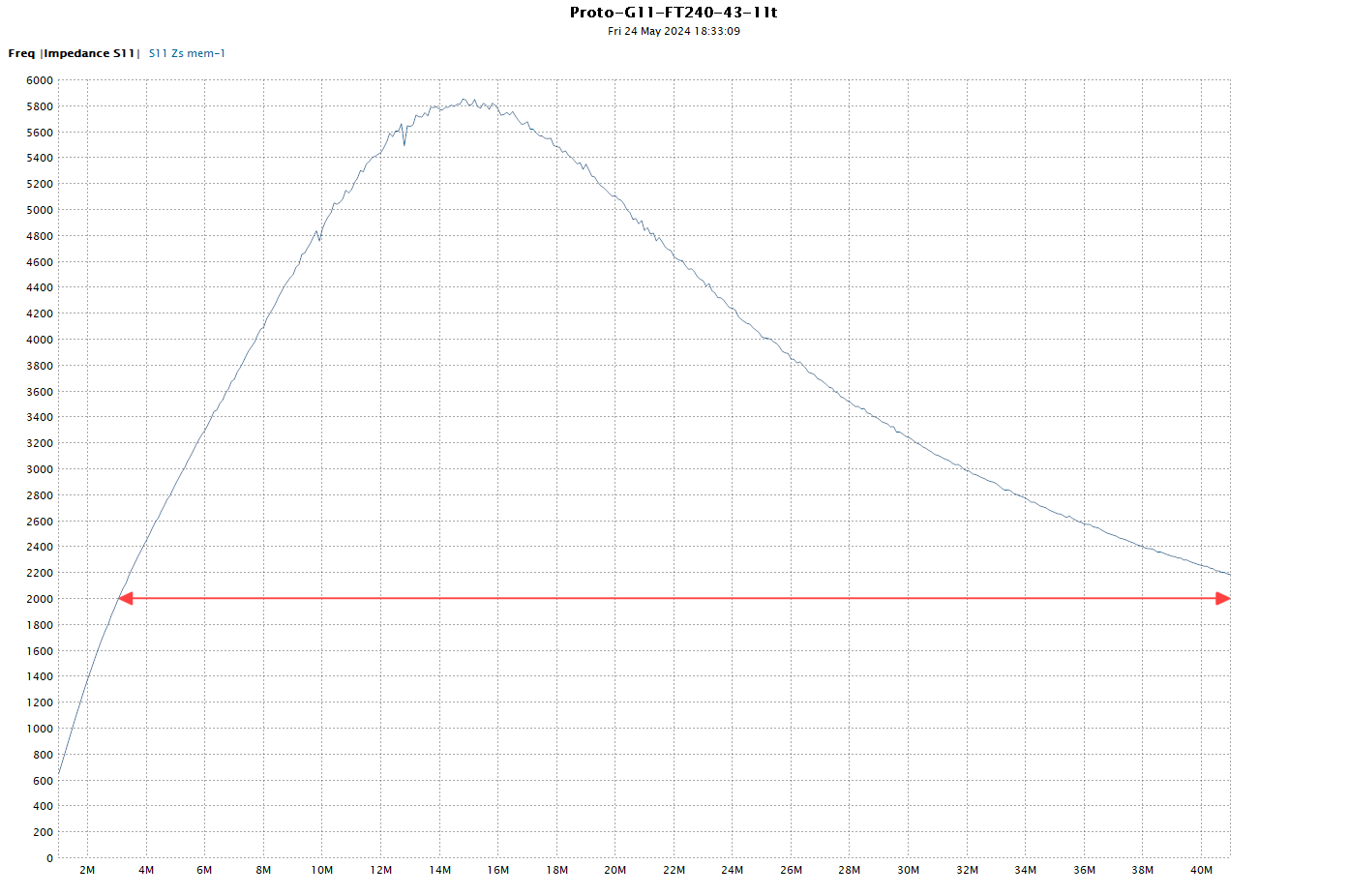
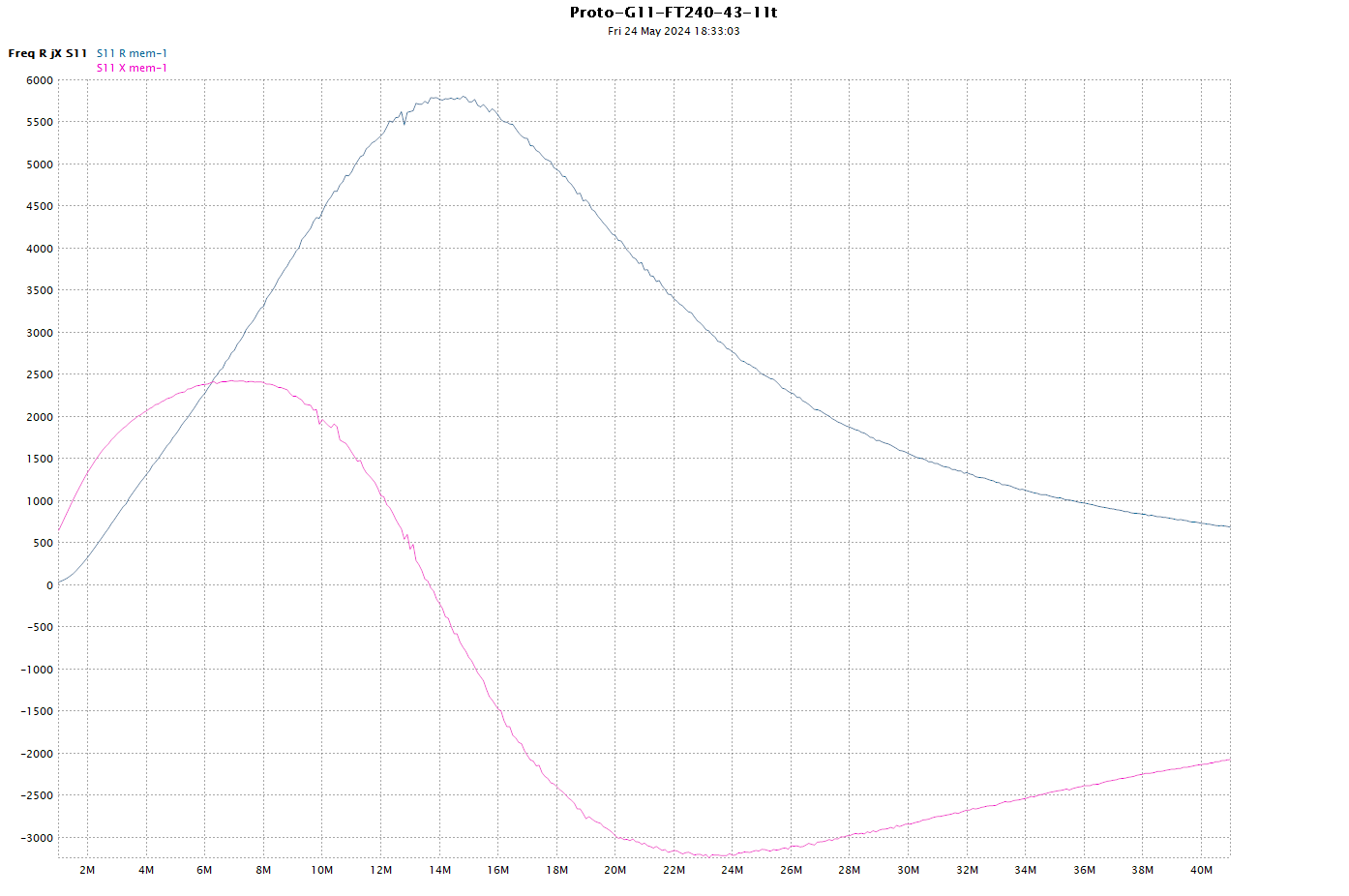
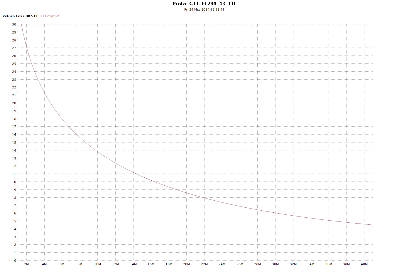
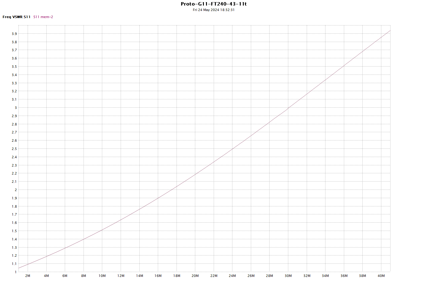
Above is capture of a measurement of a Guanella 1:1 common mode choke or balun. The red curve is |s21|, the blue and green curves are R and X components of the choke impedance Zcm calculated from s21.

Matched vs mismatched DUT

Case 1: impedance matched DUT

In this type of test, the DUT between Port 1 and Port 2 is a good match to both Port 1 and Port 2.

Lots of readers will understand that if they connected a long piece of 50Ω coax between Port 1 and Port 2, and measured |s21|=-6dB, that it is reasonable to say that the cable appears to have an attenuation or loss of 6dB for that length. Further, that the current into Port 2 is exactly half of that out of Port 1… the current has been “attenuated”.

If the DUT is deployed in another matched scenario, you would expect to observe similar behavior, including attenuation.

Case 2: impedance mismatched DUT

In this type of test, the DUT between Port 1 and Port 2 is not a good match to both Port 1 and Port 2.

For example, the matched DUT case does not apply if you made an electrically short connection between ports using a series resistor, the current from Port 1 to Port 2 is approximately uniform. If the DUT is a electrically short inductor, capacitor resistor, or combination with only two terminals, one connected to Port 1 inner and the other connected to Port 2 inner, the same thing applies, the current into Port 2 is approximately equal to the current out of Port 1, the current has NOT been “attenuated”.

If the DUT is deployed in another undefined mismatched scenario, you should not expect to predict behavior based on the simple |s21| measurement.

Interpretation of the |s21| plot above

The widespread interpretation of |s21| for the balun test described above is that it is a plot of the common mode current attenuation property of the balun.

That is deeply flawed, very popular, but deeply flawed. The measurement is of the type discussed under Case 2 above, and the two terminal DUT does not possess some intrinsic attenuation property independent of its measurement context.

Interpretation of the plotted series through R,X derived from the complex s21 measurement, so-called series through s21 impedance measurement

It is popularly held that it is valid to measure common mode impedance (Zcm) by this technique, superior even by many authors… but let’s stay with valid for the moment.

The calculation of series through impedance from s21 depends on an assumption that the current into Port 2 is exactly equal to that out of Port 1, there must NOT be any reduction or attenuation of current in the test setup, otherwise the results are invalid.

Properly executed, this IS a valid technique for measuring Zcm… and one of the necessary conditions is that there is no reduction in current from Port 1 to Port 2.

So, you cannot accept the common technique for series through s21 impedance measurement and at the same time entertain the concept of a matched attenuator DUT.

Bringing it all together

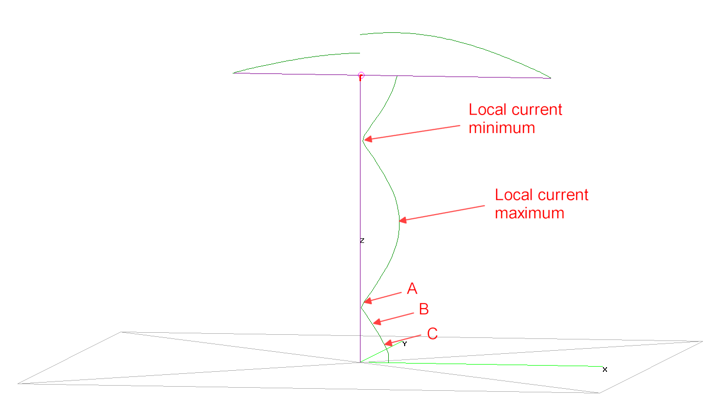
Let’s explore the system response using three terminal measurement of the antenna system impedance and the balun measured above.

Working a common mode scenario – VK2OMD – voltage balun solution reports a three terminal impedance measurement of an antenna system at 3.6MHz.

This following presents calculation of some interesting balun / drive scenarios based on those measurements and Zcm of the balun reported above, and repeated here for convenience.

Above, an identical balun was measured to find |s21| of the balun in common mode. Also shown is the s21 series through measurement of Zcm.

The oft touted CMRR is + or – |s21|, depending on the author and their self defining measurement. Let’s take Skelton’s definition and call CMRR for this balun 29.4dB.

Let’s list the key configuration parameters:

  • frequency=3.6MHz;
  • drive voltages V1 and V2 are not perfectly balanced as detailed in the table below;
  • other key parameters are listed in the table.

Above is a table showing for each configuration, the magnitude of the total common mode current |2Ic|, |2Ic| relative to the No balun baseline configuration, differential current |Id|, and |2Ic/Id| as a percentage.

Note that these currents are potentially standing waves, and they are measured at the antenna entrance panel, about 11 m of two wire feed line from the dipole feed point.

You might ask in respect of the total common mode current:

  1. is the no balun result surprising?
  2. is the current balun performance surprising?
  3. is the voltage balun performance surprising?
  4. does the measured CMRR of 29.2dB imply the reduction in common mode current due to the current balun of 24.3dB?
  5. what does the measured CMRR infer?
  6. can the CMRR be used in an NEC model of the system scenario?
  7. can Zcm be used in an NEC model of the system scenario?

References

  • Agilent. Feb 2009. Impedance Measurement 5989-9887EN.
  • Agilent. Jul 2001. Advanced impedance measurement capability of the RF I-V method compared to the network analysis method 5988-0728EN.
  • Anaren. May 2005. Measurement Techniques for Baluns.
  • Skelton, R. Nov 2010. Measuring HF balun performance in QEX Nov 2010.
Last update: 11th August, 2024, 10:33 AM

nanoVNA-H – Deepelec test jig #2

By: Owen
17 July 2024 at 22:59

I have found you can never have enough of these things. It is very convenient to leave some measurement projects set up while work continues on some parallel projects.

Above is the kit as supplied (~$8 on Aliexpress). Note that it does not contain any male turned pin header… more on that later.

I was critical of Alixpress four years ago when I purchased the last one, but things have improved greatly in that time, to the point they are often faster delivery that eBay’s “Australian stock” sellers.

Carefully break off 7 x 7 way pieces of the turned pin female header and ‘dry’ fit them to the board, Now get two more pieces of header that are at least 7 way, and plug them at right angles to the ones already placed to set the spacing. Now solder them to the board (hint: liquid flux makes this job easier.) The ‘donuts’ are quite small, use a tip that gives contact to the donut so that heat is applied to the pin and the ‘tube’ for a good solder joint.

Test the coax connectors on a good male connector to be sure they are not defective… quality of these is poor. I tighten them to 0.8Nm to seat and form the female connector. If the threads bind, chuck them now rather than after you have soldered them in place.

I installed only the mid connectors on this board, I have another which has all the connectors and I have never used the other four. Carefully position and solder the connectors, again liquid flux helps.

The clear plinth does not come in the kit, it is my addition.

Above, the plinths designed in Freecad were cut out of 3mm clear PVC.

They are cut using a single flute 2mm carbide cutter.

You could easily make them with hand tools and a drill. M2.5×6 nylon screws are used to attach the plinth to the hex spacers (supplied), giving the assembly four non-scratch feet.

Now the kit is incomplete. You are going to need some parts you see above built on male turned pin header strip. The kit does contain some 49.9Ω resistors you can use for a LOAD, you will also need an OPEN (centre left) and a SHORT (lower right). Others are for connecting the sections of the test board and THROUGH calibration.

The SMA connector at left is another test fixture which uses the same calibration parts. It can be used directly on the NanoVNA or at the end of a convenient length of cable. I originally made it to use on a Rigexpert AA600, either on a N(M)-SMA(F) adapter, or a short N(M)-SMA(F) cable.

It is bit hard to see the connections on the board when it is populated, so I have made the graphic above, printed it and laminated it for handy reference.

Note that the connections are a little different to the SDR-Kits jig (that they probably copied), in particular C2, C6, E2 and E6 are each not connected to anything.

I have some custom made 300mm long RG400 cables that I use with these, labelled for calibration purposes. IIRC they cost about $30 per pair from RFSupplier.com.


Last update: 18th July, 2024, 9:20 AM

NE6F’s common mode current tester – Part 2

By: Owen
30 May 2024 at 23:35

NE6F’s common mode current tester – Part 1 ended with the following:

Common mode current adjacent to a small choke

Consider a straight section of coaxial feedline not close to other materials, and with a small common mode choke inserted in the feedline. A “small” choke means one that is a very tiny fraction of a wavelength, say λ/100, from connector to connector.

Q1: Ask yourself that if say 1A of common mode current flows into one connector, what is the common mode current at the other connector?

Q2:What is your answer if you were told the balun was specified to have a CMRR of 20dB?

The answer to Q2 is relatively easy, CMRR is not a meaningful statistic for a common mode choke deployed in a typical antenna system, it would not change the answer to Q1.

The answer to Q1 needs a longer explanation… let’s do it!

Common mode current distribution is almost always a standing wave.

Above is a plot of current distribution of an example dipole antenna system with coax feed. The dipole is slightly off centre fed to drive a significant common mode current on the vertical coax feed  which is grounded at the lower end.

Note the standing wave on the vertical section, it has maxima and minima (if it is long enough), and these are unrelated to possible standing waves inside the coax, ie in differential mode.

Note that if we took spot measurements of the magnitude of common mode current |Icm| at points A, B and C we would get different results.

Broadly, Icm changes relatively slowly over a small electrical distance (say λ/100), except near deep minima if they exist.

Above is the same model with a common mode choke inserted near ground. Note that it has changed the magnitude and distribution of Icm, and more importantly, note that |Icm| at both ends of the choke are very similar, and in fact slightly lower on the antenna side of the choke.

If you make spot measurements either side of an electrically short (say length<λ/100), you will not usually find a large difference… except in the region of a current minimum.

The common notion that |Icm| is much lower on the tx / ground side of the choke is deeply flawed, and even worse is to think that CMRR can be used to calculate the reduction.

NE6F’s video of measurement of his balun’s effectiveness.

N6EF demonstrates measurement with his dual probe meter asserting that “this choke is doing a pretty good job,” but is the measurement a valid basis for that assertion?

Above is a capture from the video with my added notations of four currents, I1-4.

Having set his instrument to read 100% of scale on the Port A probe, he switches to display the Port B probe.

Above. a stunning drop, it is reading perhaps <1% of scale on Port B. Some might infer that proves CMRR>40dB.

Let’s look at that test setup again.

Above is a capture from the video with my added notations of four currents, I1-4.

NE6F demonstrates that I4 is less than 1% of I1 (though the meter response may not be linear at low readings).

Now look at the conductive bulkhead and the bulkhead adapter which connects the coax shield to the bulkhead. At this point a circuit node with three conductors is formed and currents annotated:

  • I1: shield from the antenna side;
  • I2: bulkhead conductor; and
  • I3: shield to the choke.

The measurement made ignores the presence of current path I2, and so all conclusions are invalid.

With the information given earlier, you might well think that it is likely that I3 is approximately the same as I4 (measured at <1% of I1), and that I2 is probably almost the same as I1, ie that this shunts, diverts common mode current on the antenna feed line to ground. That might be an effective measure in preventing ingress to the equipment cluster, but it does not reduce Icm on the main feedline or the undesirable effects of that.

Of course that is just supposition… but it should drive measurement of |I3| to better infer |I2|.

Homework

Make or buy an effective common mode current meter, and make some measurements adjacent to a common mode choke to test your understanding of what it does or does not do.

Last update: 1st June, 2024, 2:54 PM

NE6F’s common mode current tester – Part 1

By: Owen
25 May 2024 at 21:44

A correspondent asked my thoughts on a Youtube video featuring…

NE6F’s common mode current tester

Above is the schematic of NE6F’s common mode current tester.

The concept is that current probes A and B are placed either side of a current mode choke, and by calibrating and switching between them, a relative reading of current on one side compared to the other may be found.

Note that the two transformers are intended to be current transformers, they have a ratio of 1:10 turns so the \(Is=\frac{I_p}{n^2}=\frac{I_p}{100}\) … provided there is a low impedance load (called a burden) connected to the secondary.

If the burden was say 100Ω, then the current transformer inserts an impedance of approximately 100/10^2=1Ω in the primary circuit. If a current sensing element does not have a very low impedance, it is likely to disturb the thing being measured.

A general rule about current transformers is that if there is no burden on a current transformer:

  • excessive / dangerous voltage may be developed by the secondary winding;
  • a high impedance may be inserted in series with the primary line.

So, this is a current transformer with a burden of megohms, a deeply flawed design, but that problem is easily fixed by connecting a resistance of say 100Ω across each secondary winding.

Common mode current adjacent to a small choke

Consider a straight section of coaxial feedline not close to other materials, and with a small common mode choke inserted in the feedline. A “small” choke means one that is a very tiny fraction of a wavelength, say λ/100, from connector to connector.

Ask yourself that if say 1A of common mode current flows into one connector, what is the common mode current at the other connector?

What is your answer if you were told the balun was specified to have a CMRR of 20dB?

Take your time… a follow up will be posted in a day or three.

Last update: 26th May, 2024, 8:31 AM

Baluns: you can learn by doing!

By: Owen
25 May 2024 at 05:23

This article presents a simple way to make measurements of a prototype Guanella 1:1 current balun, measurements that can guide refinement of a design.

The usual purpose of these transmitting Guanella 1:1 current baluns is to reduce common mode feed line current. Not surprisingly, the best measure of a device’s effectiveness is direct measurement of common mode current (it is not all that difficult), but surprisingly, it is rarely measured.

Above is the prototype transformer being a Fair-rite 5943003801 (FT240-43) wound with 11t of solid core twisted pair stripped from a CAT5 solid core LAN cable and wound in Reisert cross over style. Note that Amidon #43 (National Magnetics Groups H material) is significantly different to Fair-rite #43.

There is no need to wind a prototype using expensive materials, the measurements made with the above prototype are very useful in guiding development without wasting expensive materials. Further, the measured results are very close to the behavior of the ‘raw’ balun.

s21, s11 measurement of through transmission


Above is the configuration for the through test, the clothes pegs are used to clamp one conductor to the outside of the SMA jacks, the inner wire is poked into the inner pin, the VNA is sitting on a cardboard box, the whole thing is on a wooden table. An alternative to the clothes pegs are small zip ties.

Above is a screenshot from the NanoVNA of the through measurement. The relevant traces are s11 Logmag, S11 Smith, and S21 Logmag.

Above is an expanded graph of |s21|. At first glance, you might be horrified by the value of -1.8dB @ 30MHz. Many would assert that this shows a loss of 1.8dB… but more correctly it is InsertionLoss of 1.8dB and conversion of RF energy to heat is likely to be less.

See Measurement of various loss quantities with a VNA for discussion of Loss terms.

Above is a graph disaggregating InsertionLoss into (Transmission) Loss and MismatchLoss. Thicker conductors will have less Loss, and would be used in practical baluns.

Above is a graph showing InsertionVSWR wrt 50Ω and ReturnLoss wrt 50Ω.

The significant mismatch is due to the fact that the balun introduces about 800mm of transmission line with Zo around 100Ω.

If you want low InsertionVSWR wrt some reference Zo, then the transmission line (the twisted pair or coax) needs to be that same Zo.

Is the InsertionVSWR and associated impedance transformation a problem? Well if you are using an ATU, it should not matter, and imperfection is dealt with by the ATU.

s11 reflection measurement of Zcm

Above, the DUT was reconfigured for Zcm measurement by twisting the white wire around the green wire at each end to bond them, leaving a short straight section of the green wire for connection. One end is inserted into Port 1 jack inner, the other was clamped to the male threads of Port 2, ie grounded.

Note: my NanoVNA-H4 has been modified by addition of a short direct wire between the ground side of Port 1 and Port 2 jacks inside the case (see above).

(If wound with coax, Zcm measurements are made between shield ends, ignore the inner conductor.)

Above is a screenshot of the Zcm measurement, |Zcm| peaks at about 14.6MHz.

Above is a plot of |Zcm| taken from the .s1p file saved during measurement. |Zcm| > 2000Ω from 3MHz to more than 40 MHz.

Above is a plot of the R and X components of Zcm taken from the .s1p file saved during measurement.

Above is a plot of the ReturnLoss taken from the .s1p file saved during measurement.

Above is a plot of the InsertionVSWR taken from the .s1p file saved during measurement.

Conclusions

Good / valid measurements of a prototype Guanella 1:1 balun can easily be made with a NanoVNA using low cost materials in capable hands.

Keep in mind that you are measuring a sample of one or a small number and that ferrite has a wide tolerance specification, and is temperature sensitive.

Experimenting with measurement setups and prototypes is the beginning of understanding of these things, more so that soaking up the utterings of armchair experts.

Go build and measure some prototypes, try different cores, different turns, different winding layouts, twisted / untwisted / coax etc.

Downloads

Proto-G11-FT240-43-11t.7z

Last update: 31st May, 2024, 5:28 AM
❌
❌