❌

Normal view

There are new articles available, click to refresh the page.
Before yesterdayowenduffy.net

Conversion of NOELEC style balun board to 1:1 – through measurement

By: Owen
3 May 2024 at 09:52

Conversion of NOELEC style balun board to 1:1 left readers with a challenge to measure the through performance of the modified balun board.

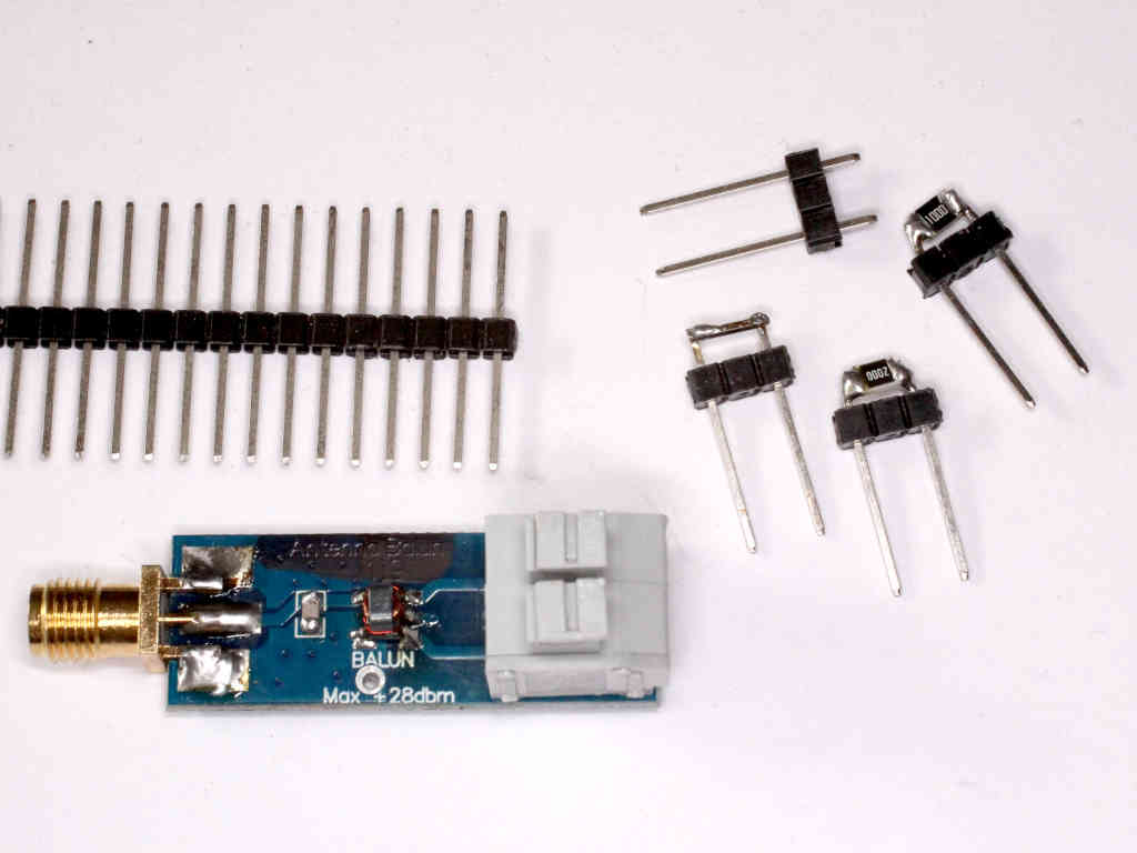
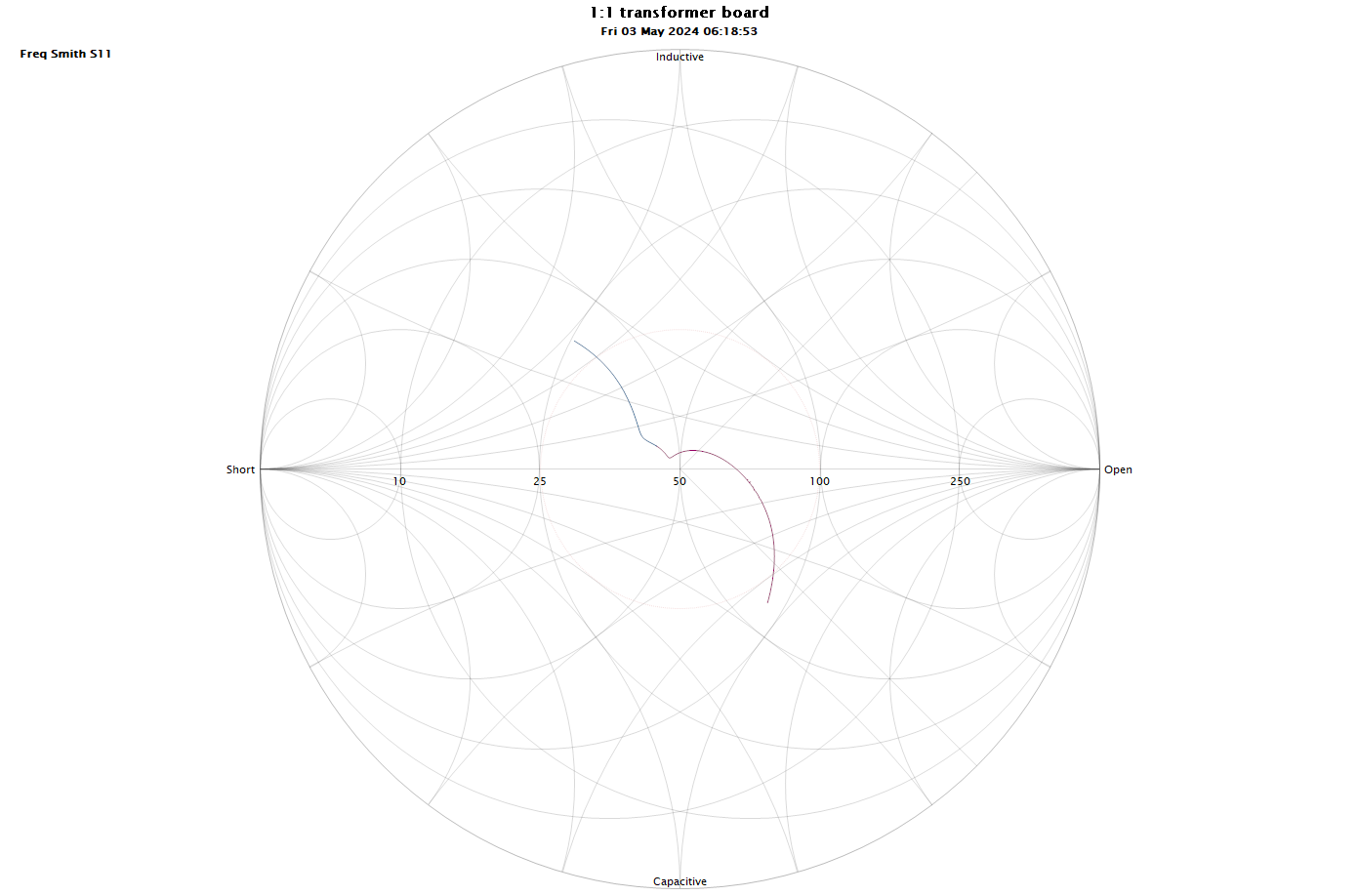
The link grounding the centre tap was cut for this test to float the secondary so that one side could be grounded. This will give almost identical response to the case where the centre was grounded.

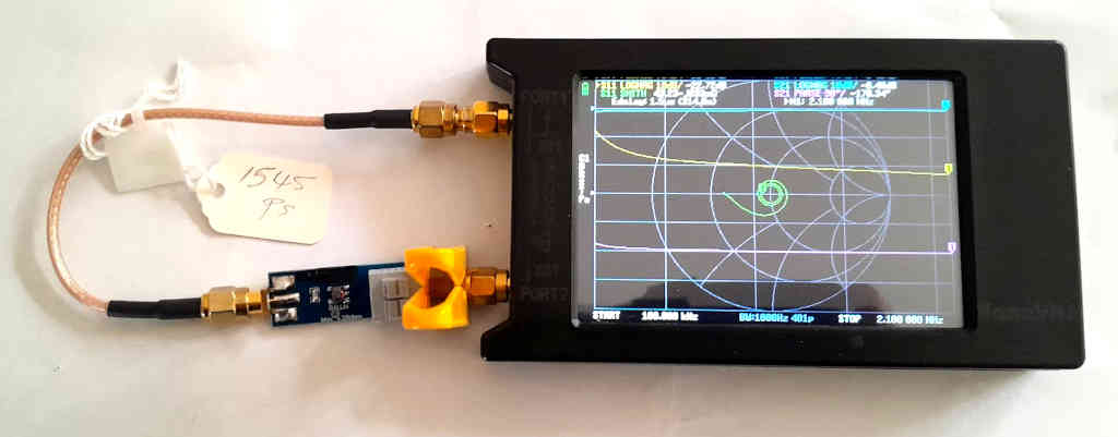
Above is the test configuration, the yellow thing is a top view of a modified plastic clothes peg which is used to clamp one of the wires from the transformer to the SMA threads.

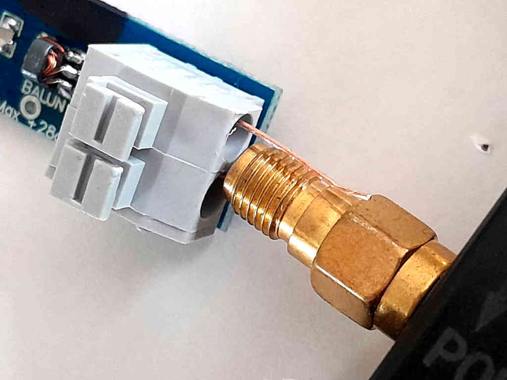
Above is a close up view of the connection without the clothes peg in place, there would not be as much as 3mm of conductor between the grey block and the SMA connector. The wire is 0.5mm diameter single core copper stripped from LAN cable.

Test jigs do not need to be expensive to be effective.

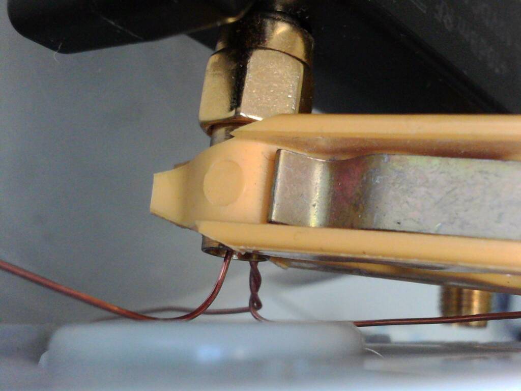
Above, a view of the modified clothes peg from another article.

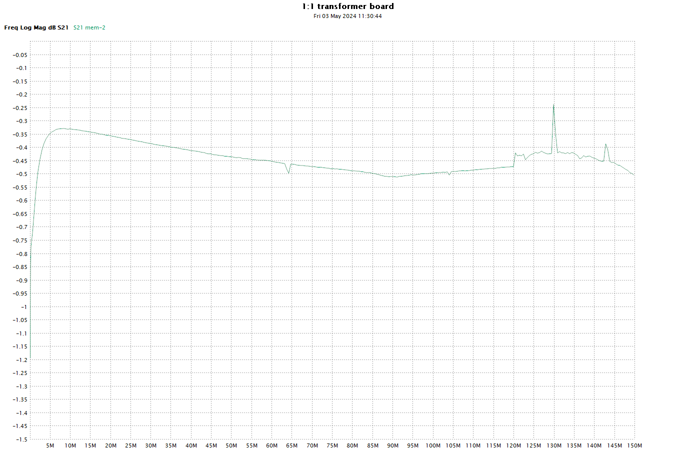
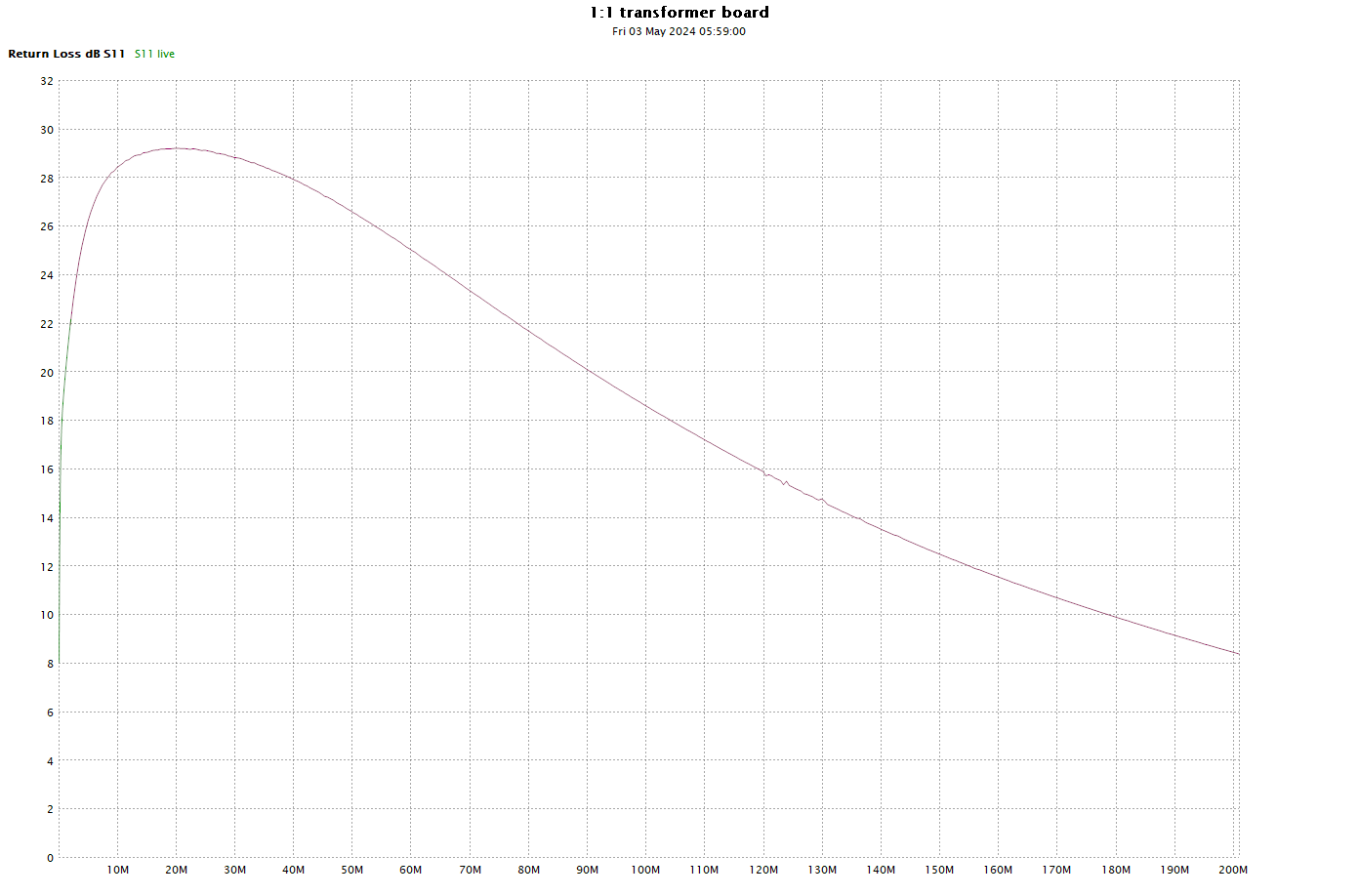
Above is a plot of |s21| to 150MHz. The compensation causes a self resonance at about 180MHz, so whilst improving its InsertionVSWR at lower frequencies, it limits its useful range to about 150MHz.

This plot would commonly be labelled a β€œloss” plot by hammy Sammy… you know, the guy who says the attenuation or loss in my coax is -2dB/100β€².

So, to be clear, it is as labelled the magnitude of s21 expressed in dB and that is equivalent to InsertionLoss. See Measurement of various loss quantities with a VNA for further explanation.

So what is really interesting is to drill down on InsertionLoss.

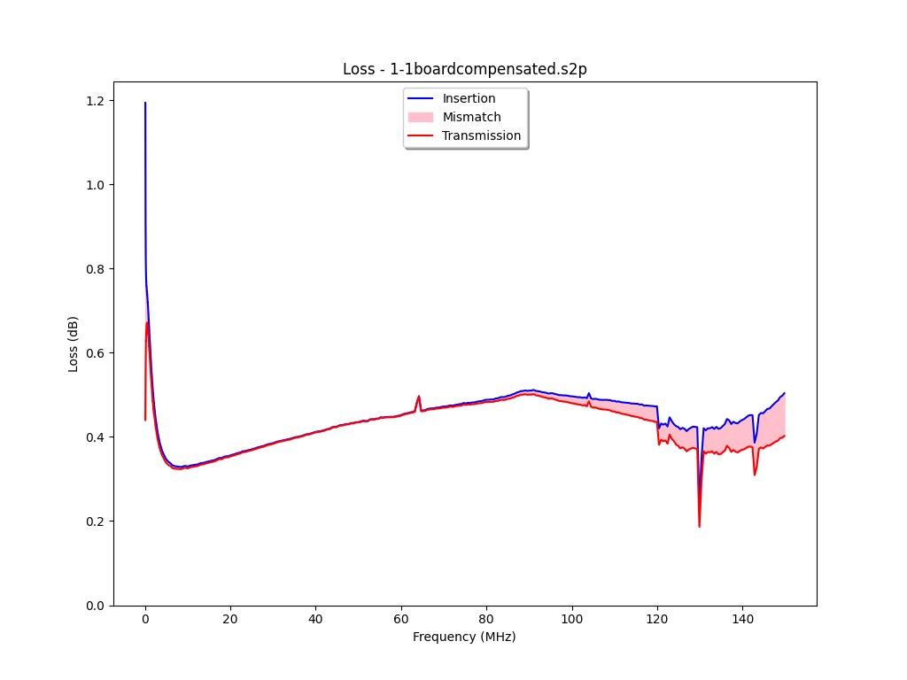
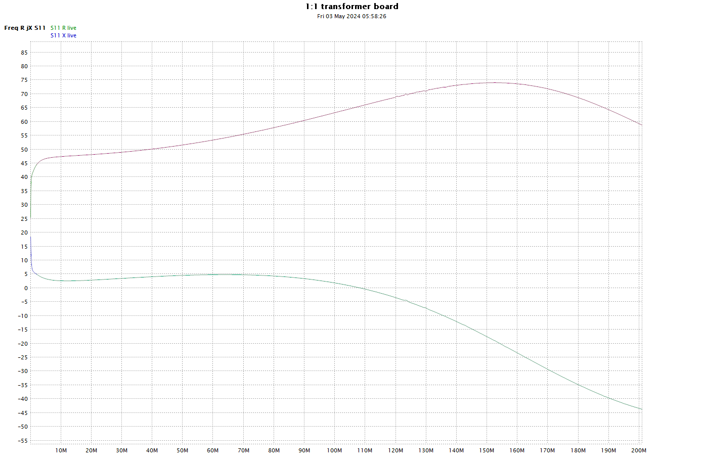
Above is a plot of InsertionLoss and its components (Transmission) Loss and MismatchLoss.

(Transmission) Loss is due mainly to core loss and to a lesser extent some wire loss, and it results in conversion of electrical energy to heat.

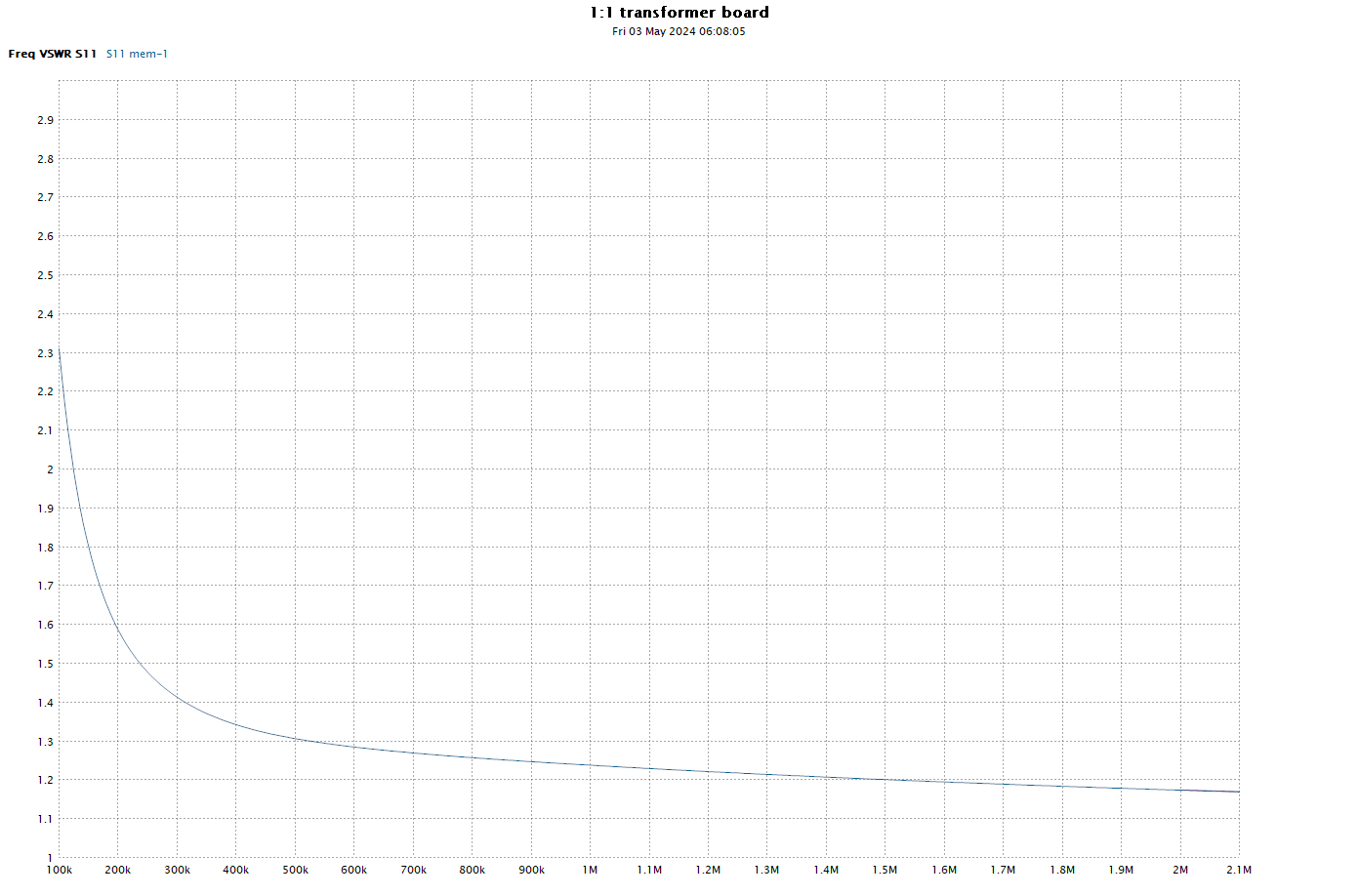
Note that MismatchLoss is very low mid-band, and becomes greater at the lowest frequencies and at the high end. The low end is degraded by high magnetising admittance (too few turns for the frequency, core type). Again, compensation whilst improving the mid band does so at the expense of degrading high end performance. Nevertheless, the module is quite good for many purposes from 400kHz to 150MHz.

Last update: 6th May, 2024, 6:42 AM

Conversion of NOELEC style balun board to 1:1

By: Owen
1 May 2024 at 23:00

This article describes a small 1:1 balun for use in measuring field strength using a TinySA Ultra and a small loop antenna.

The balun is also useful for measurements using the NanoVNA (or any VNA), eg for measuring two wire transmission line parameters.

Materials

Some β€œTC1-1T RF Balun Transformer 0.4-500MHz 1:1CT” transformers were purchased on Aliexpress, 5 for $7. The part number is a Mini-circuits part, but these are likely to be clones. The balun boards also came from Aliexpress, about $4 each. Also needed are compensation caps of 10pF (0805).

Conversion

The boards come with a nominal 1:9 transformer and in my experience a capacitor (though I think the NOELEC board may use a TVS). In any event, it should be removed and the transformer removed. Fit the new transformer and solder a short circuit across the cap pads.

High end compensation

See High end VSWR compensation in a ferrite cored RF transformer for an explanation of compensation.

Connect the board to VNA Port 1 and sweep it to 200MHz, adjusting s11 e-delay so that the trace is a dot at the left of the Smith chart X=0 line. This adjusts the reference plane approximately to the position of the capacitor. Write down the e-delay value for later.

Above is the modified transformer and some calibration parts loads. There are two loads, 200Ξ© 1% and the other has 2Γ—100Ξ© 1% in parallel to give 50Ξ© 1%. The calibration parts are made on ordinary long header pin strips, break three off and pull the middle one out with pliers. Slide the pins to a suitable projection and cut off the other end to uniform length then solder the resistors or shorts to them. This calibration effectively sets the Port 1 coupler Directivity to 46dB (which is quite good).

Measurement

So now, remove the short circuit on the cap pads and fit an accurate 50Ξ© load to the output terminals (such as the one pictured) and sweep 1-200MHz saving the .s1p file.

Open Simsmith and create a new model specifying the .s1p file for element L. Set the sweep to use L.FILE and you should get a L SWR trace like the magenta one above.

Now insert a compensation capacitor (C1 above) and set it to 10pF. Display G SWR and it should be like the blue trace above. Adjust C1 for best compensation to find your optimal compensation capacitor.

Now fit the capacitor, and sweep the balun again to confirm that it now has a response like the blue trace above.

Above is a sweep from 0.1-2.1MHz, the transformer should be usable down to 400kHz.

Above is a sweep from 1-201MHz. The limit of its useful range is determined by the application. It has quite good InsertionVSWR up to 30MHz, and good InsertionVSWR to about 150MHz.

More detail

Adjust the s11 e-delay to 250ps less than the figure you wrote down earlier, this moves the reference plane to approximately the far of the SMA connector so that R and X values are meaningful.

Above is the InsertionVSWR plot from 0.1-201MHz displayed by overlaying the low frequency and high frequency sweeps in NanoVNA-App.

Above is a ReturnLoss view of the same data.

Above is R,X of the same data. Note the effect of compensation is to turn X downwards as the frequency increases.

Above is the Smith chart view.

Grounded centre tap

There is a jumper on the back of the board which grounds the secondary centre tap. You may want to cut it for some applications. My own experience in measuring samples of two wire line is that it is better grounded. If you cut it with a fine cut, the connection can easily be remade with a dot of solder.

Other transformers

Other transformers can be used, though compensation depends on the transformer leakage reactance to a large degree.

Off the shelf 1:4 transformers are readily available, and work well though with a larger compensation cap.

You could wind your own transformer on a very small ferrite core. The smaller the core, the easier to obtain good broadband performance.

An exercise for the reader

Measure your own including s21. To measure s21, cut the ground link under the board for the centre tap so that the secondary is isolated and you can connect it to Port 2 with very short wires. It is not exactly the same, but it is a very good approximation.

Last update: 11th May, 2024, 4:29 AM
❌
❌