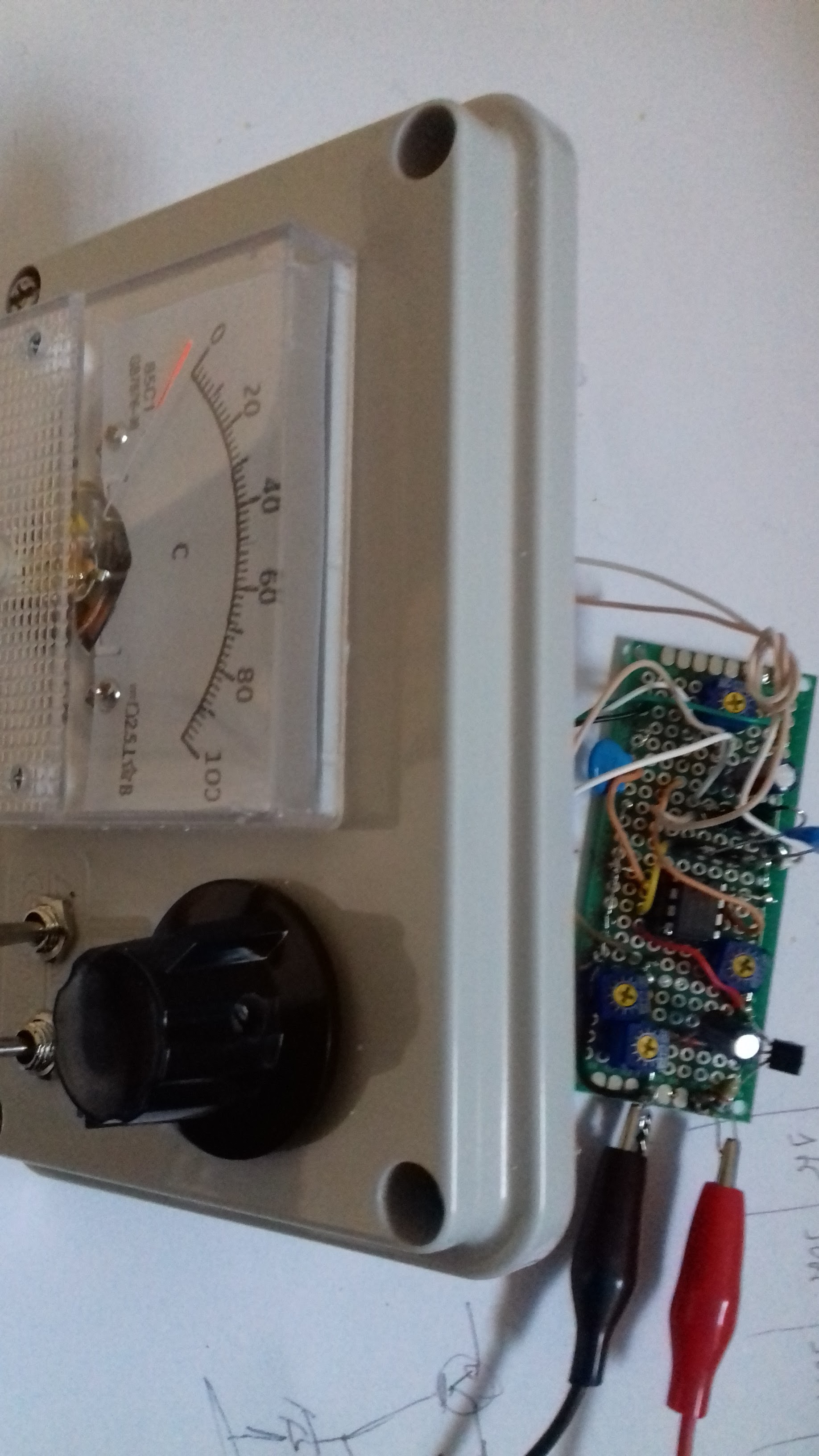
Simple ESR meter
25 June 2023 at 21:24
Almost a copy from here.

Diagram from the original site:
Inside:

and during testing:

Works nice, handy for testing old caps.
Have a nice day!
![]()

Almost a copy from here.
Diagram from the original site:
Inside:
Works nice, handy for testing old caps.
Have a nice day!
![]()
As title says; a simple capacitance meter.
One youtube video by VK3YE was enough to get me started building, after all, the meter that I was using before was not behaving correctly (latter found the problem).
The outcome was this:


To calibrate I used a 68pF and 27pF capacitor, the idea was not to have highest precision possible only to be in a position of having certain about unmarked capacitors.
Some description/schematic from here and here:

I used different Ge diodes and the 10K pot was changed for 2 of 5K in series to give better adjustment range. The Zener was changed to 6.8v.
Ranges like this:
E: 100pF
D: 1nF
C: 10nF
B: 100nF
A: 1uF
Have a nice day!
![]()
Had this build for some time, now it's time to show.
I was doing some experiments on the 10Ghz band and wanted a way of looking at the signals. Because the spectrum analyser I have only good to 1.5Ghz had to find a cheap way of doing it to get this:
The diagram explanation: a dbm mixer (Watkins-Johnson M80LCA) with a local oscillator based on a FVC99 10Ghz oscillator module (cheapest VCO I could find for 10Ghz). Some preamps on the input and output using 2Ghz preamp modules and replacing the MMIC amplifiers for the ones like Corvo NLB300 or ERA-1 that are good to 10Ghz.
![]()
The basic design:
There is no stability control on the FVC99 oscillator, still working on a PLL system (maybe one of these days) but in my case I have two select positions, one: VCO is controlled by a single pot (like on the diagram) and the other position controlled by an EIP371 frequency counter (from the Lo Out via directional coupler) that makes the PLL loop. With EIP371 and since the output voltage of the loop is very small the control range seats near 9.5Ghz, there is an option of extending the range like on the EIP manual:
Or with a similar diagram, a multiply by 10 of the PLL voltage out of the EIP371, that would be enough to use the full range of the FVC99.
For now I use 9.5 Ghz if using the EIP371 for more stability and around 10Ghz set by the pot ("Flo" on the panel) if it's just a quick test.
Here the EIP working as external PLL controling the FVC99 so the LO gets more stable.
On the Rigol DSA815 spectrum analyser you can set the input offset to get the display right on the band of interest
Displaying here a 10Ghz signal using the 9.5Ghz Lo frequency
Inside view:
Some other images during prototype development:
Testing during early days of the prototype with a 10Ghz homemade flange to SMA adapter and a pipe cap filter:
Anyhow, not a measuring device but it serves the purpose of checking if you have any signal around the 10Ghz band and for experiments, still very happy with the outcome and sensitivity.
Have a nice day!
![]()


The code on the current version, keep in mind might still have some bugs, reach me for latest version if there is one: If blogger breaks formatting ask me a copy by email.
ADF4351 signal generator
CT2GQV 2020
v1.4
Based on code from: ADF4351 example program https://github.com/dfannin/adf4351
VFO with 100Khz steps starting from a predifined frquency (UL frequencia) using 2 buttons for up and down.
Display on 16x2 I2C LCD of the frequency set and the third harmonic value
Also serial output of the main frequency set.
Possibility to sweep for filter testing.
*/
#include <Arduino.h>
#include "adf4351.h"
#include <LiquidCrystal_I2C.h>
#define SWVERSION "1.4" // 2021-09-11
#define PIN_SS 9 ///< SPI slave select pin, default value
ADF4351 vfo(PIN_SS, SPI_MODE0, 1000000UL , MSBFIRST) ;
//unsigned long frequencia = 3333320000UL ; // 3.333.334 (10 Ghz n=3)
unsigned long frequencia = 3496500000UL ; // 3.496.000 (10.489 Ghz n=3)
unsigned long maxfrequencia;
unsigned long minfrequencia;
// unsigned long frequencia = 2000000000UL ; // 2.000.000 (10 Ghz n=5)
// unsigned long frequencia = 414000000UL ; // 414.000 (10.368 Ghz n=25)
// for 442Mhz use the bellow and comment the above
// unsigned long frequencia = 442000000UL ; // 442Mhz or 1.326 Ghz , tird harmonic
// I2C LCD virtual pinout
#define I2C_ADDR 0x27 // I2C Address for my LCD, found with I2C scanner
#define BACKLIGHT_PIN 3
#define En_pin 2
#define Rw_pin 1
#define Rs_pin 0
#define D4_pin 4
#define D5_pin 5
#define D6_pin 6
#define D7_pin 7
LiquidCrystal_I2C lcd(I2C_ADDR, En_pin, Rw_pin, Rs_pin, D4_pin, D5_pin, D6_pin, D7_pin);
// buttons for up/down in frequency, puleed up from 5v with a 10K resistor, analog pin will be short to ground for button press
int button0 = 0; // mode
int button1 = 1; // up
int button2 = 2; // down
int button3 = 3; // select / band / step
int opmode = 0; //
int tempopmode = 0; //
int band = 0;
// Band 0 - 10Ghz (3.3Ghz harmonic) - 10489.550 to 10489.795MHz ->
// Band 1 - 2400.050 frequencia = 2400500000UL
// Band 2 - 1969.5Mhz (-2400 = 431Mhz )
// Band 3 - 2256 (2400-144Mhz) - 2400.050 to 2400.295MHz
// band 4 - 739.55 - LNB out
void setup()
{
Serial.begin(9600) ;
Serial.print("adf4351 VFO CT2GQV "); Serial.println(SWVERSION) ;
pinMode(button0, INPUT); // mode
pinMode(button1, INPUT); // up
pinMode(button2, INPUT); // down
pinMode(button3, INPUT); // band
lcd.begin (16, 2, LCD_5x8DOTS); lcd.setBacklightPin(BACKLIGHT_PIN, POSITIVE); lcd.setBacklight(HIGH); // 20x4 lines display LCD
lcd.home();
lcd.setCursor(0, 0); lcd.print("Signal Generator ");
lcd.setCursor(0, 1); lcd.print("Ver: "); lcd.print(SWVERSION);
Wire.begin() ;
/*!
setup the chip (for a 10 mhz ref freq)
most of these are defaults
*/
vfo.pwrlevel = 3 ; // measured at 3.3Ghz after 1m cable >> "0" = -8 dBm / "1" = -5.8dbm / "2" = -3.3dbm / "3" = -0.4dbm
vfo.RD2refdouble = 0 ; ///< ref doubler off
vfo.RD1Rdiv2 = 0 ; ///< ref divider off
vfo.ClkDiv = 150 ;
vfo.BandSelClock = 80 ;
vfo.RCounter = 1 ; ///< R counter to 1 (no division)
vfo.ChanStep = steps[2] ; ///< set to 10 kHz steps
/*!
sets the reference frequency to 10 Mhz
*/
if ( vfo.setrf(10000000UL) == 0 )
Serial.println("REF.SET: 10 Mhz") ;
else
Serial.println("ERROR: reference freq set error") ;
/*!
initialize the chip
*/
vfo.init() ;
/*!
enable frequency output
*/
vfo.enable() ;
delay(500);
lcd.clear();
if ( vfo.setf(frequencia) == 0 ) {
Serial.print("VFO.SET:") ; Serial.println(vfo.cfreq) ;
lcd.setCursor(0, 0); lcd.print("F :"); lcd.print(frequencia/1000);
lcd.setCursor(0, 1); lcd.print("F(3):"); lcd.print((frequencia/1000)*3);
} else {
Serial.println("ERROR: Set init Frequency") ;
}
vfo.ChanStep = steps[4] ; ///< change to 100 kHz
}
void loop()
{
int buttonState0 = analogRead(button0); // mode
int buttonState3 = analogRead(button3); // band
int buttonState1 = analogRead(button1); // up
int buttonState2 = analogRead(button2); // down
// serial debug for the button for +/- frequency
// Serial.print("B1,B2:"); Serial.print(buttonState1); Serial.print(","); Serial.println(buttonState2);
// band / start/stop sweep
// button pin is puled down to ground...or close to it (100) as long as lower than 2049
if (buttonState3 <= 100) {
{
if (opmode == 1 ){
/////// start stop start procedure
if(tempopmode == 1) // started
{
lcd.clear();
lcd.setCursor(0, 0); lcd.print("SWEEPING starded ");
lcd.setCursor(0, 1); lcd.print("Stop----------> ");
tempopmode = 255;
maxfrequencia=frequencia+10000000; //compute the max frequency so we start from the one now and 100Mhz down and up
minfrequencia=frequencia-10000000; //compute the min frequency so we start from the one now and 100Mhz down and up
delay(150);
}
else // is stoped
{
lcd.clear();
lcd.setCursor(0, 0); lcd.print("SWEEPING stoped ");
lcd.setCursor(0, 1); lcd.print("Start---------->");
tempopmode = 1;
delay(150);
}
};
// we are in band mode
if (opmode == 0 ){
Serial.print ("BAND: ");
band++;
if (band > 4){band=0;};
if(band == 0){
frequencia=3496500000UL;
vfo.setf(frequencia);
lcd.clear();
lcd.setCursor(0, 0); lcd.print("F :"); lcd.print(frequencia/1000);
lcd.setCursor(0, 1); lcd.print("F(3):"); lcd.print((frequencia/1000)*3); };
if(band == 1){
frequencia=2400500000UL;
vfo.setf(frequencia);
lcd.clear();
lcd.setCursor(0, 0); lcd.print("F :"); lcd.print(frequencia/1000);
lcd.setCursor(0, 1); lcd.print("TX QO100 "); };
if(band == 2){
frequencia=1969500000UL;
vfo.setf(frequencia);
lcd.clear();
lcd.setCursor(0, 0); lcd.print("F :"); lcd.print(frequencia/1000);
lcd.setCursor(0, 1); lcd.print("+430Mhz QO100 TX"); };
if(band == 3){
frequencia=2256000000UL;
vfo.setf(frequencia);
lcd.clear();
lcd.setCursor(0, 0); lcd.print("F :"); lcd.print(frequencia/1000);
lcd.setCursor(0, 1); lcd.print("+144Mhz QO100 TX"); };
if(band == 4){
frequencia=739550000UL;
vfo.setf(frequencia);
lcd.clear();
lcd.setCursor(0, 0); lcd.print("F :"); lcd.print(frequencia/1000);
lcd.setCursor(0, 1); lcd.print("LNB OUT 10.48955"); };
Serial.println(band) ;
}; // let's change band
};
}
// end band up
// mode
if (buttonState0 <= 100) {
{
if(opmode == 0)
{
opmode=1; tempopmode = 1;
Serial.print ("SWEEP MODE:"); Serial.print(opmode); Serial.print(","); Serial.println(tempopmode) ;
lcd.clear();
lcd.setCursor(0, 0); lcd.print("SWEEPING MODE ");
lcd.setCursor(0, 1); lcd.print("START/STOP----->");
delay(150);
}
else
{
opmode=0; tempopmode =0;
Serial.print ("BAND MODE:"); Serial.print(opmode); Serial.print(","); Serial.println(tempopmode) ;
lcd.clear();
lcd.setCursor(0, 0); lcd.print("F :"); lcd.print(frequencia/1000);
lcd.setCursor(0, 1); lcd.print("BAND MODE "); lcd.print(frequencia/1000);
};
}
} // end if (buttonState0 <= 100) {
// if we are sweeping
if (opmode==1 && tempopmode == 255){lcd.print(" .");};
if (opmode==1 && tempopmode == 255){lcd.print(" o");};
if (opmode==1 && tempopmode == 255){lcd.print(" O");};
if (opmode==1 && tempopmode == 255){
frequencia += vfo.ChanStep; // increase frquency by step
if (frequencia >= maxfrequencia){frequencia=minfrequencia;}; // if we are on the limit then go to lower value
vfo.setf(frequencia);
Serial.print ("F:"); Serial.println(frequencia) ;
};
// up frequency
// button pin is puled down to ground...or close to it (100) as long as lower than 2049
if (buttonState1 <= 100) {
frequencia += vfo.ChanStep;
if ( vfo.setf(frequencia) == 0 )
{
Serial.print ("VFO.SET: "); Serial.println(vfo.cfreq) ;
lcd.clear();
lcd.setCursor(0, 0); lcd.print("F :"); lcd.print(frequencia/1000);
if (band == 0 ){lcd.setCursor(0, 1); lcd.print("F(3):"); lcd.print((frequencia/1000)*3);};
}
}
// end up frequency
// down frequency
if (buttonState2 <= 100) {
frequencia -= vfo.ChanStep;
if ( vfo.setf(frequencia) == 0 )
{
Serial.print ("VFO.SET: "); Serial.println(vfo.cfreq) ;
lcd.clear();
lcd.setCursor(0, 0); lcd.print("F :"); lcd.print(frequencia/1000);
if (band == 0 ){lcd.setCursor(0, 1); lcd.print("F(3):"); lcd.print((frequencia/1000)*3);};
}
}
// end down frequency
// button software debounce if we are not sweeping
if (opmode == 0) { delay(150); };
} // end code
![]()
Not much here, just a simple signal generator based on ADF4351 module from "fleebay". PS: there is an improvement over this code at this new post.

Test board:

On the frequency counter:

Schematic based on an Arduino Nano controler:

Spectrum output on lower frequencies (414Mhz) and output level at "0" (add 20db attenuation at the spectrum input):


Power at "3" (second harmonic now visible)


Code:
/// code start
/*!
ADF4351 signal generator
CT2GQV 2020
v1.3
Based on code from: ADF4351 example program https://github.com/dfannin/adf4351
VFO with 100Khz steps starting from a predifined frquency (UL frequencia) using 2 buttons for up and down.
Display on 16x2 I2C LCD of the frequency set and the third harmonic value
Also serial output of the main frequency set.
*/
#include <Arduino.h>
#include "adf4351.h"
#include <LiquidCrystal_I2C.h>
#define SWVERSION "1.3"
#define PIN_SS 9 ///< SPI slave select pin, default value
ADF4351 vfo(PIN_SS, SPI_MODE0, 1000000UL , MSBFIRST) ;
unsigned long frequencia = 3333320000UL ; // 3.333.334 (10 Ghz n=3)
// unsigned long frequencia = 2000000000UL ; // 2.000.000 (10 Ghz n=5)
// unsigned long frequencia = 414000000UL ; // 414.000 (10.368 Ghz n=25)
// for 442Mhz use the bellow and comment the above
// unsigned long frequencia = 442000000UL ; // 442Mhz or 1.326 Ghz , tird harmonic
// I2C LCD virtual pinout
#define I2C_ADDR 0x27 // I2C Address for my LCD, found with I2C scanner
#define BACKLIGHT_PIN 3
#define En_pin 2
#define Rw_pin 1
#define Rs_pin 0
#define D4_pin 4
#define D5_pin 5
#define D6_pin 6
#define D7_pin 7
LiquidCrystal_I2C lcd(I2C_ADDR, En_pin, Rw_pin, Rs_pin, D4_pin, D5_pin, D6_pin, D7_pin);
// buttons for up/down in frequency, puleed up from 5v with a 10K resistor, analog pin will be short to ground for button press
int button1 = 1;
int button2 = 2;
void setup()
{
Serial.begin(9600) ;
Serial.print("adf4351 VFO CT2GQV "); Serial.println(SWVERSION) ;
pinMode(button1, INPUT);
pinMode(button2, INPUT);
lcd.begin (16, 2, LCD_5x8DOTS); lcd.setBacklightPin(BACKLIGHT_PIN, POSITIVE); lcd.setBacklight(HIGH); // 20x4 lines display LCD
lcd.home();
lcd.setCursor(0, 0); lcd.print("Signal Generator ");
lcd.setCursor(0, 1); lcd.print("Ver: "); lcd.print(SWVERSION);
Wire.begin() ;
/*!
setup the chip (for a 10 mhz ref freq)
most of these are defaults
*/
vfo.pwrlevel = 3 ; // measured at 3.3Ghz after 1m cable >> "0" = -8 dBm / "1" = -5.8dbm / "2" = -3.3dbm / "3" = -0.4dbm
vfo.RD2refdouble = 0 ; ///< ref doubler off
vfo.RD1Rdiv2 = 0 ; ///< ref divider off
vfo.ClkDiv = 150 ;
vfo.BandSelClock = 80 ;
vfo.RCounter = 1 ; ///< R counter to 1 (no division)
vfo.ChanStep = steps[2] ; ///< set to 10 kHz steps
/*!
sets the reference frequency to 10 Mhz
*/
if ( vfo.setrf(10000000UL) == 0 )
Serial.println("REF.SET: 10 Mhz") ;
else
Serial.println("ERROR: reference freq set error") ;
/*!
initialize the chip
*/
vfo.init() ;
/*!
enable frequency output
*/
vfo.enable() ;
delay(1000);
lcd.clear();
if ( vfo.setf(frequencia) == 0 ) {
Serial.print("VFO.SET:") ; Serial.println(vfo.cfreq) ;
lcd.setCursor(0, 0); lcd.print("F :"); lcd.print(frequencia/1000);
lcd.setCursor(0, 1); lcd.print("F(3):"); lcd.print((frequencia/1000)*3);
} else {
Serial.println("ERROR: Set init Frequency") ;
}
vfo.ChanStep = steps[4] ; ///< change to 100 kHz
}
void loop()
{
int buttonState1 = analogRead(button1);
int buttonState2 = analogRead(button2);
// serial debug for the button for +/- frequency
// Serial.print("B1,B2:"); Serial.print(buttonState1); Serial.print(","); Serial.println(buttonState2);
// up frequency
// button pin is puled down to ground...or close to it (100) as long as lower than 2049
if (buttonState1 <= 100) {
frequencia += vfo.ChanStep;
if ( vfo.setf(frequencia) == 0 )
{
Serial.print ("VFO.SET: "); Serial.println(vfo.cfreq) ;
lcd.setCursor(0, 0); lcd.print("F :"); lcd.print(frequencia/1000);
lcd.setCursor(0, 1); lcd.print("F(3):"); lcd.print((frequencia/1000)*3);
}
}
// end up frequency
// down frequency
if (buttonState2 <= 100) {
frequencia -= vfo.ChanStep;
if ( vfo.setf(frequencia) == 0 )
{
Serial.print ("VFO.SET: "); Serial.println(vfo.cfreq) ;
lcd.setCursor(0, 0); lcd.print("F :"); lcd.print(frequencia/1000);
lcd.setCursor(0, 1); lcd.print("F(3):"); lcd.print((frequencia/1000)*3);
}
}
// end down frequency
// button software debounce
delay(150);
}
/// code end
Some other signal generators based on similar modules and also the ADF4355:
http://f6kbf.free.fr/html/ADF4351%20and%20Arduino_Fr_Gb.htm
https://pa0rwe.nl/?page_id=1345 (for the ADF4355)
Have a nice day!
![]()
