In the Western World we are consumers. Advertising drives us to think we'd be a bit happier if we had that new "thing", whatever the thing is. It drives much of our economies and unfortunately keeps many burdened in debt.
That's certainly a pessimistic way to begin this but let's be honest. No one needs a ~$580 morse code key. Most of us are handy enough to make a straight key out of stuff laying around the house for free. I have a number of very fine keys that I've purchased used. I've purchased most of them for well under $70, including my 1970s Standard Vibroplex Bug.
BUT... If we are ham radio operators regularly doing CW, then we spend a lot of time with a morse key under our hand. I've said this previously, but when you are a CW operator you touch your key more than anything else related to the hobby. You are moving it many hundreds to thousands of times as you send code. Your keying becomes part of you and you are intrinsically linked with the ease or difficulty of operating the key for hours at a time.
So... having a key that is easy to operate; a key that disappears under your hand is an enjoyable thing.
Operating a Bug correctly, or more precisely in a manner that is pleasing to the person copying your code is more difficult than operating paddles with an electronic keyer. When the bug was invented it was a tool used by professional telegraphers. There were no electronic keyers, and having a tool that allowed them to send good code for hours on end with less mechanical stress on their bodies than a straight key was important, and they sought the best tool they could afford to allow them to do their work.
But no one reading this is a professional telegrapher, because that ship has sailed.
For those of us that choose to use a Bug, we do so for different reasons. For me, I enjoy the control I have in forming my characters, as well as the extra level of difficulty in sending good code. Why would I want it to be more difficult? Well, why do we do anything that is challenging. Being challenged is fun. It drives me to improve. It takes my mind off of things that might otherwise crowd my thoughts if I were not doing something challenging that is also fun.
I have operated a bunch of different bugs at my club gettogethers, from different makers. They all have a different feel. They all intrigue or annoy their user. I have two Vibroplex Bugs at my station. I've previously written about them. They each have advantages and challenges but they share the same design and they have more in common than they do differences.
A New Design
Fortunately for amateur radio operators there are still new keys being developed, and in this case a new design for a semi-automatic key that has a markedly different design from most of the bugs that came before.
The Begali Intrepid is distinctive in a few ways:
The pendulum hinge is at the rear of the key rather than the middle
The adjustments are all based on magnets rather than springs
The dwell for the dits has a real control, rather than using various pieces of foam, string or clips to change dwell time
The dit contact is a sprung plunger that always remains centered on the contact rather than brushing against it at various angles
The split lever mechanism operates at the center of the key placing the DAH and DIT contacts much closer to one another than a traditional bug
There is less mass in the pendulum itself than a Vibroplex Bug
It has a sprung, nylon wheel damper that doesn't clatter
It weighs a TON (well about 6 lbs) and feels welded to the desk without having to use non-slip material or using spit to semi glue them in place (yech, yes I use spit to hold my keys to my desk)
These differences really add up to make a semi-automatic key that feels markedly different than all other bugs available to amateur operators.
I've not had the chance to try the GHD fully automatic bugs, nor their bugs that use optical contacts. That would be interesting, but they still fundamentally follow the Vibroplex model.
Preparing for Use
The Intrepid ships with a cable but there's nothing to plug it into on the key. It's up to the owner to solder the connections. I understand that some transceivers require different plug wiring but in general they are fairly common. Be prepared to spend some time soldering under the key to wire it up.
I had some spare 1/8" plugs for projects, and with some heat shrink tubing and a couple pieces of wire I created a tidy connector for the male to male cable shipped with the key.
In Use
I spent about 2 hours practice sending into the practice oscillator that I built. I had a Vibroplex Deluxe Bug next to it that I alternated with. The range of DIT speeds on the Intrepid is impressive. Other makers like Vizkey have created bugs with a similar range of adjustment, and the Deluxe Bug I use has a Vari-Speed that can match the Intrepids speed range, bu the Intrepid is easier to quickly adjust and more importantly can be done one-handed. It will comfortably go from about 15 wpm up to 35 wpm and with the dwell adjustment makes changing speeds and keeping the DIT dwell correct, is singular. I don't think any bug can match it in that respect.
It did require a change in how I operate. The Vibroplex Bug fingerpieces stick out further and I have the habit of placing my index finger out over the top of the Bug. The Intrepid doesn't allow for that. I have to curl my index finger down to avoid hitting the bracing for the pendulum.
Because there is less mass in the pendulum it operates with a much lighter touch than Vibroplex Bug. The pendulm movement is initated with less force and due to the isolation of the pendulum from the paddles you don't feel the pendulum moving as you do with a Vibroplex. I kinda like the feedback I get from Vibroplex pendulum. The Intrepid feels more like a single paddle key with an electronic keyer than a bug.
Because of the how the lever is split in the middle, the actual DAH contact is almost dead center in the key rather than toward the front. It is far closer to the DIT contact than a bug. I have no way to describe it other than to say it feels as if the DAH and DIT operations are more similar than they are different.
I tend to pivot at my wrist when I operate a Vibroplex bug, to control the timing of DIT to DAH transitions. That doesn't seem to be as necessary with the Intrepid. Again, it feels more like a paddle than a Bug.
The DIT contact is a sprung plunger that is always centered. This is one of the biggest problem areas on a Vibroplex Bug and Begali has masterfully designed the proper contact. Most Bug operators spend more time adjusting the U-spring to try and get proper contact than any other part of the key. I assume this level of precision is just not something that Vibroplex wanted to spend the time on in manufacturing.
You'll notice there are spare holes. I assume they are to allow the frame to be used for left handed operation.
The sprung teflon damper makes for clatter free operation. No more ker-thunk as you transition from DITS to DAHS. They key is markedly quieter in operation than any other Bug I've tried. The only other key that comes close is the right-angle Vizkey.
The weights are easy to adjust but I have found that the set screws don't bite the pendulum as firmly as a Vibroplex bug and I have had them come loose a few times. When they accidently come loose they flop to one side and touch the frame, completing the circuit, resulting in a continous carrier. I'm a bit concerned about leaving the bug connected unattended to my tranceiver and having one flop over into transmit while I'm not at the station.
The laser etching is nicely done. The model name can appear, white, gray or black depending on the angle of light.
The pendulum is hinged at the back of the key, making easy access to the adjustment weights.
Conclusions?
This is a very fine piece of engineering. It will take me months to decide if stick with it over a Vibroplex Bug, but for now I'm thinking it was a fine birthday gift.
I've enjoyed using my "new" GRC-9 radio for making CW and AM contacts over the past month. During that time I've also discovered https://worldradiohistory.com/Archive-Radio-News/ which has magazine articles about radio dating back to 1919. Reading about amateur operators building and using equipment at the time where CW (continuous wave) was beginning to replace spark-gap operation in wireless communication made me consider just how enduring the ability to communicate using CW and AM have been.
Prior to the introduction of continuous wave transmitters and receivers, the detector used for spark gap communication would have made it difficult to hear a CW transmission (lacking a BFO). So, even though wireless transmission and reception of International Morse Code dates back earlier than 1919; employing CW (continuous wave) to send Morse Code seems to have began its popularity around that time. AM (amplitude modulation) phone mode was also in use at the time, and grew in popularity during the 40's and 50's until more efficient voice modes overtook it in popularity for voice communication.
Radio Telegrapher School for Enlisted Specialists 1921
What other modes have remained as popular standards using standard ham equipment and continuously in use by amateur radio operators as CW?
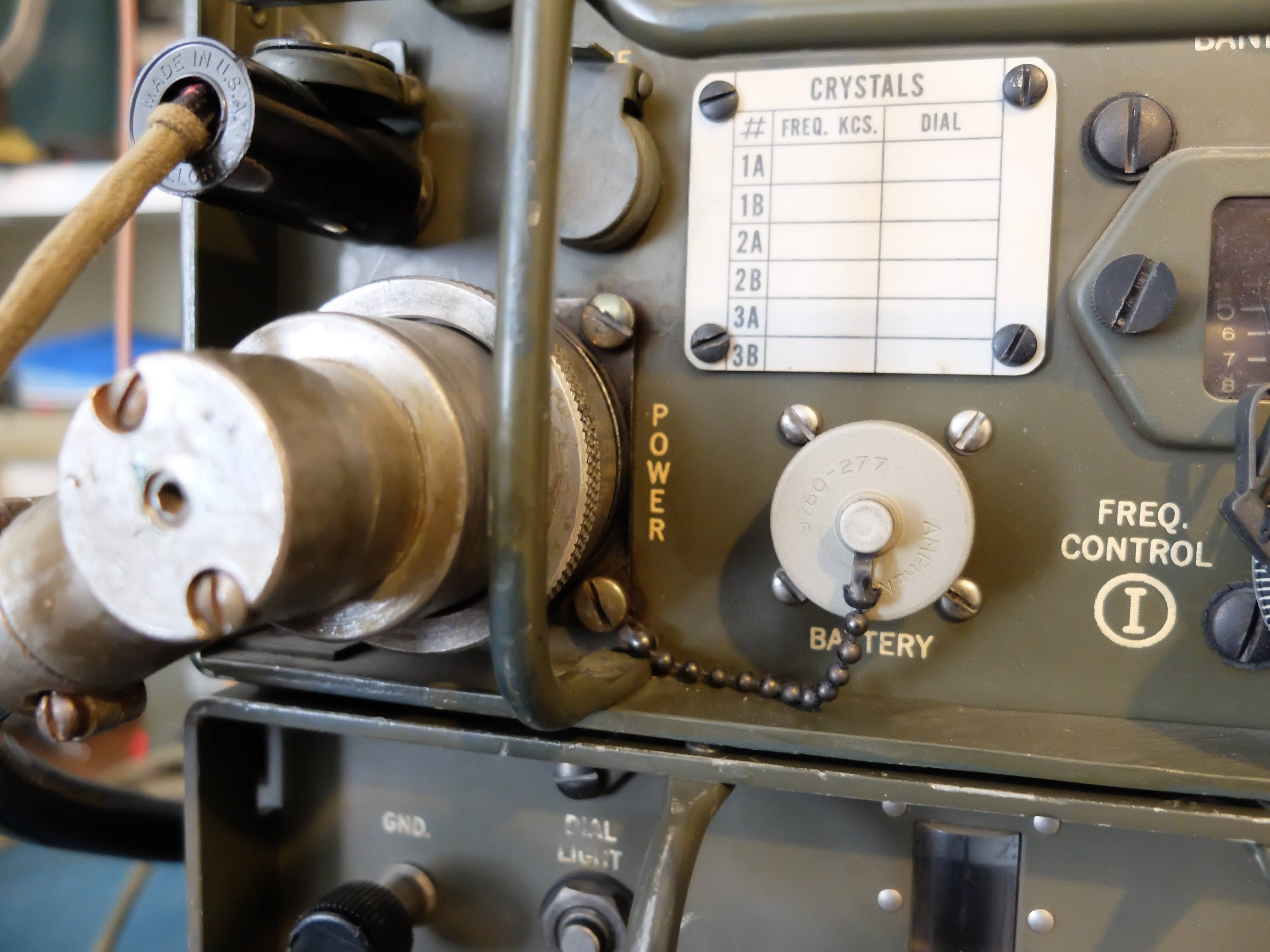
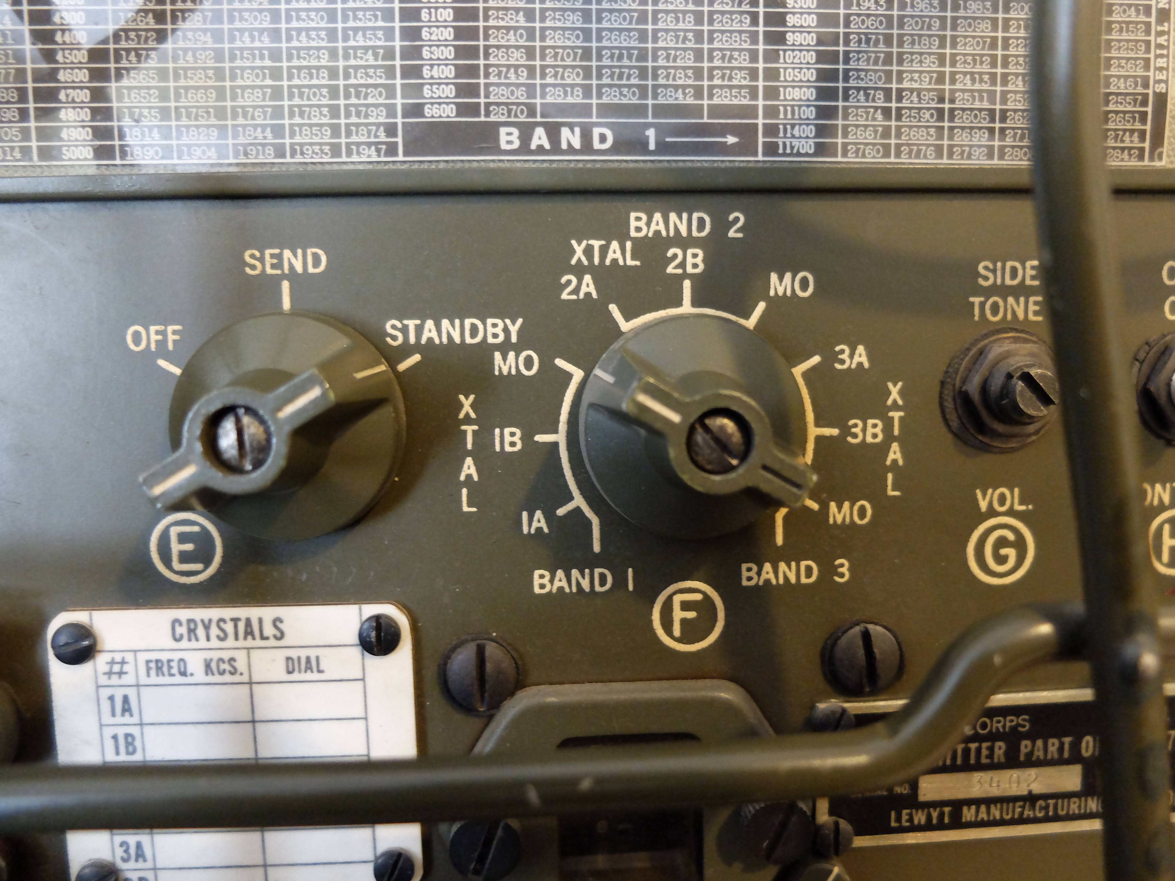
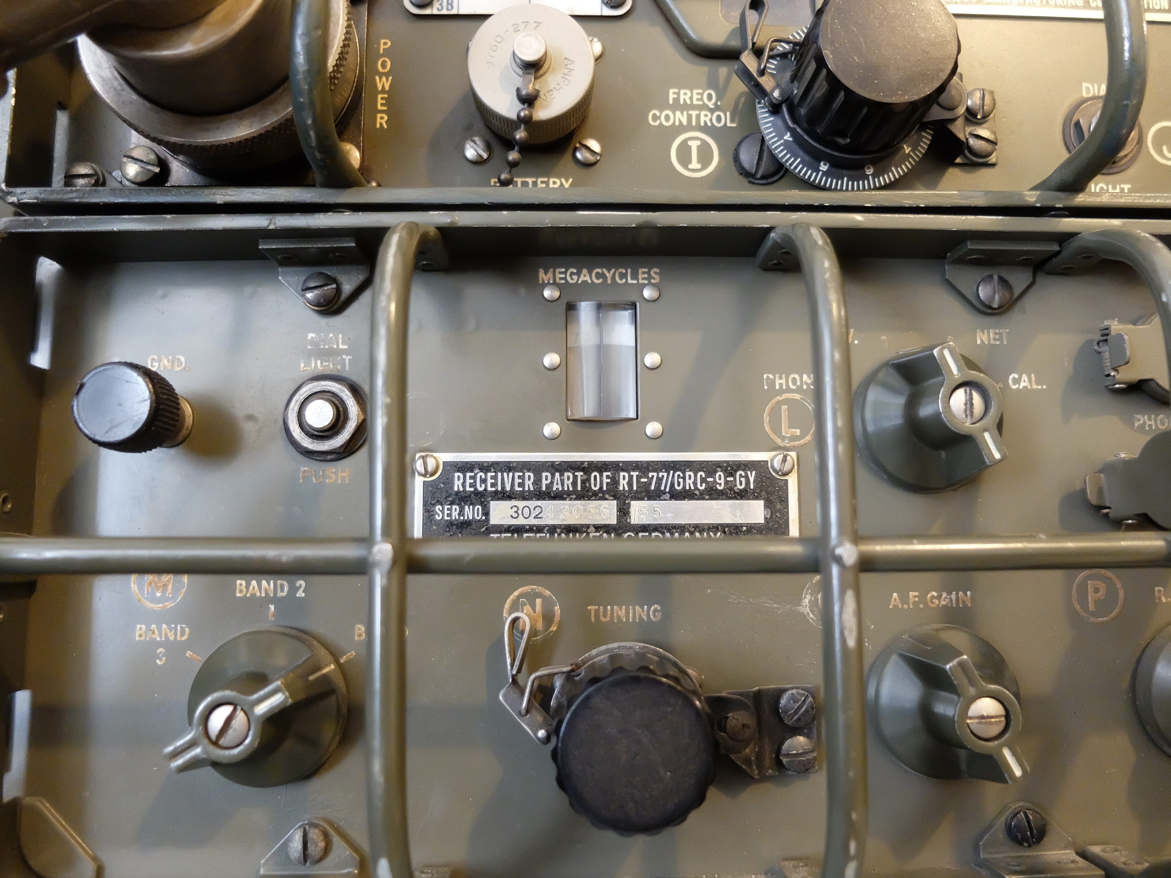
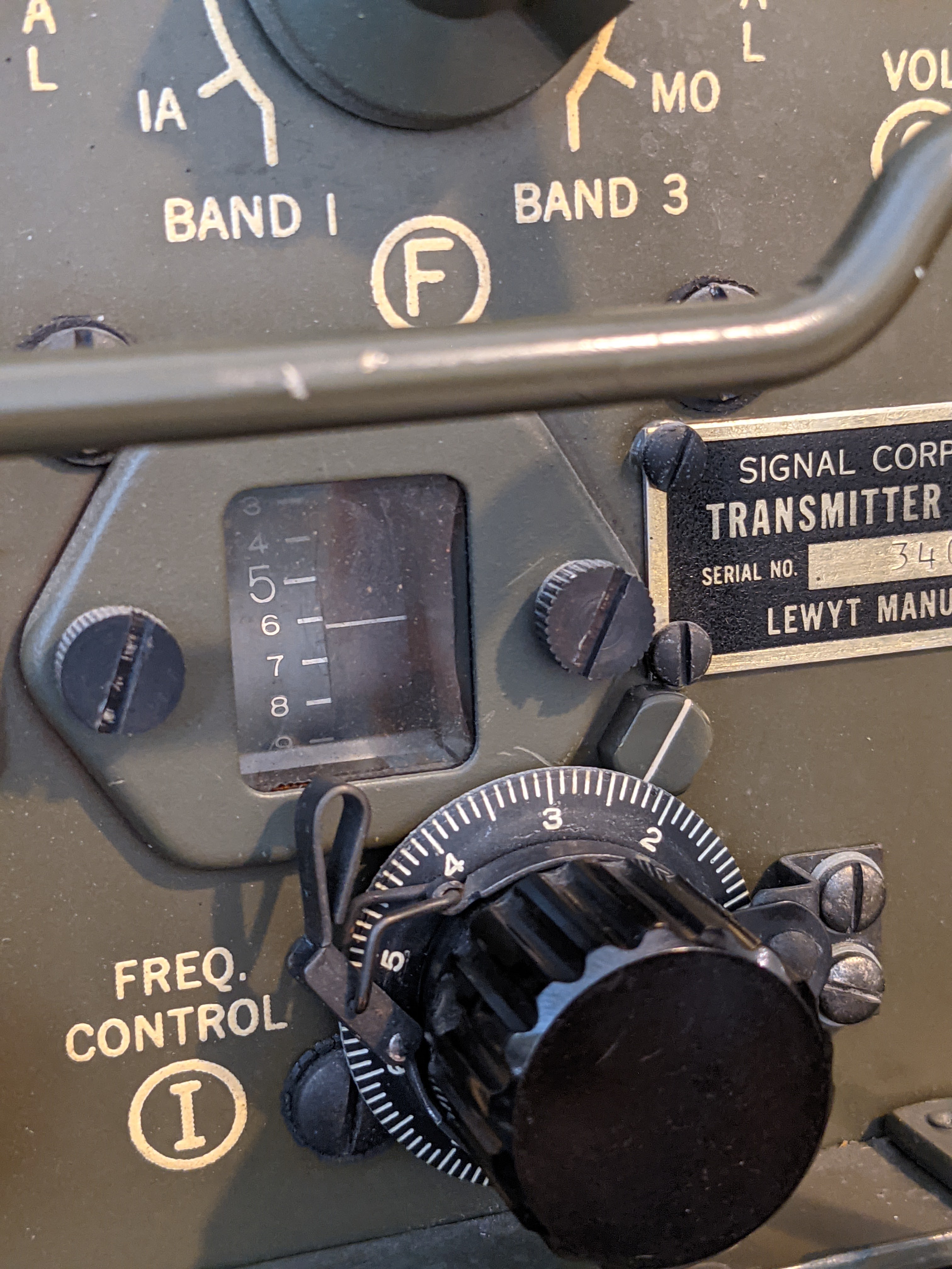
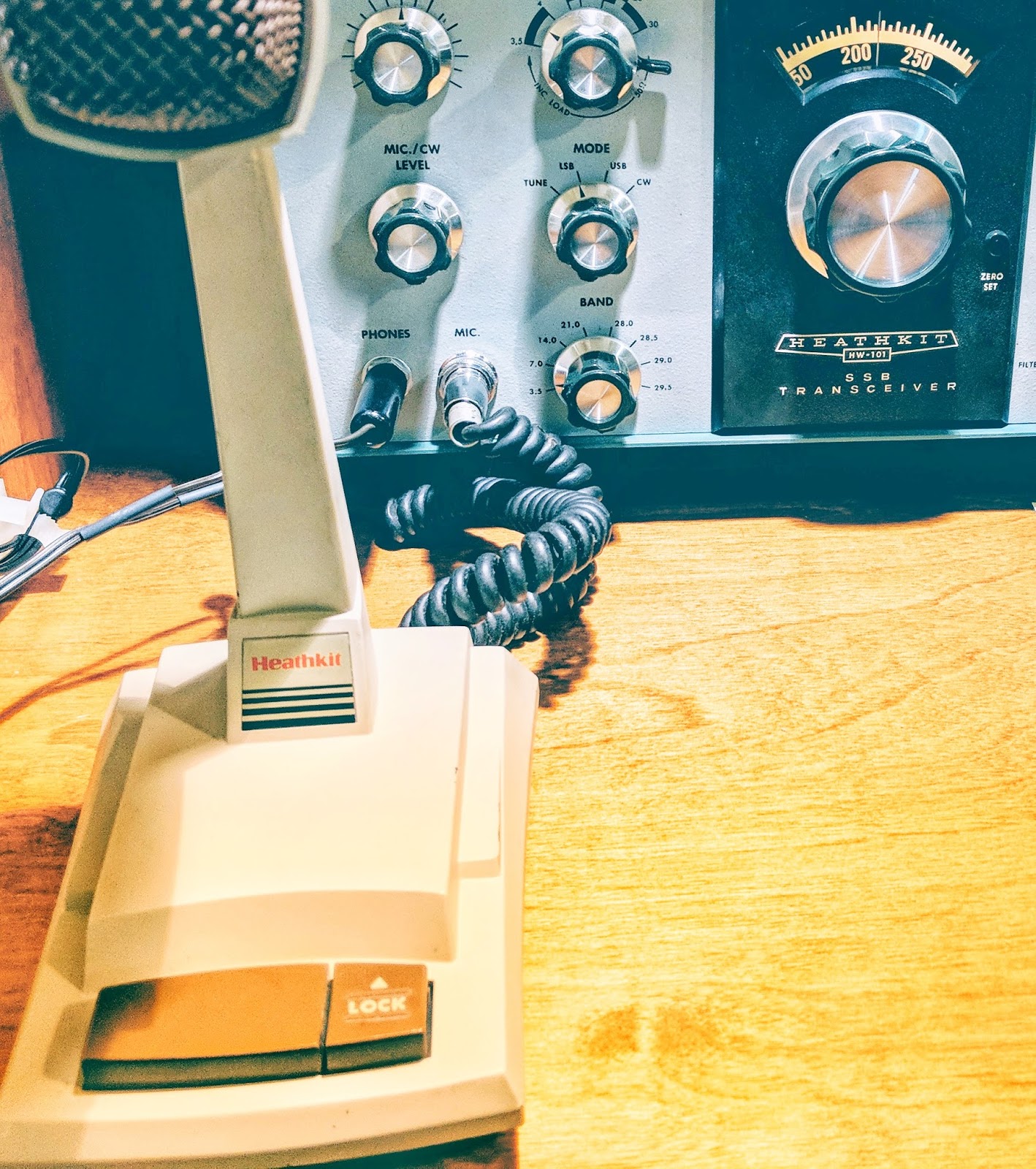
My GRC-9 was designed near the end of WW2 (circa 1945), and was in continuous production for various armed forces around the world until around 1974 (3 decades is a long production run). My particular unit has a receiver manufactured by Telefunken in 1955 and a Lewyt manufactured transmitter from 1966. I have made CW and AM QSOs with other amateur radio operators whose equipment ranged from home-brew xmtr/rcvrs, Drake and Collins radios as well as shiny new Icom 7300 and Flex radio systems.
A modern amateur radio (typically a HF model) can be used to communicate with radios built 100 years in the past. The same might be said for AM fone (phone), but that mode has become a niche for a much smaller set of enthusiasts.
There are lots of new and exciting modes of communication in amateur radio. Many are pushing the boundaries of weak signal reception, or alternatively allow for high transfer rates of data. But it is somehow comforting to me to consider that amateur radio hobbyists have kept one mode in particular, CW, popular and in continuous use for over 100 years using equipment that remains compatible to communicate with one another. I wonder if that will be the case in another century?
That's all for now, so lower your power and raise your expectations
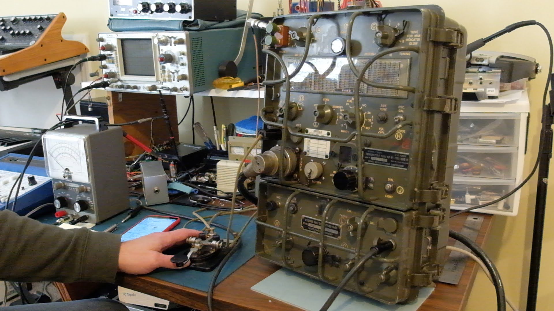
I don't recall where I first read about the Angry Nine, but it captured my imagination. I read everything I could find about them and decided it would be great fun to operate such an antique on the ham bands. There is no logical reason to desire such a QRP radio. The low power output on CW is indeed, 5 watts and high power is a pileup busting 15 watts. The AM transmission are 1 watt and 7 watts respectively. That's almost QRPp for AM mode.
I'd had some experience restoring old tube equipment; my Heathkit HW-101, Knightkits VFO and Hallicrafters keyer, and I figured I'd take the next plunge and learn to use a receiver-transmitter combination and see how mobile high-voltage power worked from Vibrators and Dynamotors.
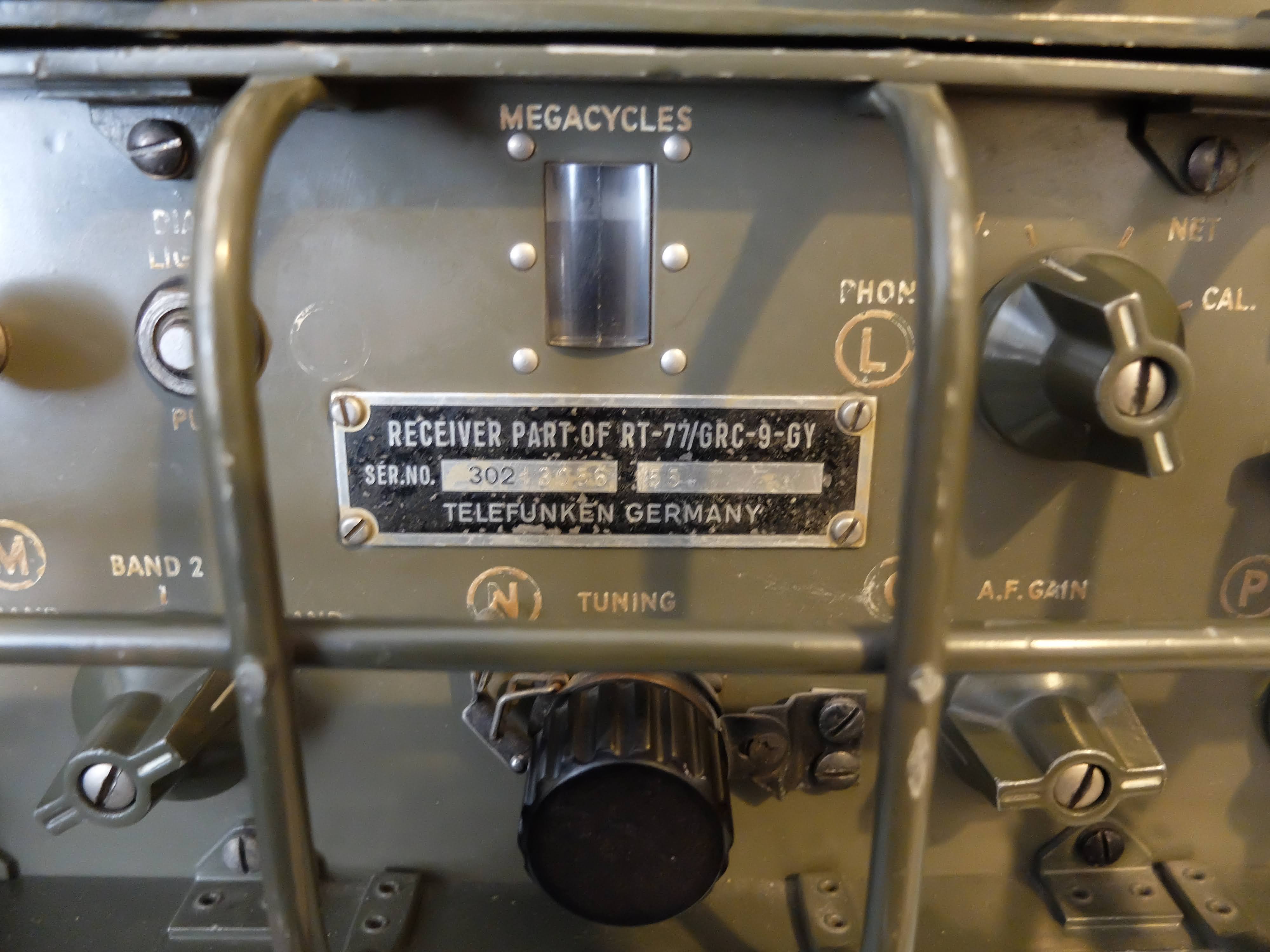
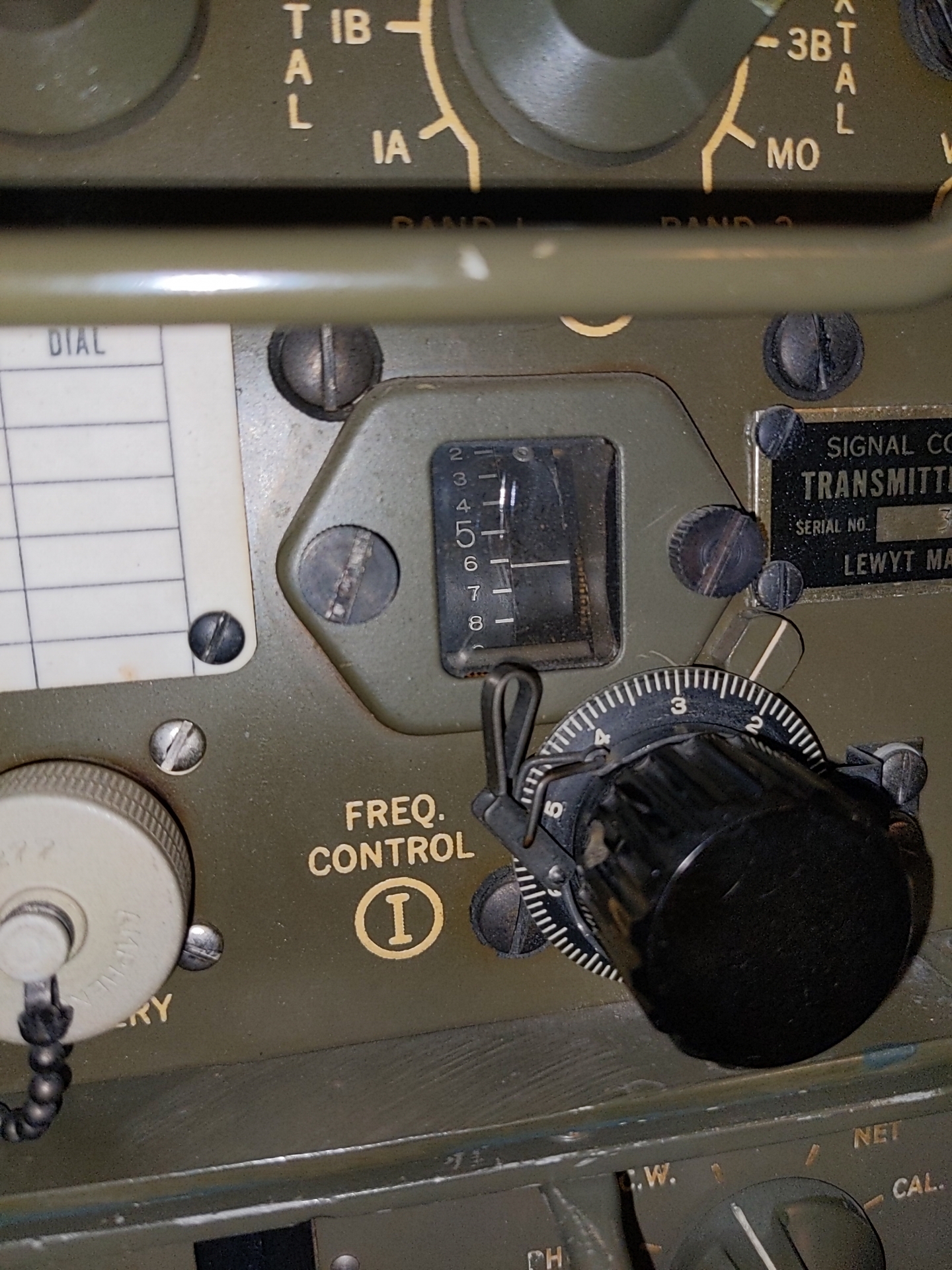
These radios seemed to have been more plentiful in the surplus market 10 - 20 years ago. Now you'll occasionally see one come up on eBay or other sites, but often times they are in very rough shape or the they are foreign language versions. I bid on a few auctions over the past couple of years and the bidding always exceeded my threshold for what I thought it was worth. The one above was part of an auction from an individual who had actually trained on these units prior to deploying to Vietnam. Later in life he became interested in finding one and spent time in military surplus warehouses going through pallets of equipment to find one in good shape. This particular unit is made up of a Lewyt manufactured transmitter and a Telefunken receiver. The original owner preferred the receiver characteristics of the Telefunken over the Lewyt manufactured model, so he paired the two.
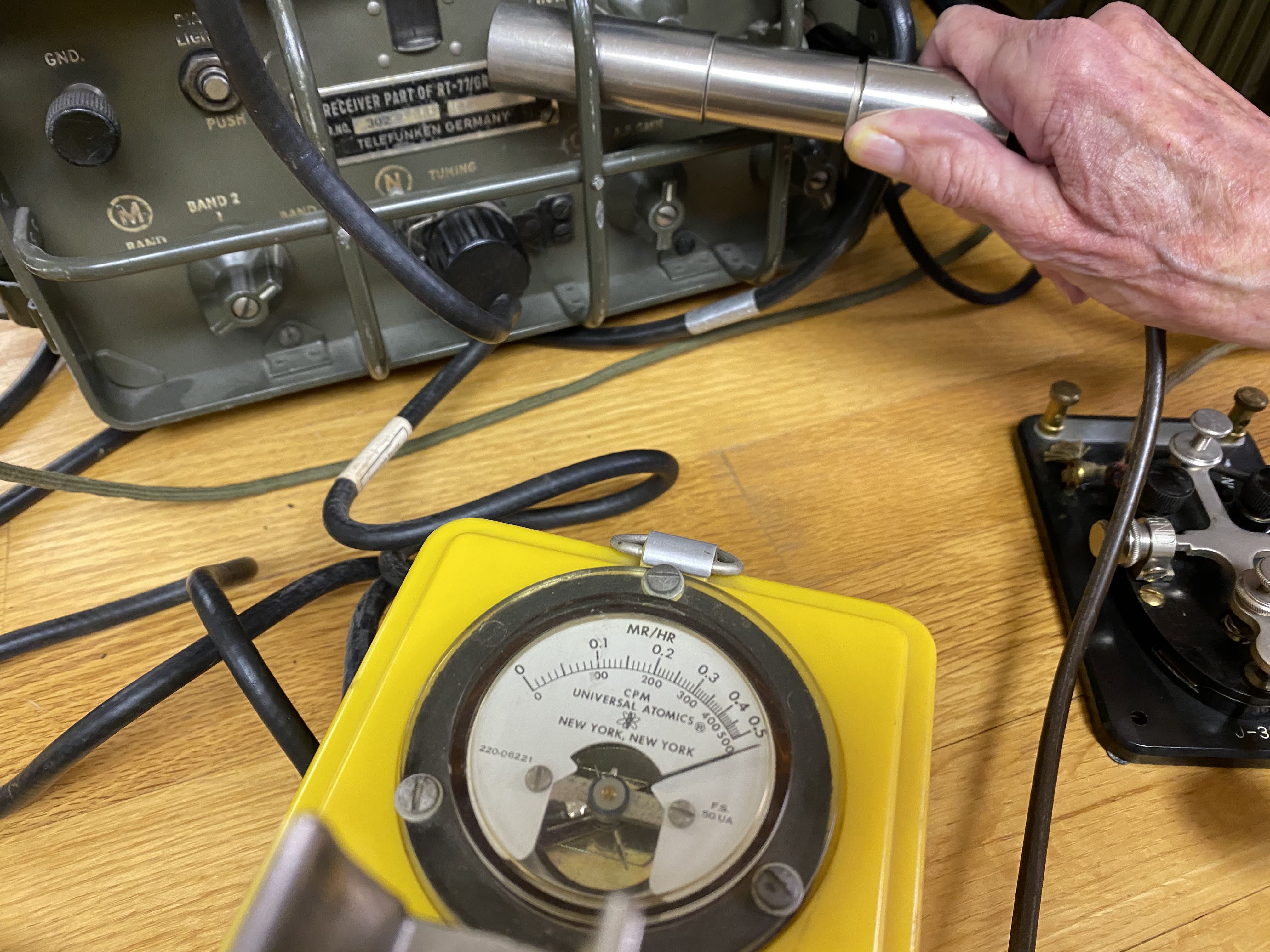
Many of these old units are radioactive, due to the radium paint used on the front panels to make the lettering glow in the dark. This particular unit is off the lower scale on the Geiger counter and must be handled with care. Basically, I have to be careful to not touch my face with my hands after operating the unit and wash my hands thoroughly. Radium emits Alpha particles, which are not especially strong but the resultant radioactive dust from the front panel shouldn't be breathed or ingested. I plan to paint a clear-coat over the remaining lettering to lessen the Alpha particle emissions..
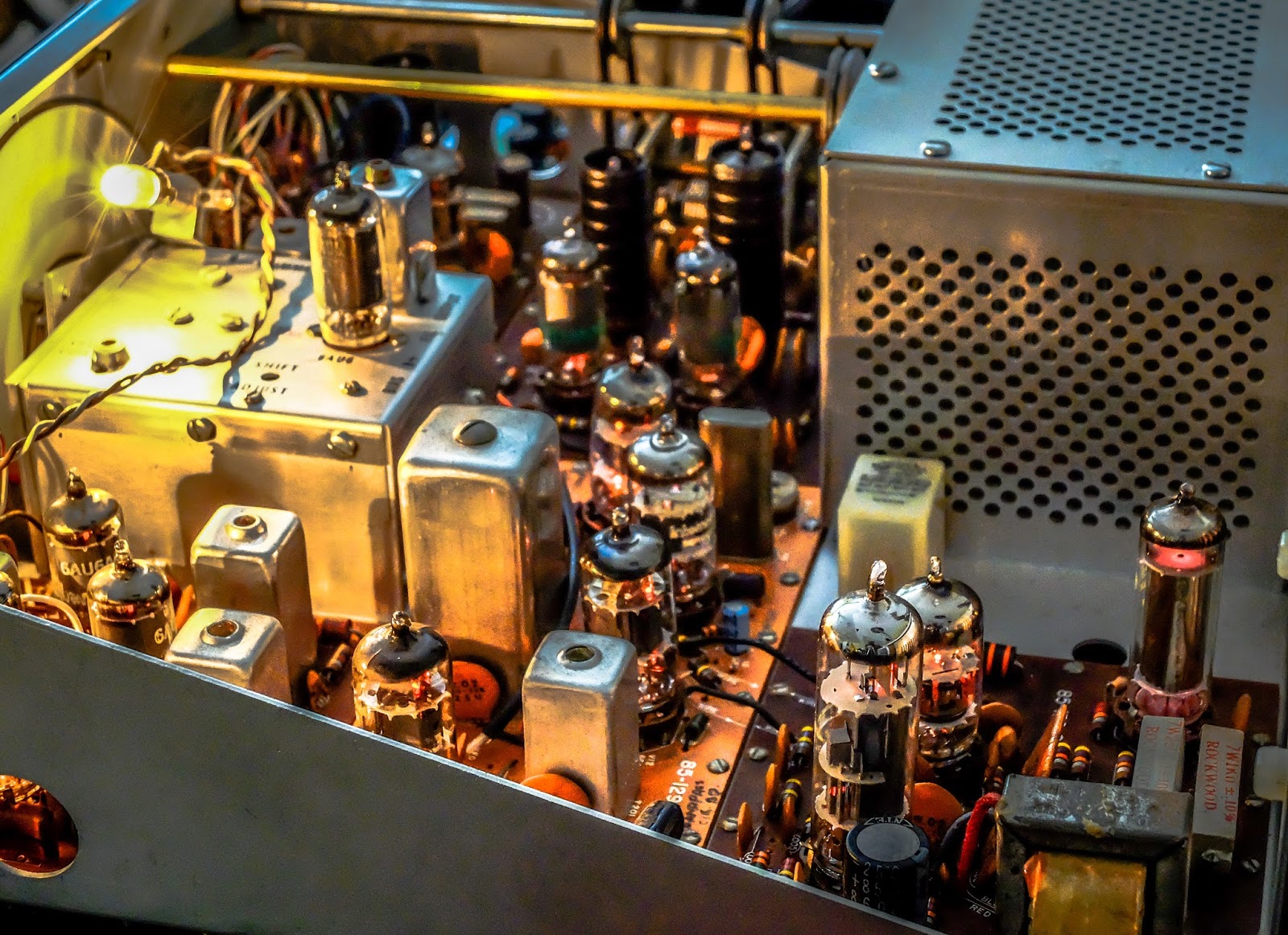
Hot receiver, in more ways than one
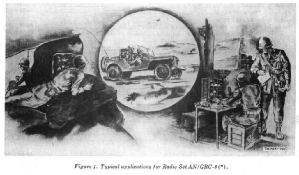
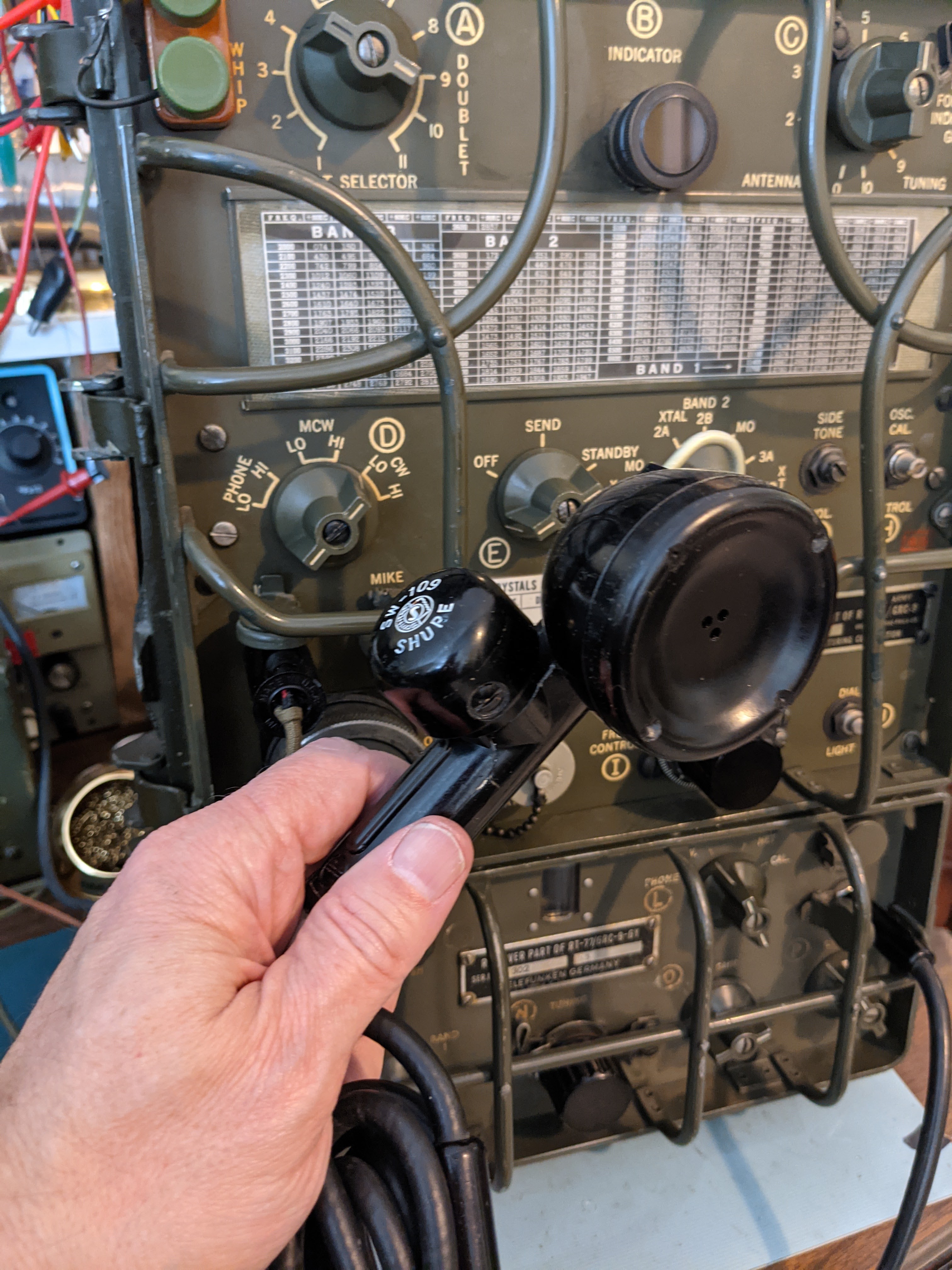
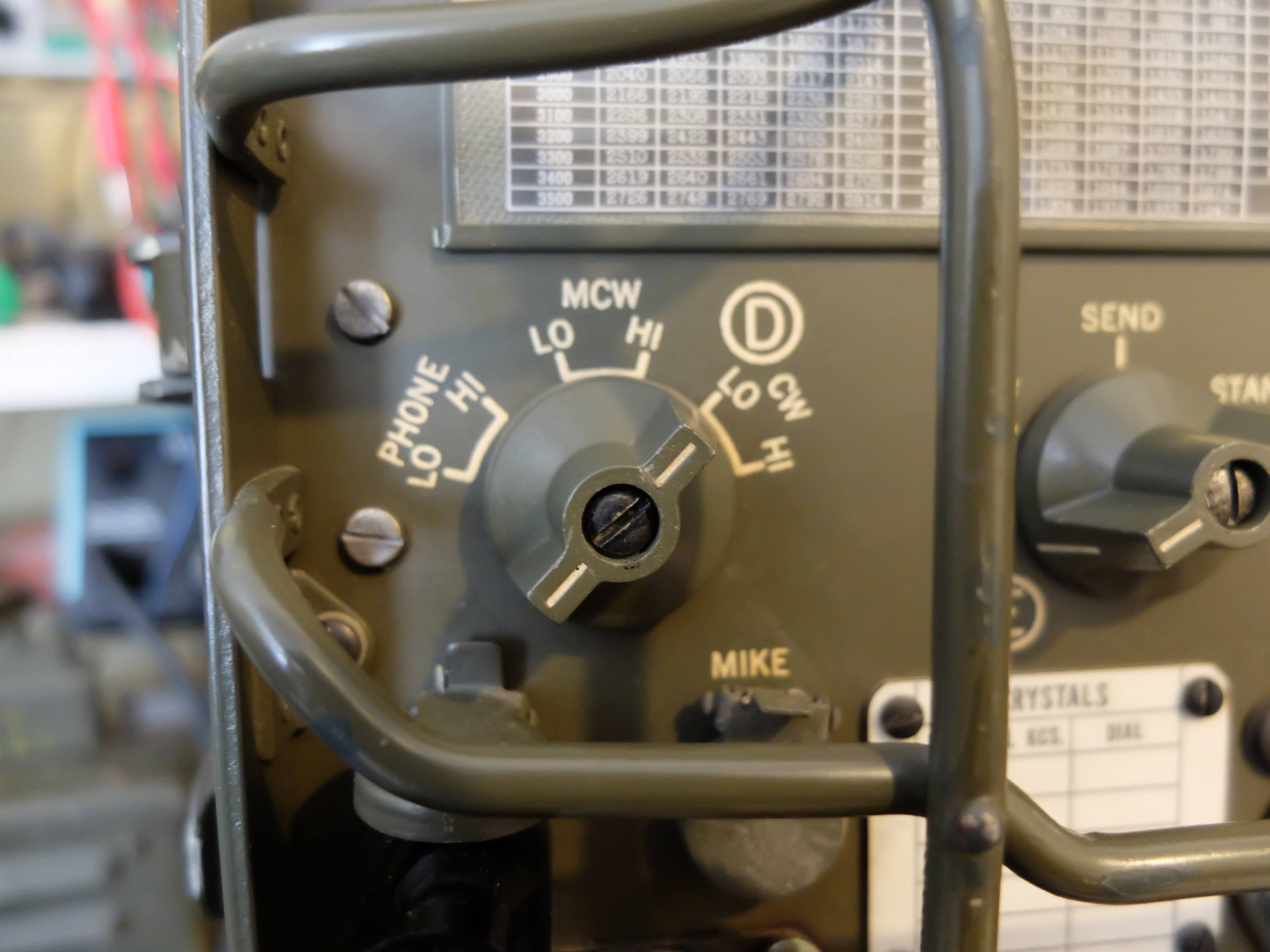
The AN/GRC-9 is a set of components primarily comprised of the RT-77/GRC-9 receiver-transmitter, capable of operating between 2-12 MHz in CW, MCW and AM modes. MCW is a modulated form of CW that can be received by radios that do not have a BFO (i.e. a normal AM receiver).
It is a mid to late 1940's design and was first documented field use in the Korean War, and was in active use through the Vietnam War and continued to be maintained in US military warehouses until 1974. It was in use by other nations long after, most notably the Dutch military.
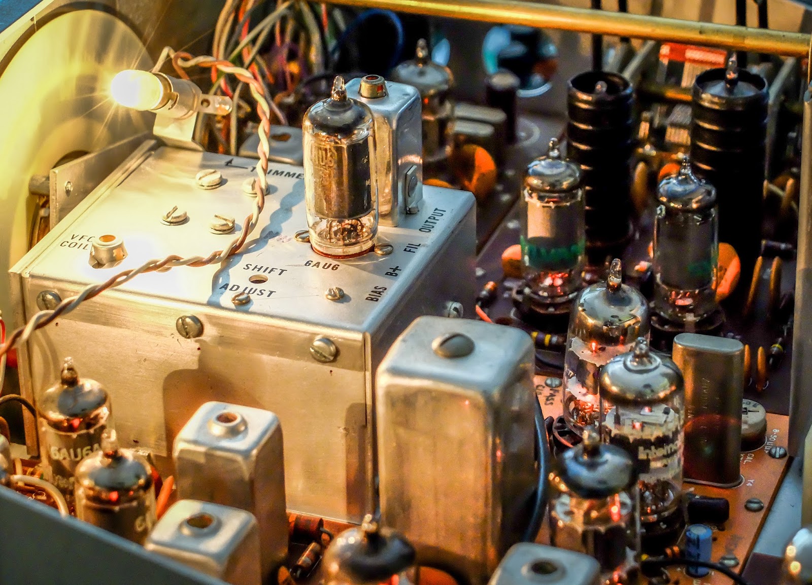
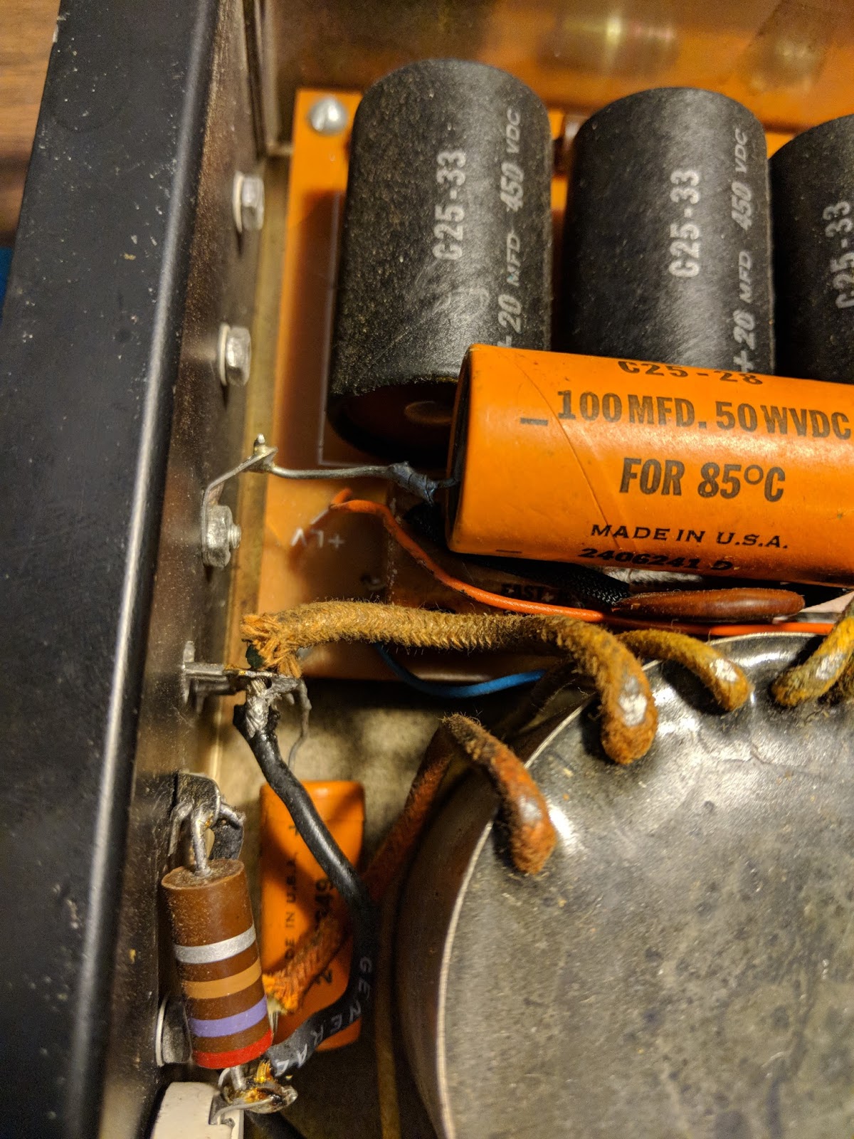
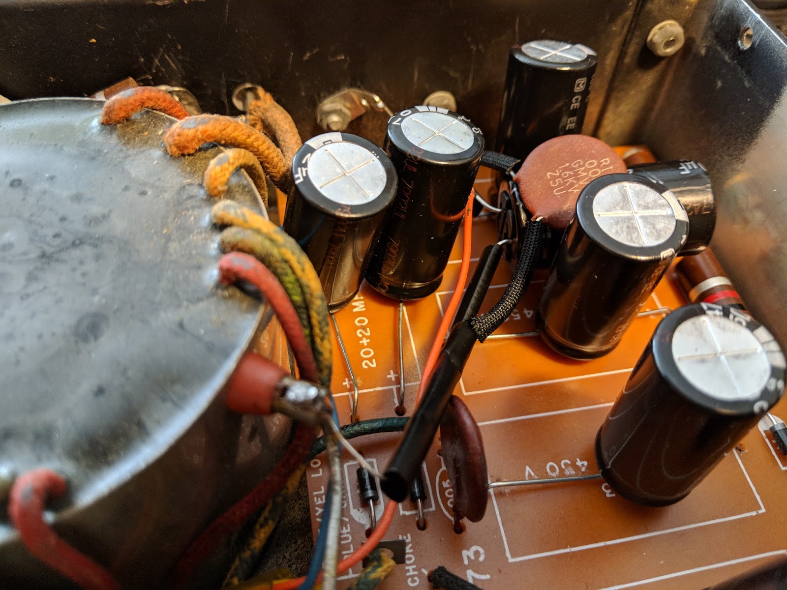
Out of the case, tracing a low B+ power problem
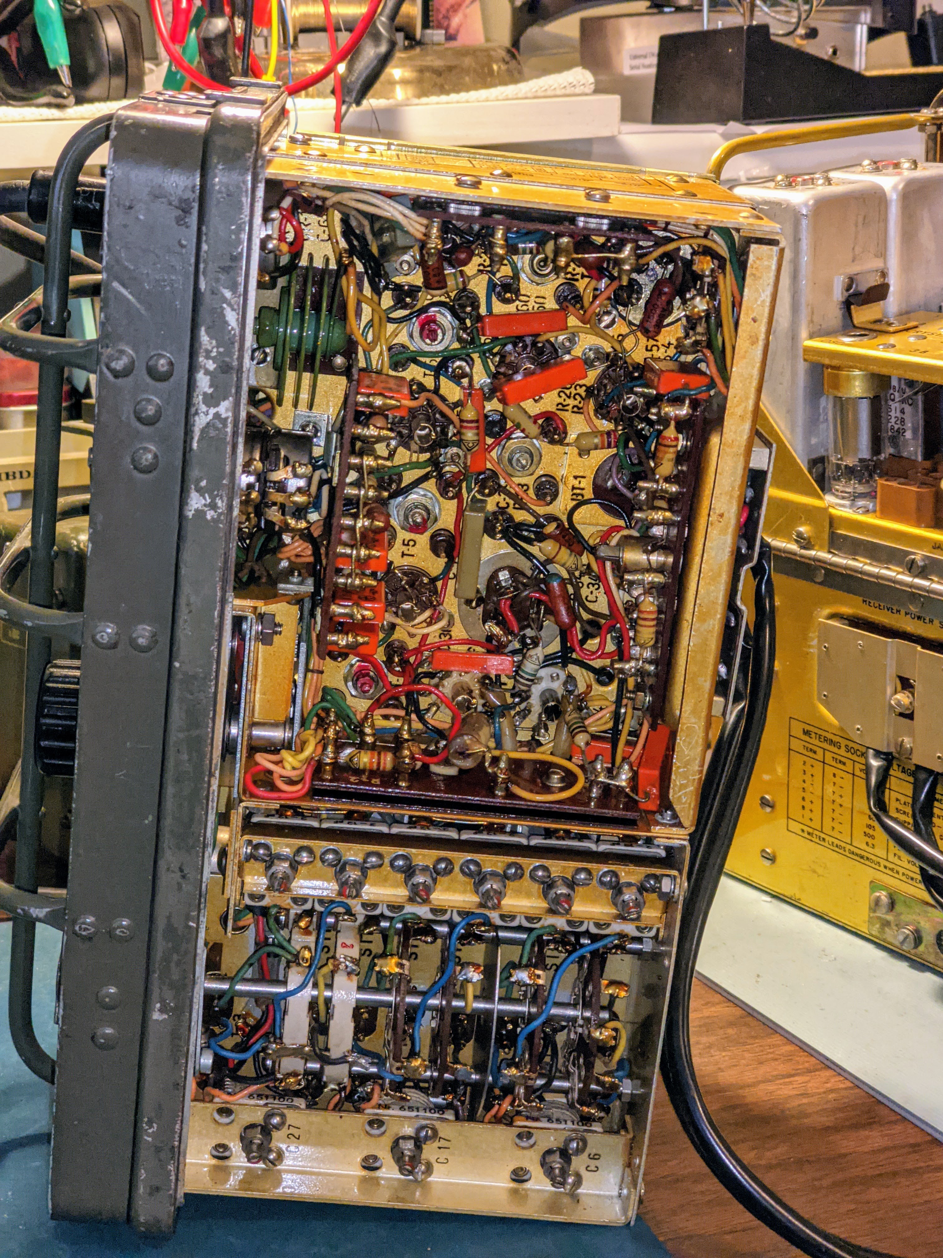
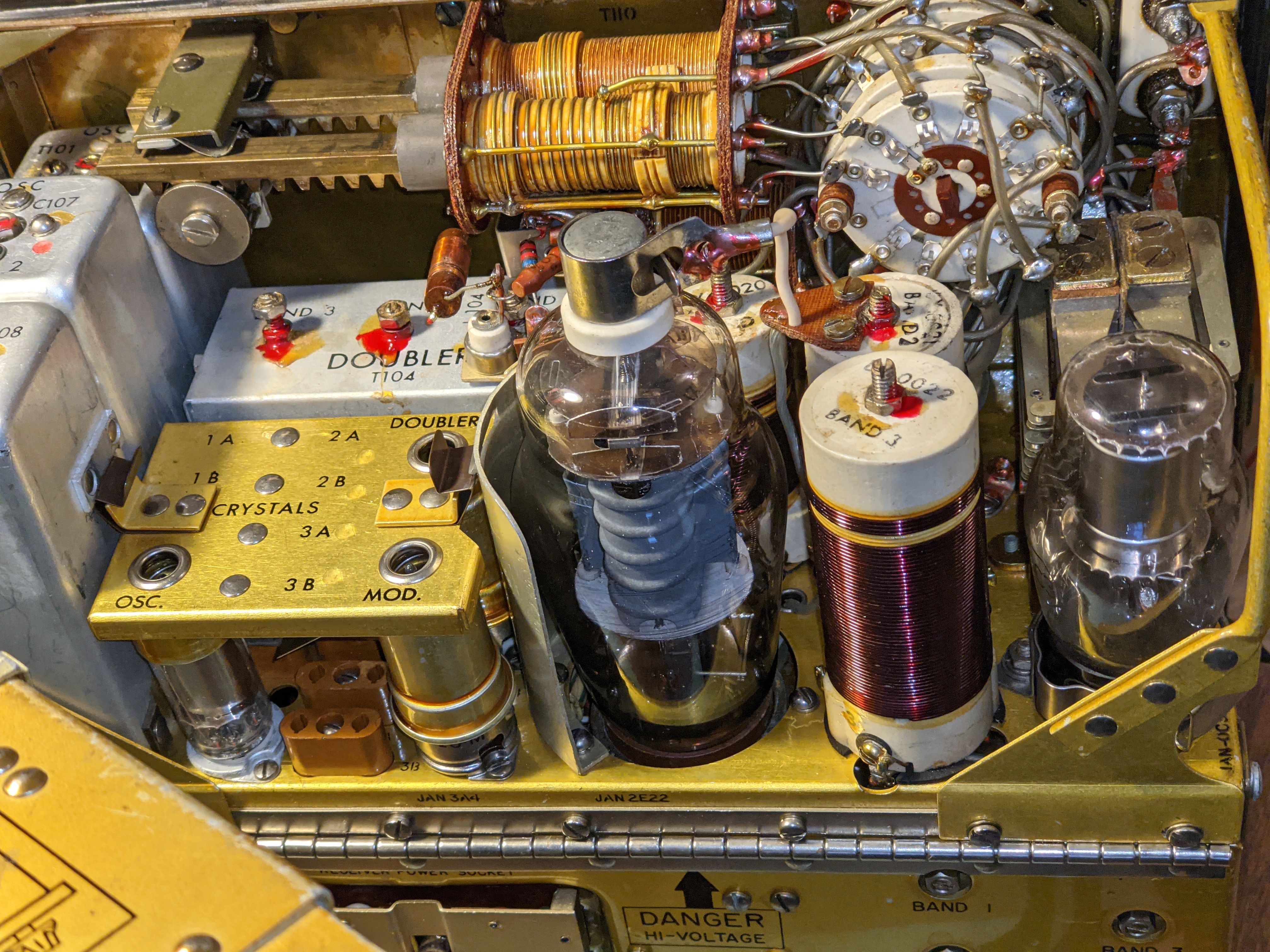
Receiver as seen from the underneath with shield removed
Transmitter with a coil for each band and that nice 2E22 final output tube
Power on the move
Designed to be used in the field, both vehicle mounted and carried by mobile infantry; there were a number of ways to supply power to the unit. There were a few different Vibrator/Dynamotor units, that could operate from common DC voltages of the time (6v, 12v, 24v) as well as a hand cranked, field portable generator.
Keep in mind that the state of the art at the time of its design used vacuum tube technology and in the case of the RT/77-GRC/9 it required the following voltages:
Transmitter Plates -- 475 - 580 v @ 100ma
Transmitter Filaments -- 6.5 - 6.6 v@ 2 amps
Receiver Plates -- 105 - 120 v @ 45ma
Receiver Filaments -- 1.35 - 1.5 v @ 500ma
Keying Relay -- 6.0 - 6.9 v @ 575ma
That's a tall order for mobile and portable power supplies but designers in the 1940's were quite clever in packing power supply units. I managed to obtain both the hand cranked GN-58 generator with the base chassis and seat for portable operations, and a DY-88 for fixed / mobile operations.
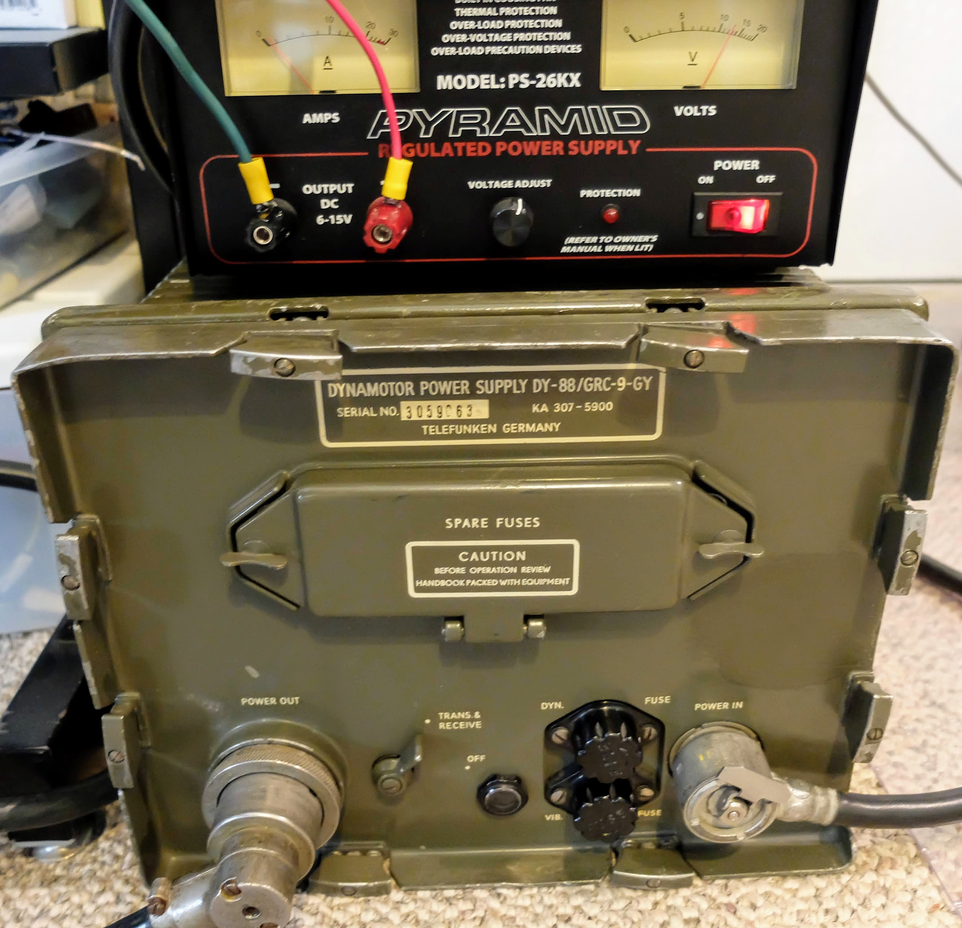
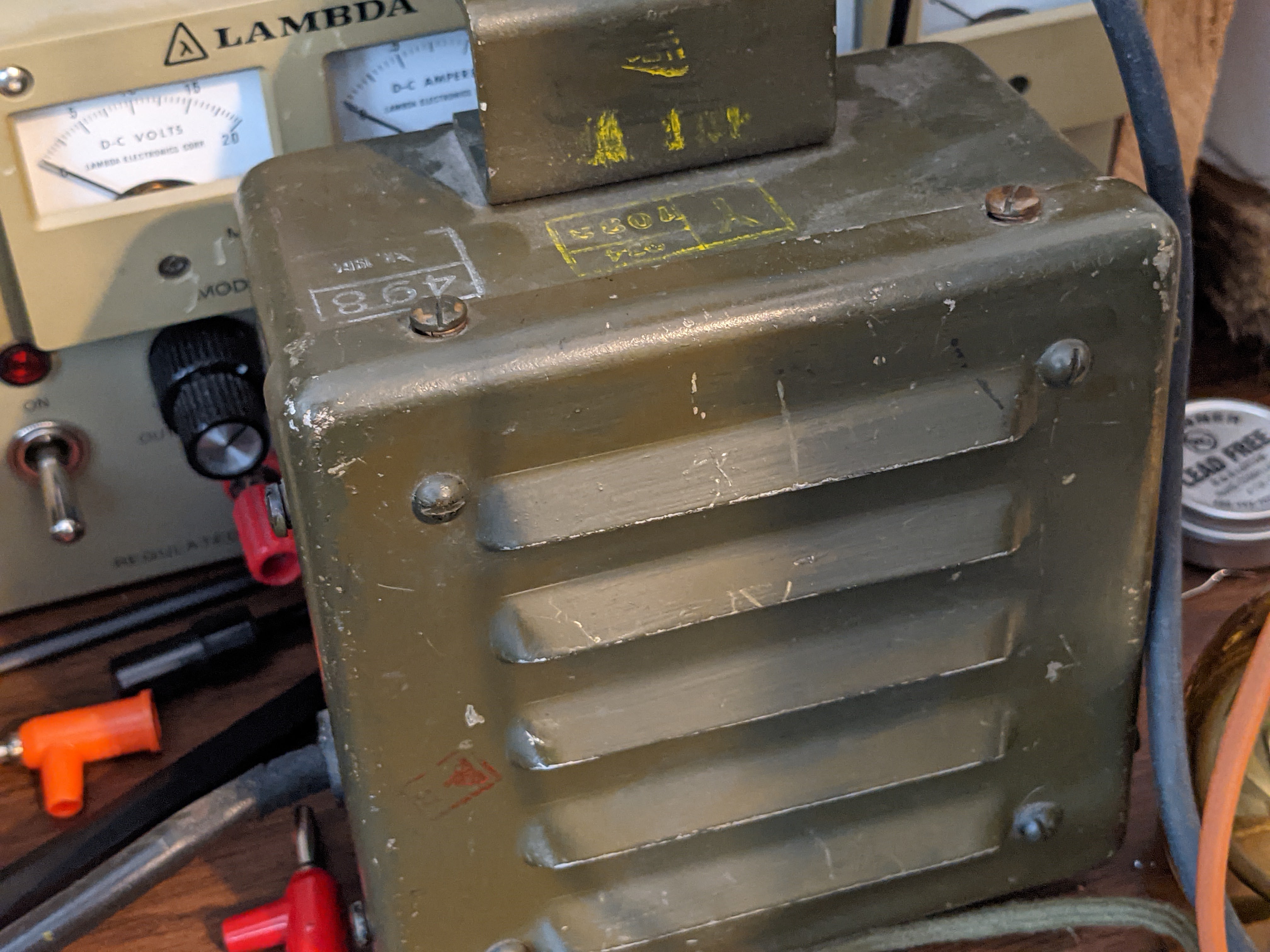
DY-88 mobile power supply
DY-88 set to 12v powered by Amateur 12v supply
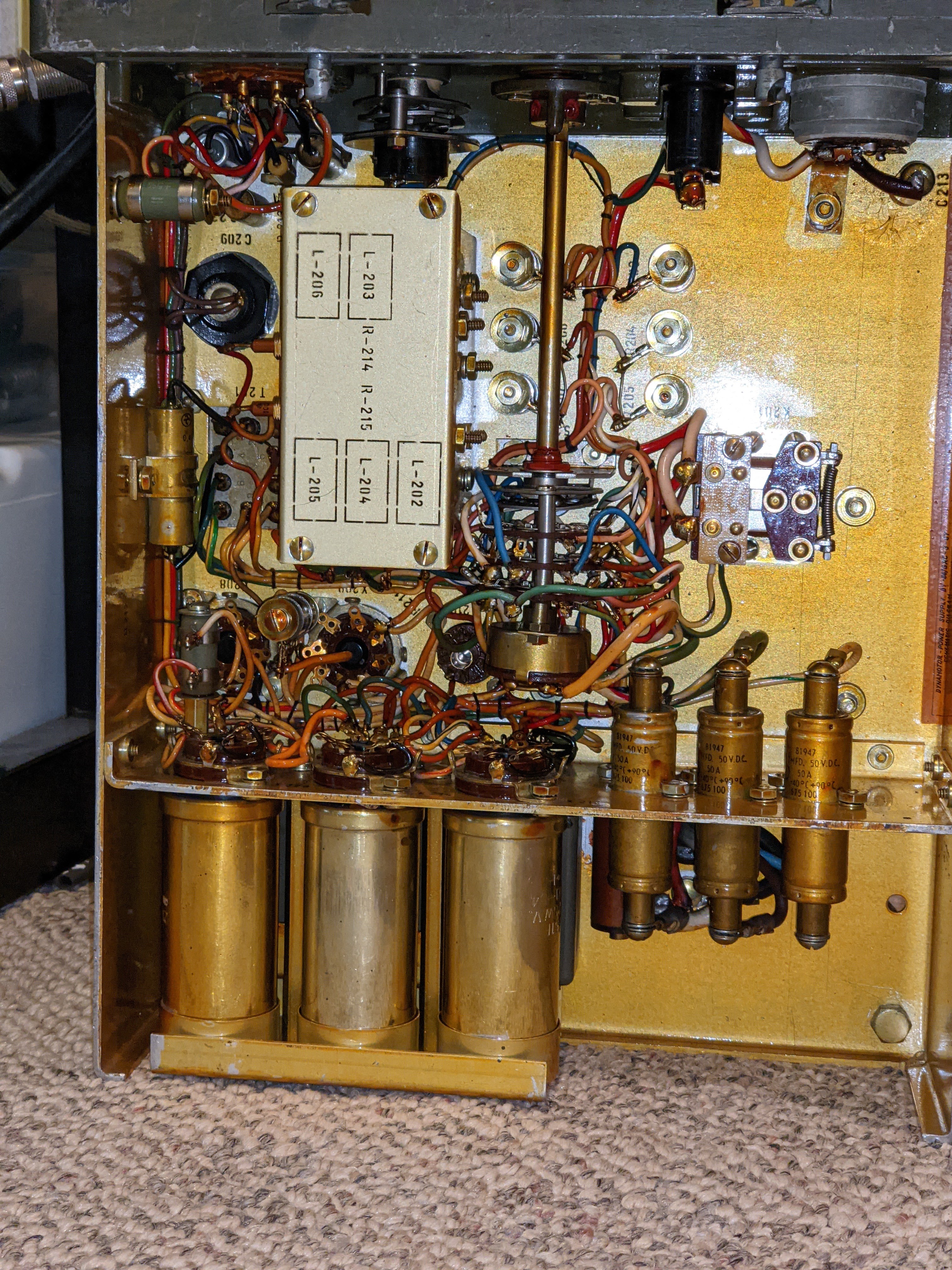
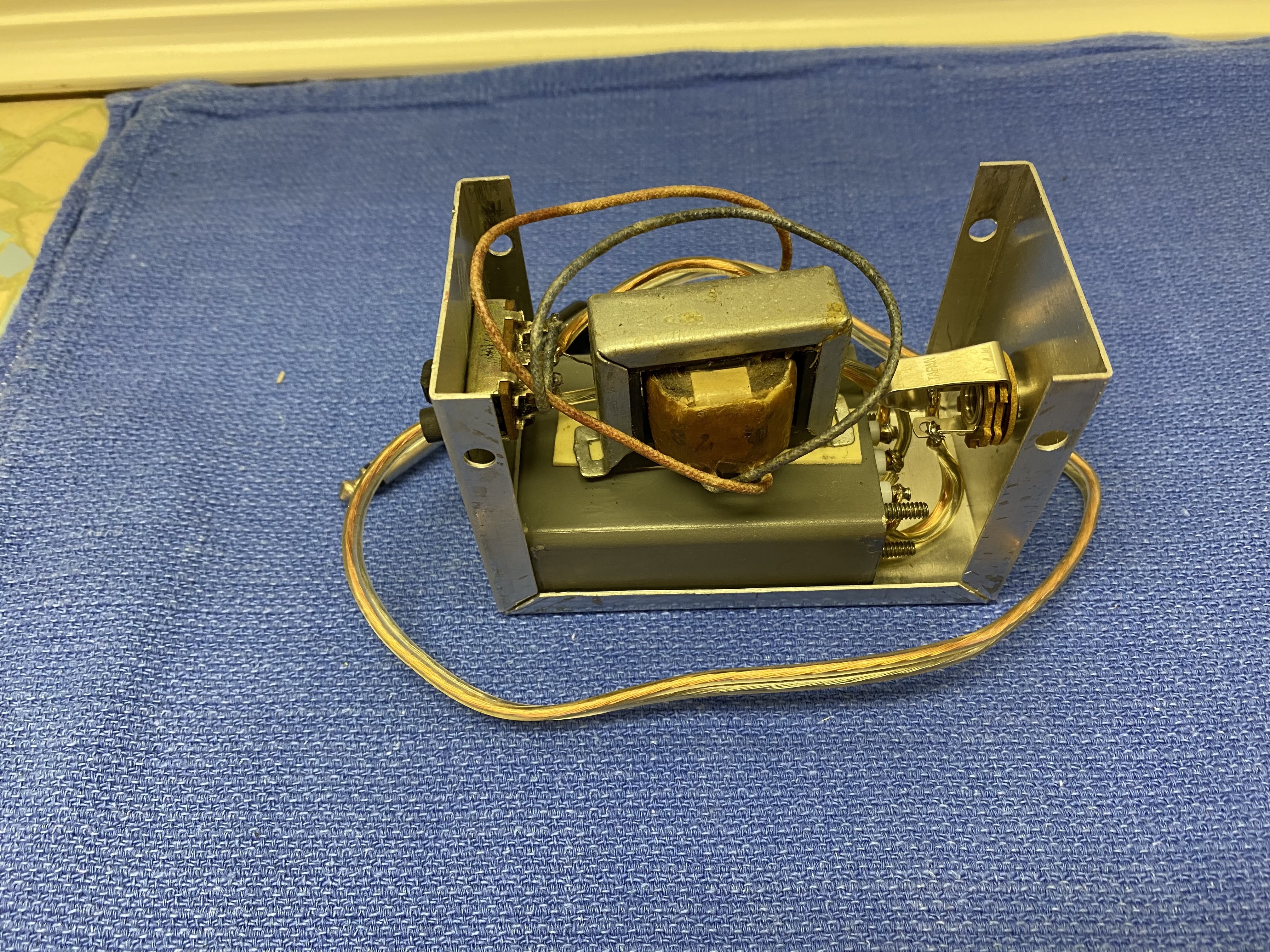
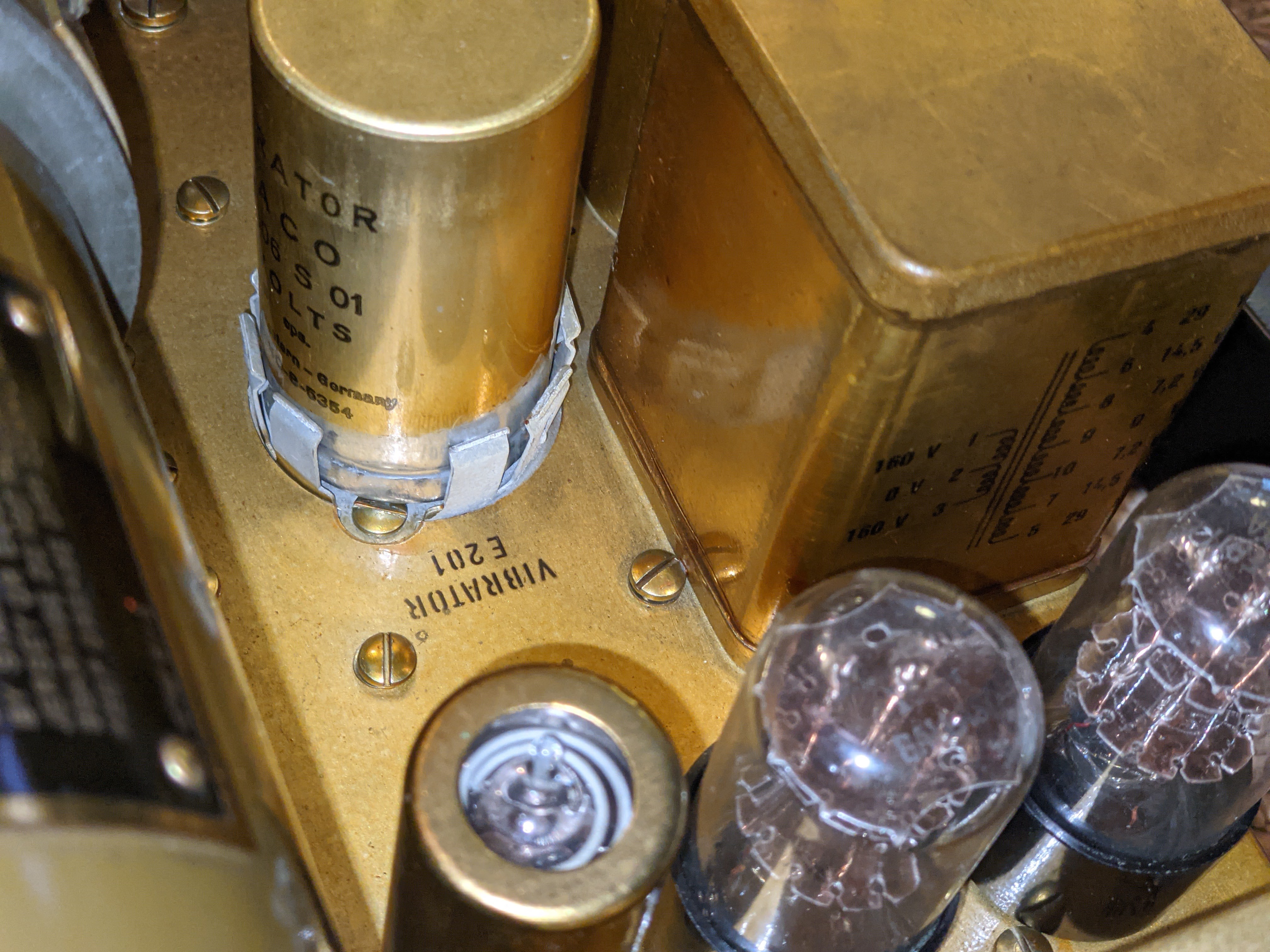
Vibrator power supply for low B+
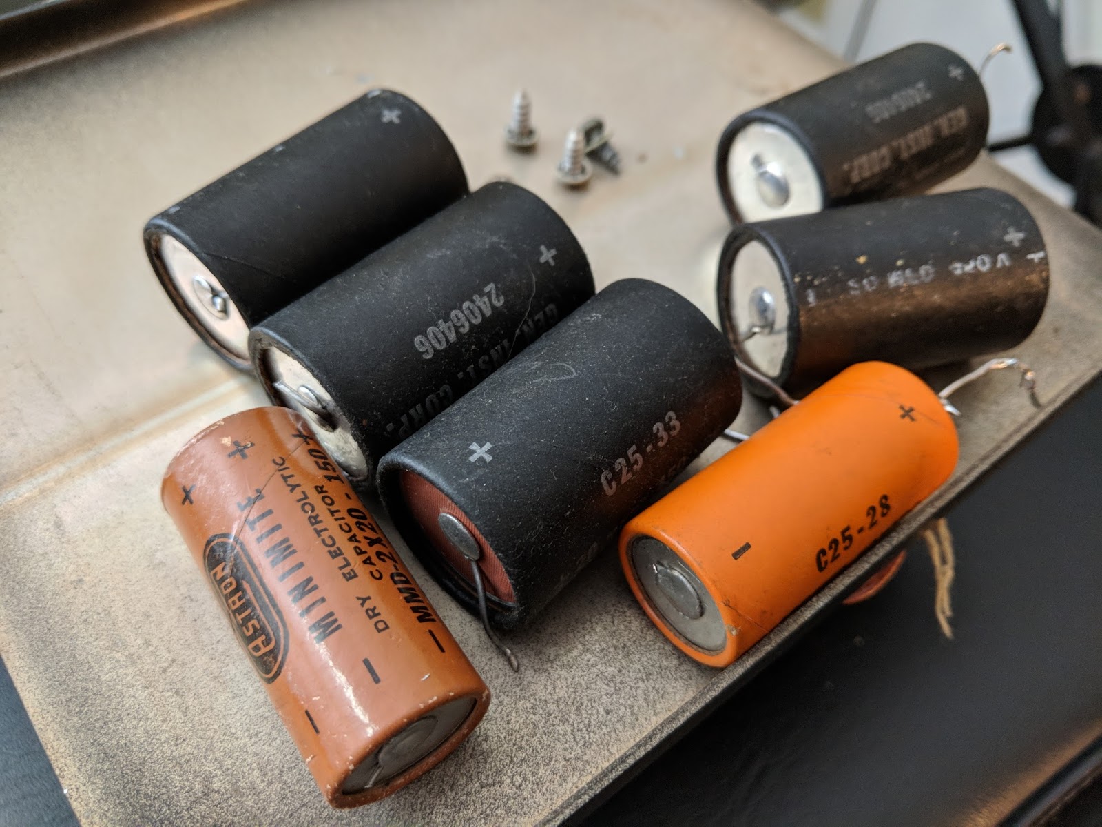
Power filtering
I supply the DY-88 from either an RV battery or an amateur 12v power supply. When in Standby the DY-88 draws less than 1 amp, but placing the radio in Send mode switches on the Dynamotor which draws 12 amps @12v, without key-down and up to 14 amps on high-output key-down. It will drain an RV battery pretty quickly at that rate if the radio is left in Send mode, and works an amateur power supply pretty hard as well. So don't expect to operate remote off a battery alone for too long if your having lengthy QSOs. An added benefit of the DY-88 is that when the enclosed Dynamotor is running you'll have a nice extra 85 dB of generator noise to accompany your listening pleasure.
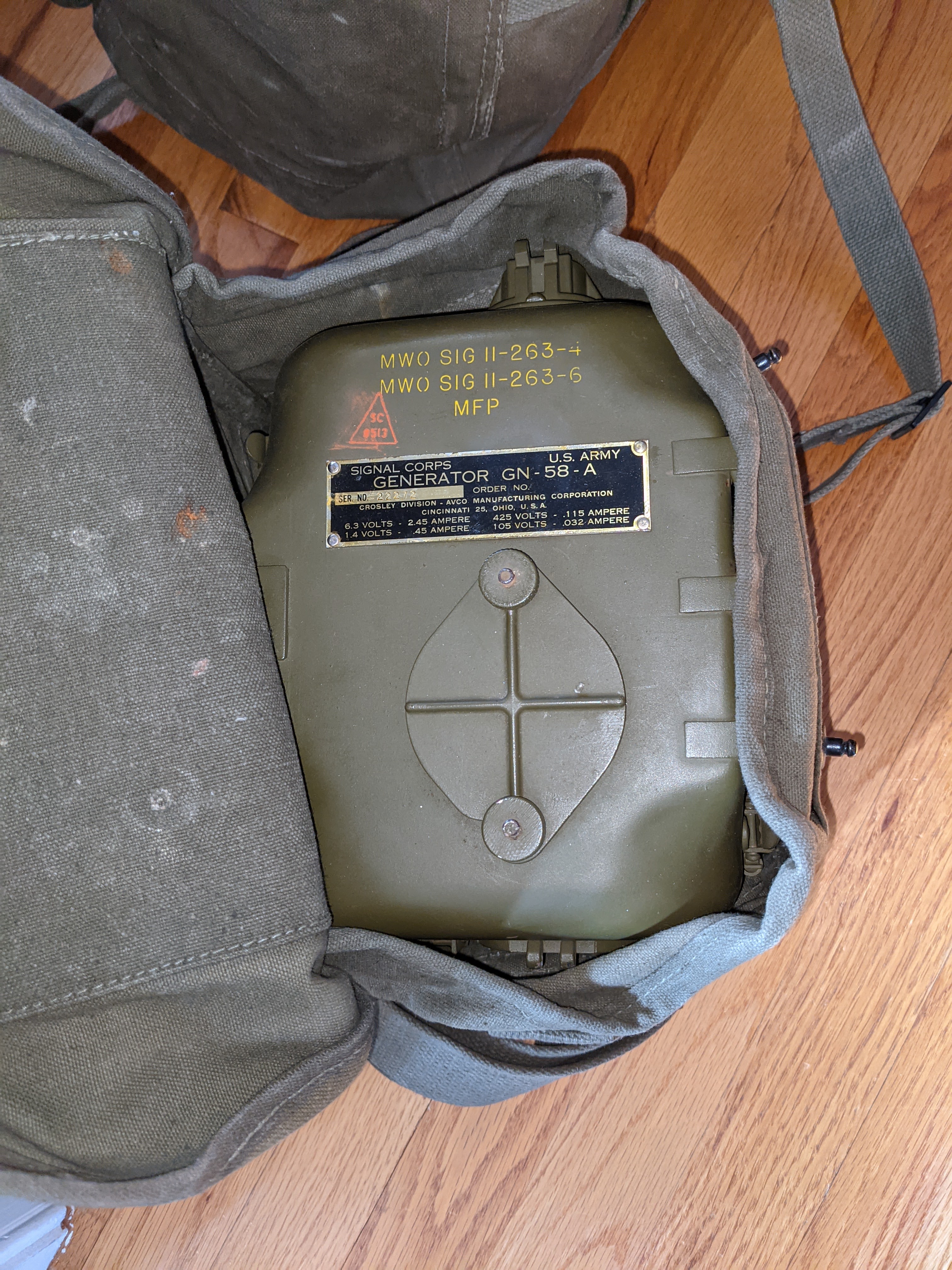
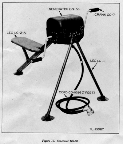
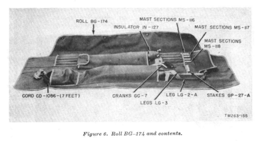
GN-58 portable field hand-cranked power supply
Generator head in carry bag
Unmounted as seen from the bottom
On the stand with cover and handles disconnected
Deployed
The GN-58 is a tough workout since it has to be cranked by hand at 60 rpm continuously. Obviously, you need a partner unless you can figure out how to crank it with your feet while sending CW. You will also want that partner to help you carry the GN-58, and the accompanying accessory bag for the chassis and seat. IT'S HEAVY. I haven't weighed everything, but according to the manual that came with the set, the radio / generator / accessories including antennas comes out around 120 lbs.
If you have a BA-48 battery hooked up then your human power supply can pause cranking while your receiving. I have a BA-48 battery enclosure that has been gutted of the original, long-dead material and replaced with 10x 9v batteries in series for the low B+ and two D-Cell batteries in parallel for the receiver filament supply.
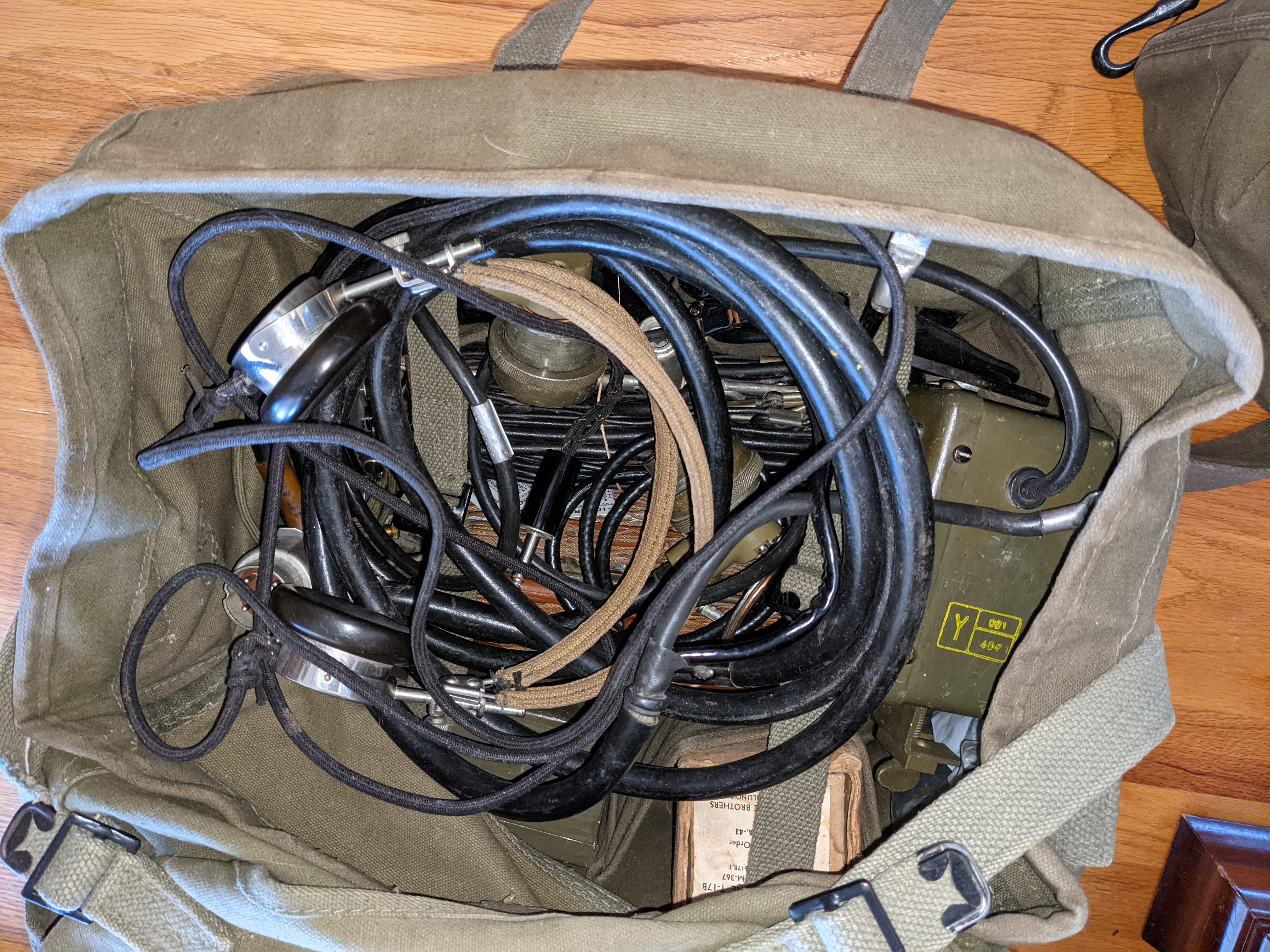
Accessories
Bag of goodies
The radio itself has a carry bag, as well as a bag for the GN-58 legs and seat, the vertical antenna, and miscellaneous.
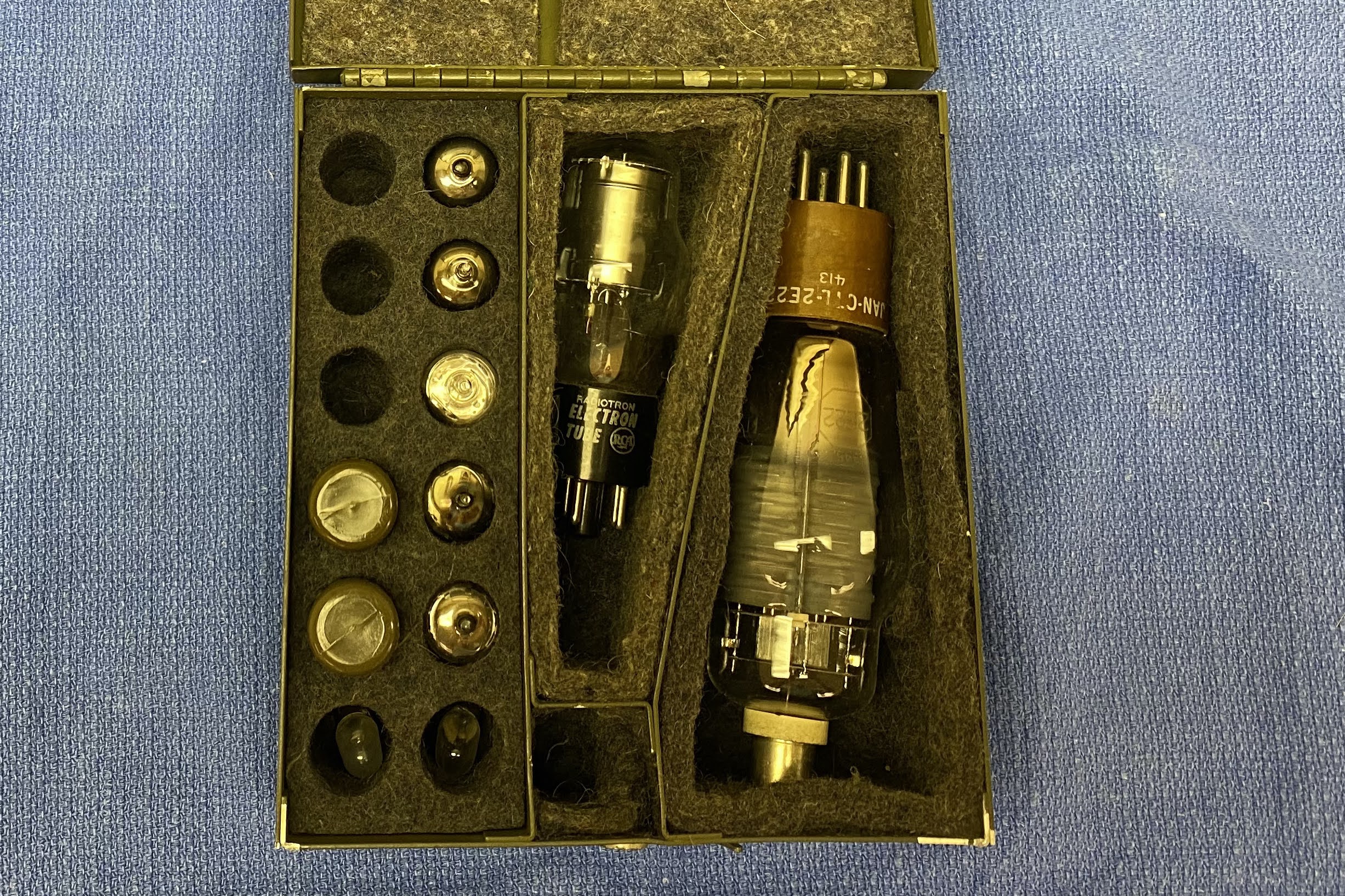
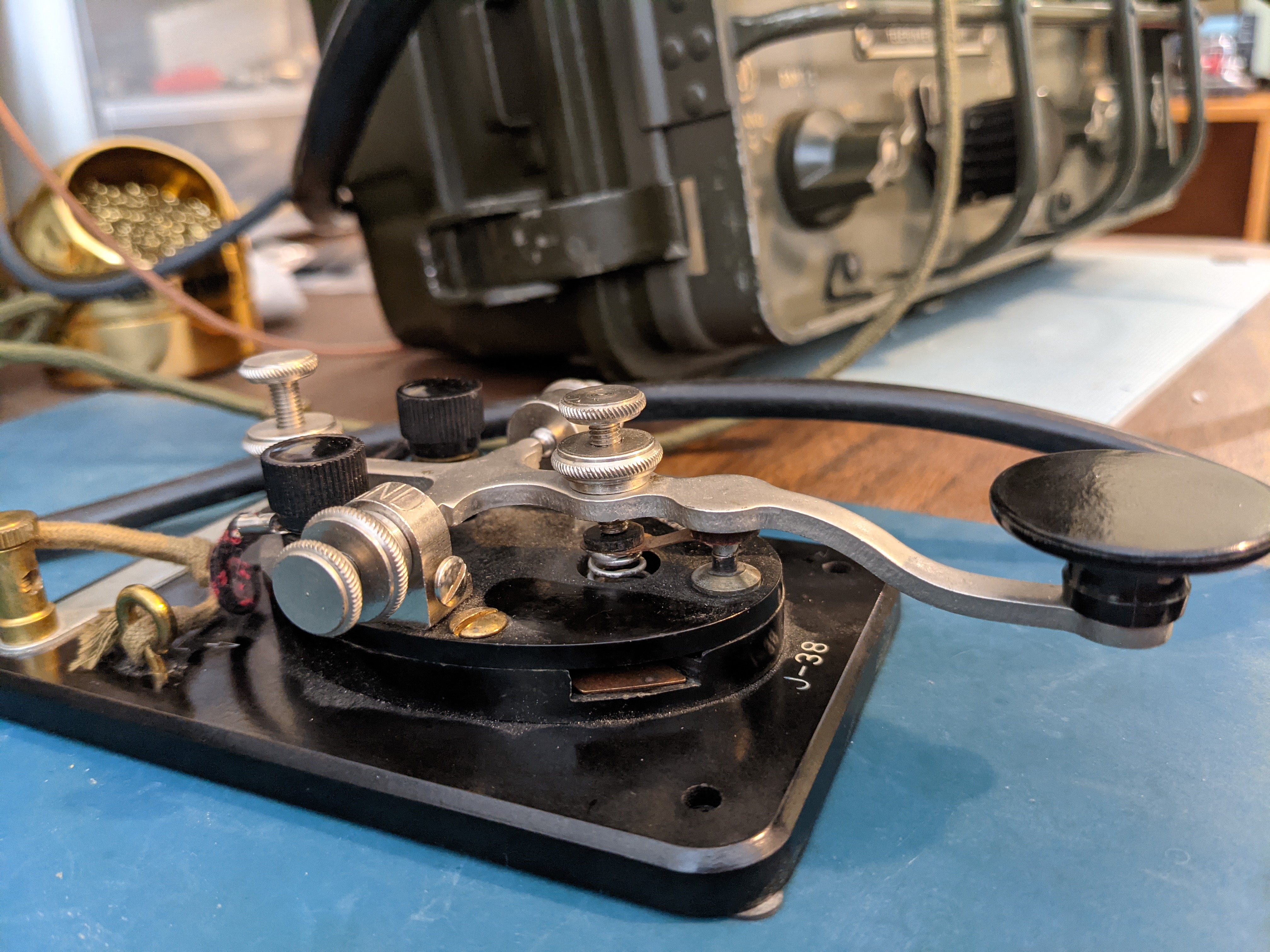
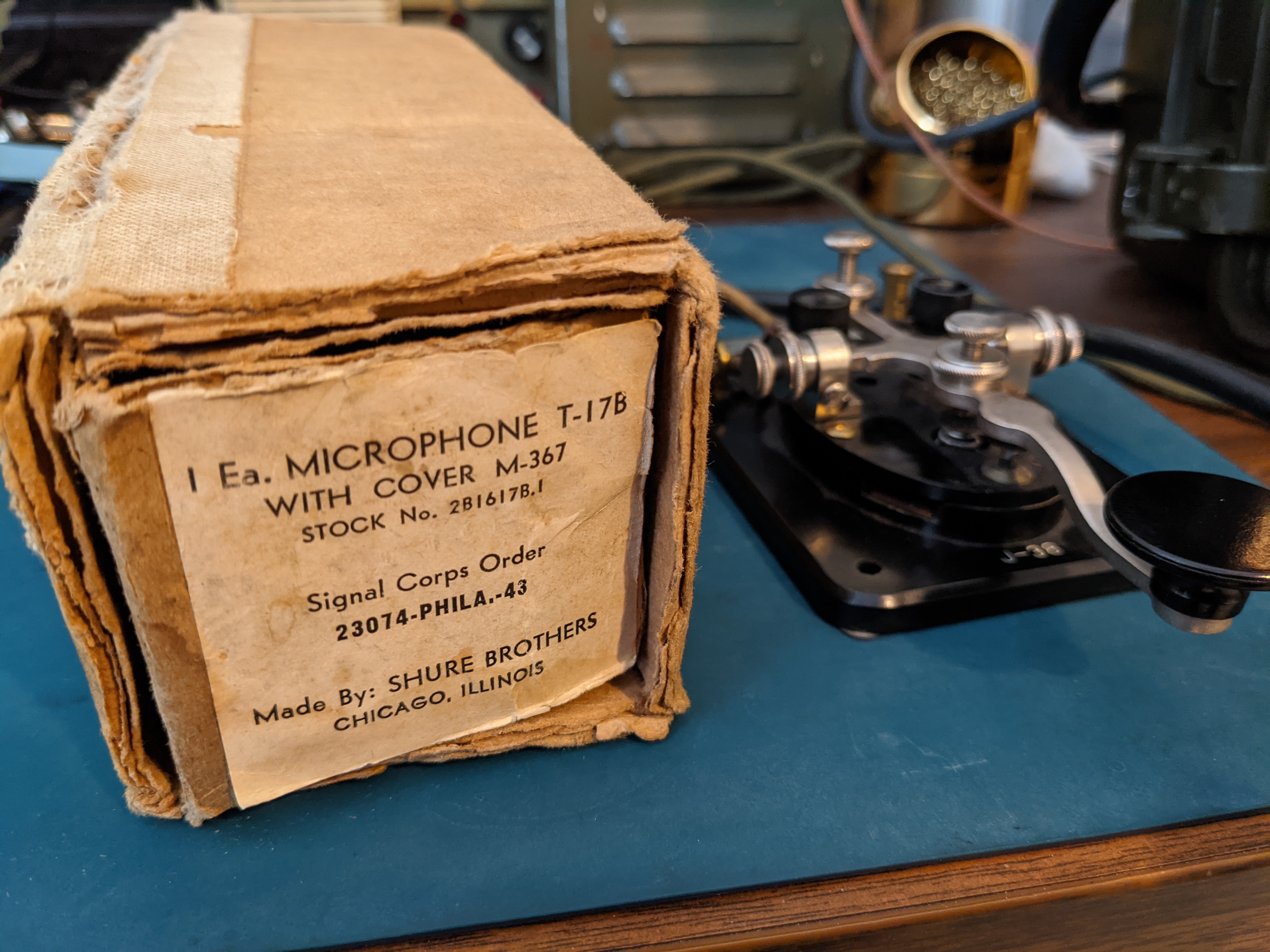
There's another bag (shown above) for carrying power supply cables, keys, hand mic, long wire and doublet antennas, external speaker, torture device headphones, torture device in-ear phones, as well as a box of spare tubes for the radio.
If you're traveling in a squad sized group, then many hands make light work, otherwise you're going to be making a lot of trips hauling your QRP rig up the hill.
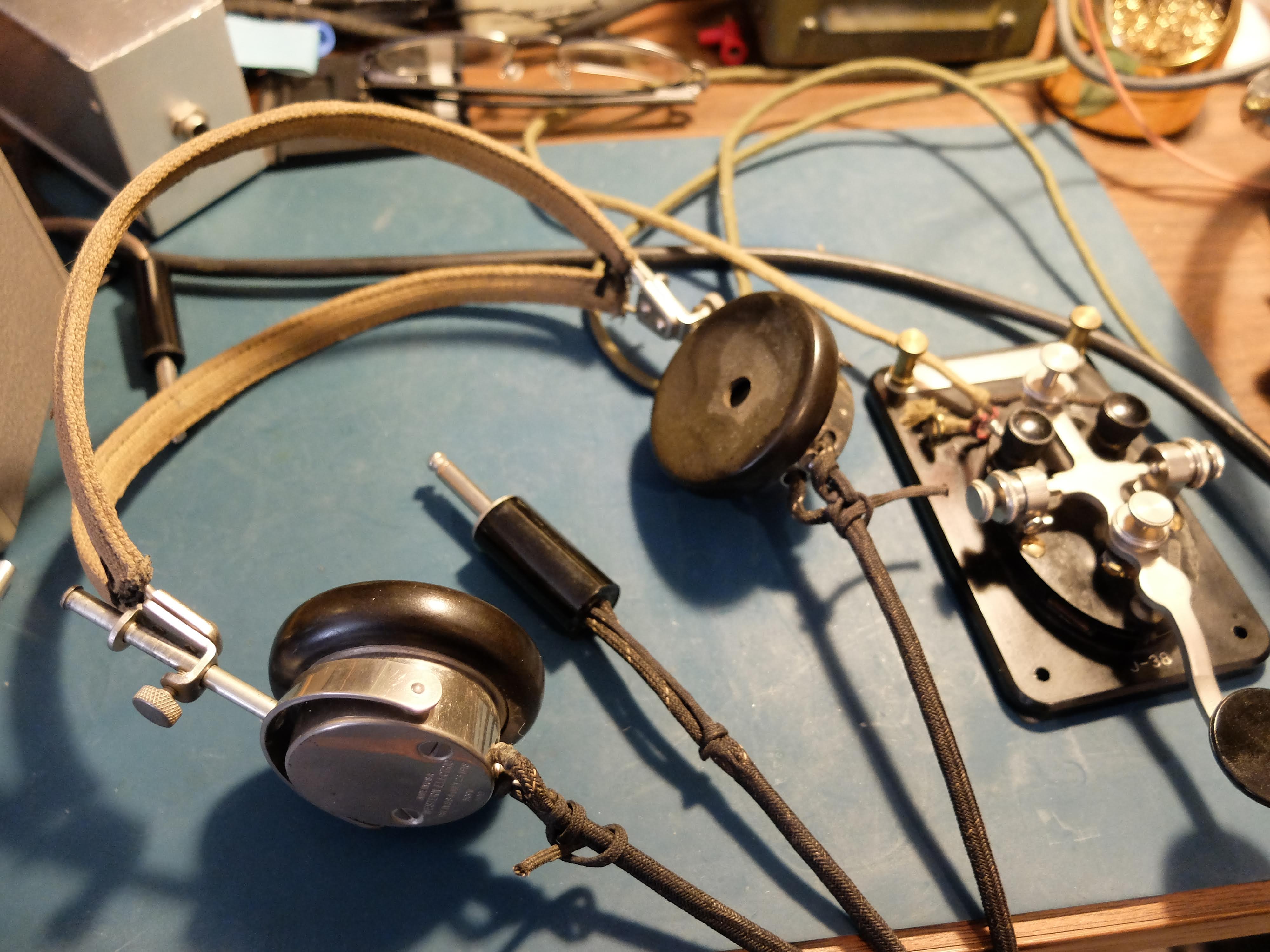
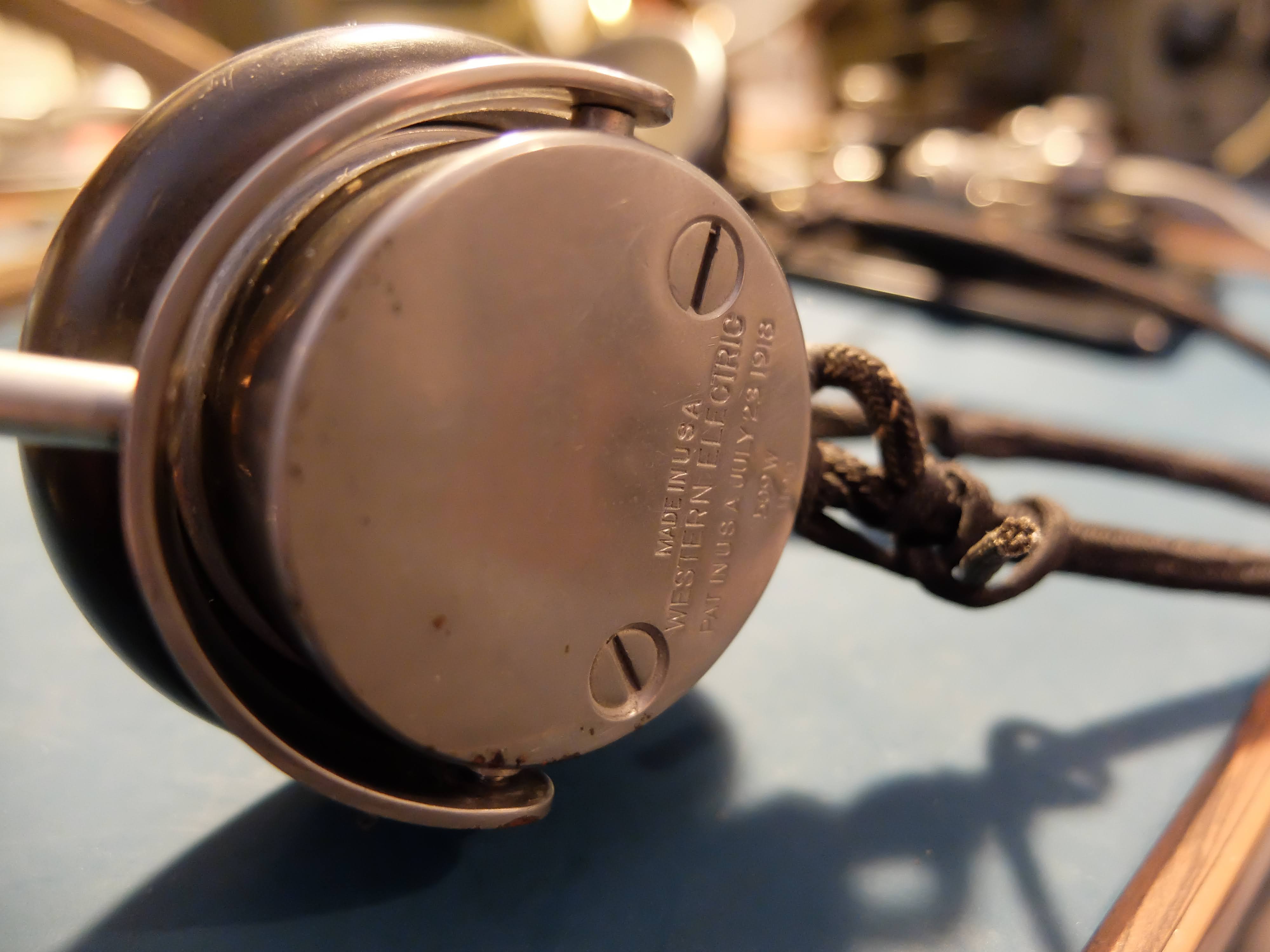
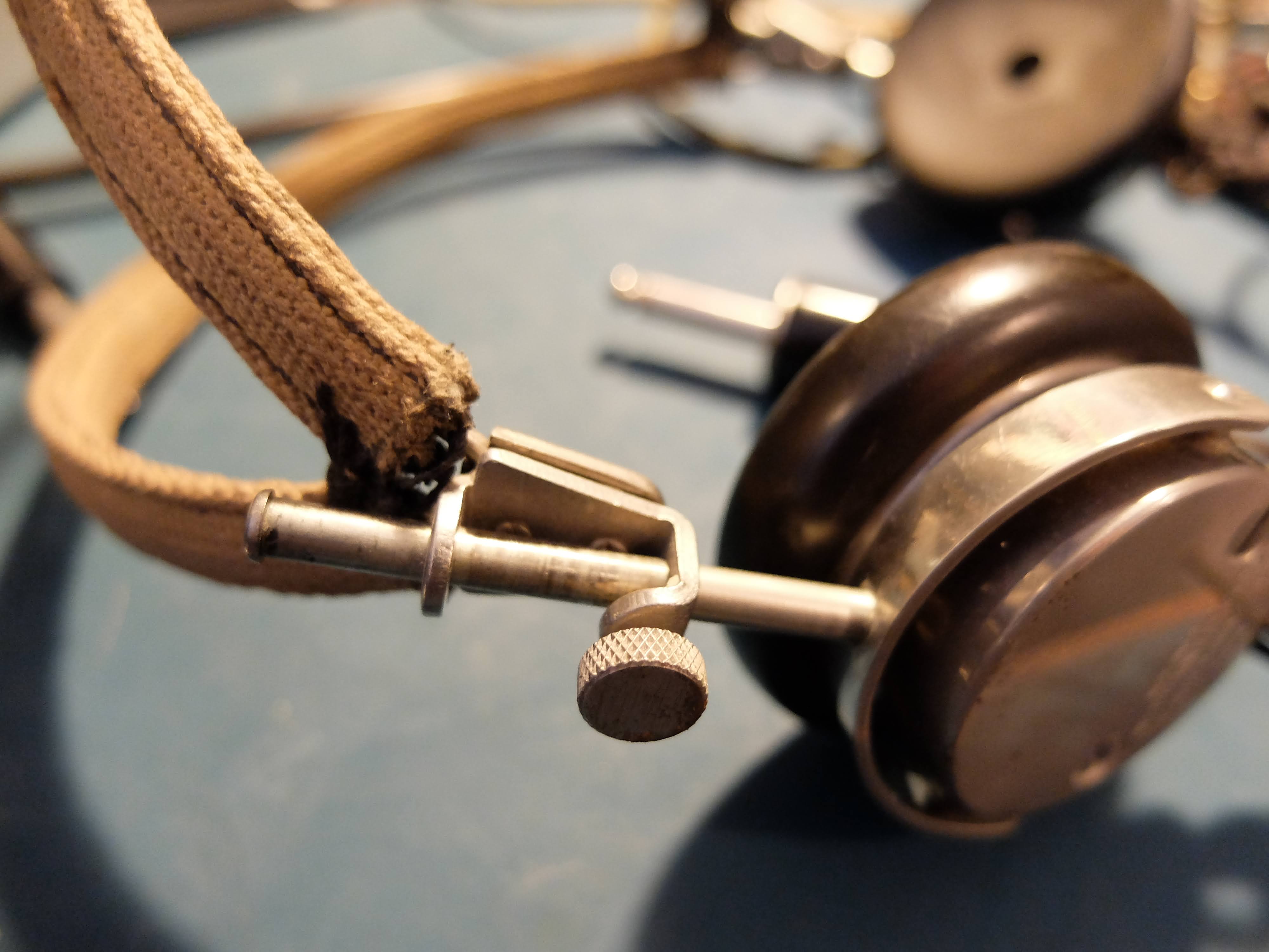
Headphones
These Western Electric headphones clamp tightly over your ears sealing out QRM and squeezing your head like a vice. After 10 minutes I was confessing to sins I'd never committed.
In order to use the headphones the RT/77 receiver must be removed from the case and an impedance switch on the back, changed from 4000 to 250 using a screwdriver. The ham I bought my set from had constructed a CW audio filter along with an impedance switch on an outboard box, that allowed the use of the headphones without switching the impedance on the receiver unit.
Homebuilt CW filter with impedance switch
Speaker
The external speaker is a rugged, high impedance device (4k Ohms), that after all these years can still output audio at high volumes without distortion. It has a built in thumbscrew clamp that allows it to be attached to vertical or horizontal objects.
Alternately, the thumbscrew can be used in combination with the vice-like headphones to extract information from a prisoner.
Antennas
The AN/GRC-9 comes with 3 antenna systems; a multiple section, whip vertical for quick field setup and mobile use, a long wire that can be quickly deployed in a fixed station as a sloper, and a doublet for best reception, transmission in a fixed location.
For testing purposes I have my radio hooked up to my 80m Windom, which it tunes very nicely on 80m, 60m, 40m and 10m bands.
When the weather warms a bit I will be taking the radio out for some portable use and I'll try it out with the antennas that are part of the AN/GRC-9 set.
Spares
As a military radio, it was expected that repairs should be performed in the field when possible. The radio shipped with spare tubes for the receiver-transmitter, as well as spare tubes and vibrators for the DY-88 power supply.
More to come
In the few days I've had the AN/GRC-9 the only problems I've encountered have been related to the old DY-88 power supply. Old vibrators cans are generally seized up, as was the case with mine. Eventually mine became un-stuck after repeated applications of power but there are some methods to restore truly frozen ones using AC current and light bulbs (see Notes section below).
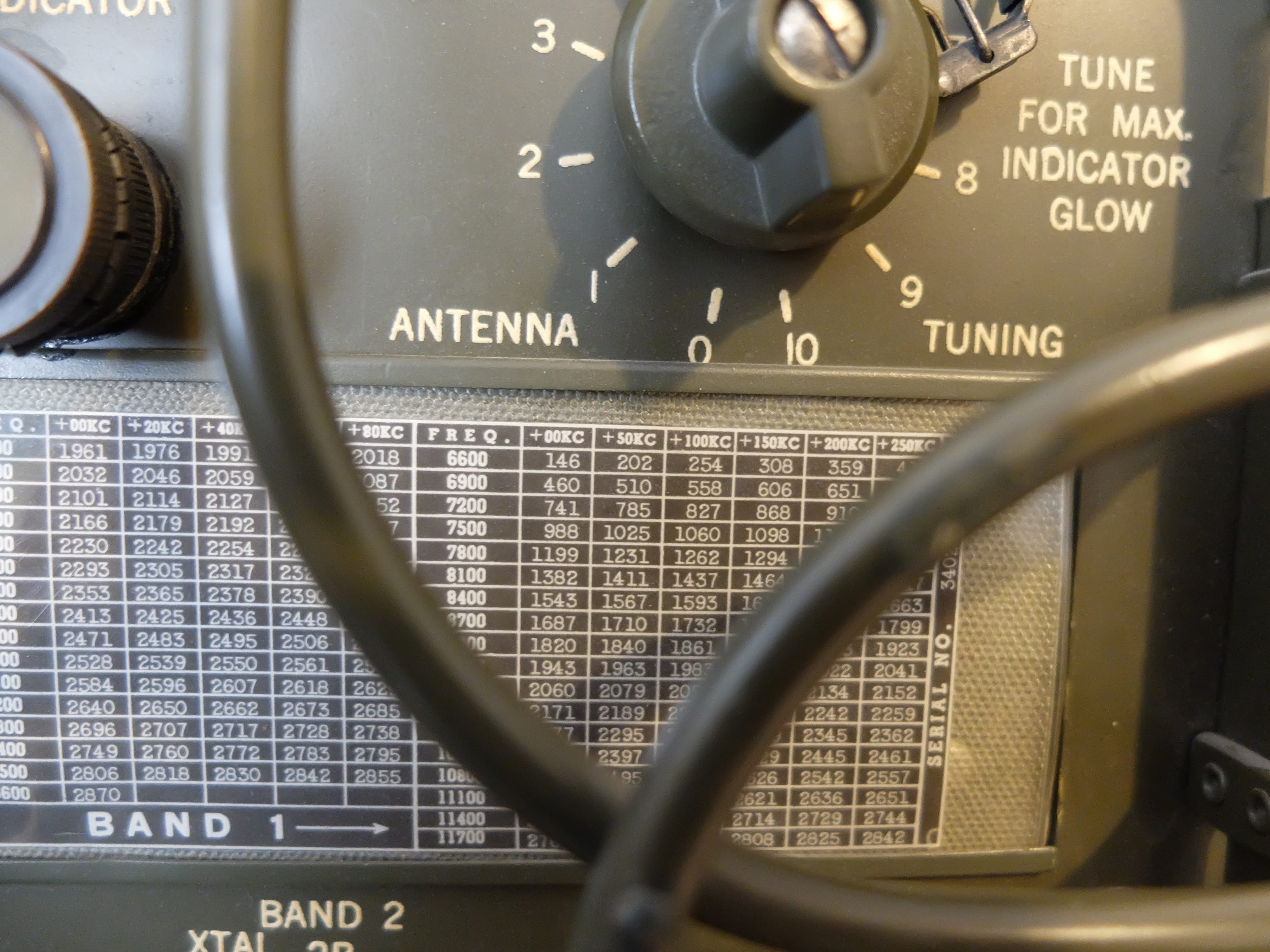
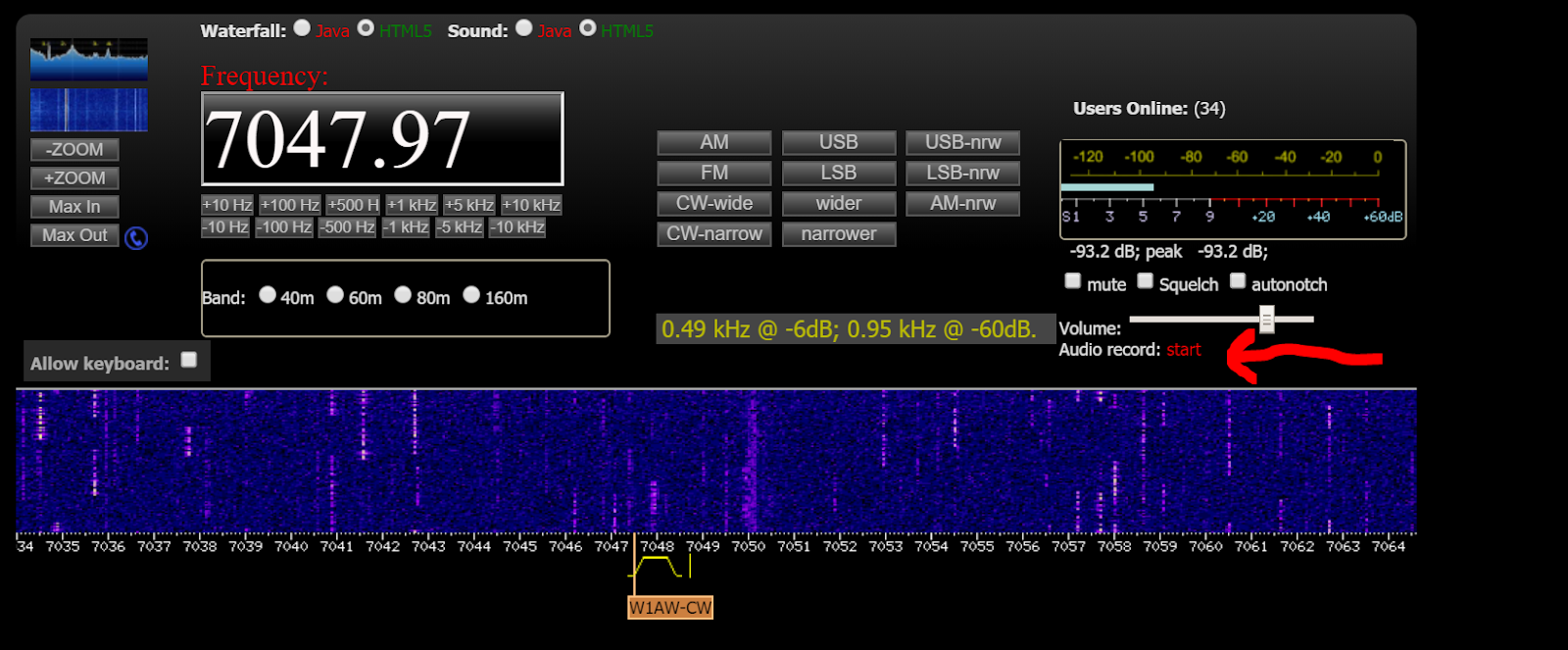
I've made about half a dozen contacts on the ham bands, including a 40m contact to a station in TX which is kinda DX for my locale. I've received nice signal reports. I've specifically asked stations about my "chirp" during QSOs and they've reported it as "not bad" and "charming". When operating from the VFO (master oscillator) rather than a crystal, the GRC-9 will "chirp". It was considered an acceptable design trade-off at the time. I've listened to the transmitter from a remote WebSDR station to hear the chirp for myself, and I agree that it isn't extreme and lends some character to the station. The unit does drift about 200 Hz during a QSO which I also think is quite acceptable for it's age. It's possible that if I spent more time in Send mode prior to a QSO to allow the transmitter tubes to warm up the drift might be lessened, but keeping the radio in Send mode puts quite a load on the power supply (both the 12v supplying the DY-88 and the human cranking the GN-58).
The RT-77 Telefunken receiver doesn't offer much in terms of selectivity and on a crowded band there's a lot of stations to contend with in the passband. The outboard CW filter deals with this nicely, but it is so narrow that when shifting from Send to Standby, the resulting frequency shift often throws the station I'm receiving out of the filter's passband, so that's a bit tricky.
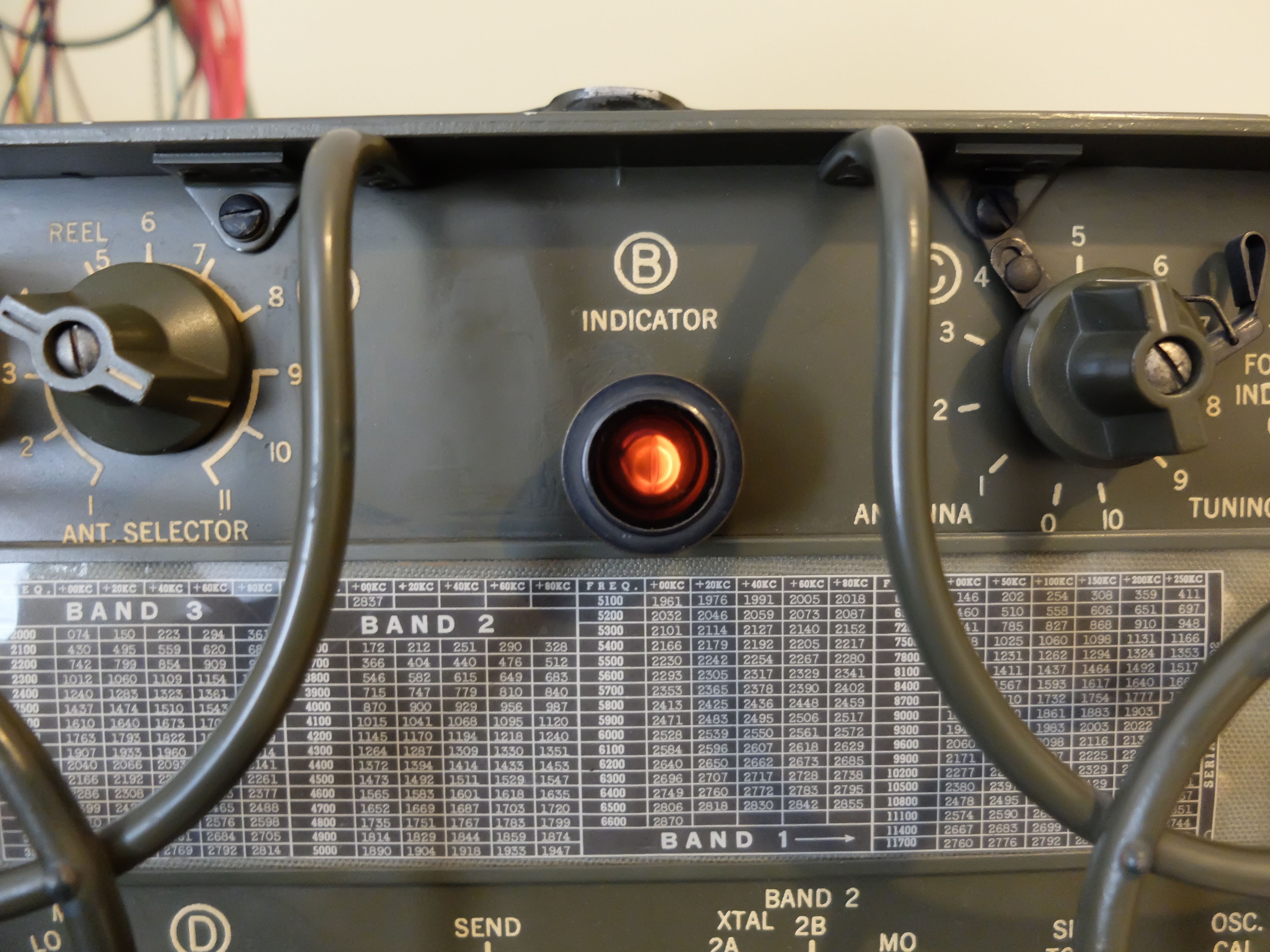
The receiver's tuning knob also is very coarse, in that fine adjustments are made by breathing on the knob. However it has zero backlash, which is amazing in a piece of equipment this old. The markings on the receiver are in 50 kHz intervals so the only way to really figure out where you are is to look at RBN for your spot.
50 kHz spacing when reading the frequency on the receiver Note the 7.2 is 7.200 MHz in the 40m band
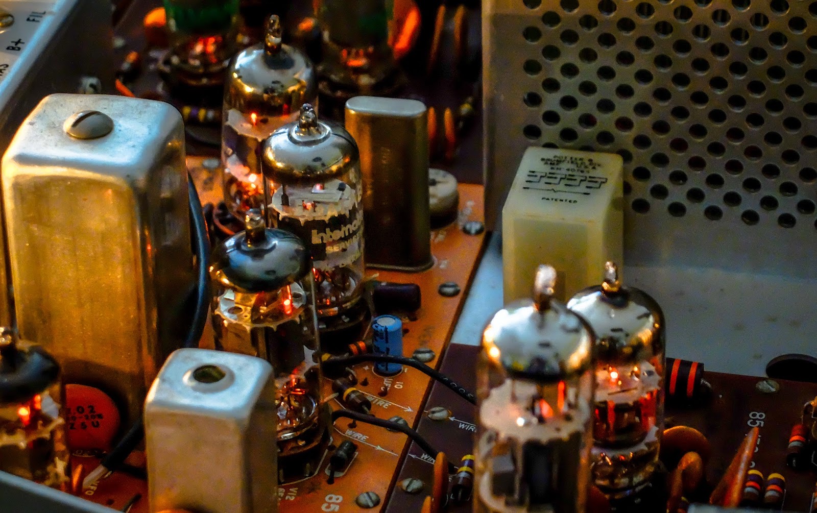
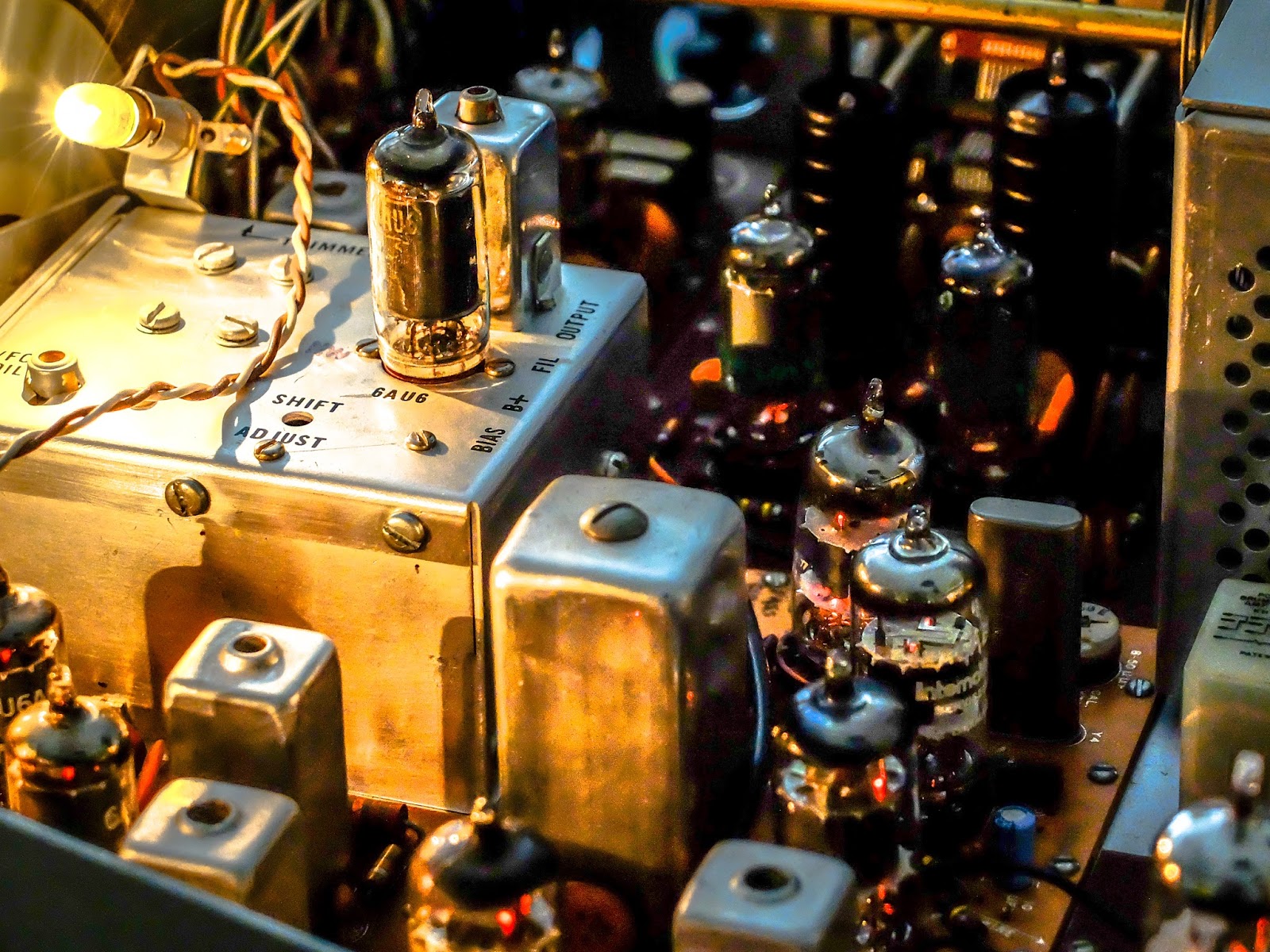
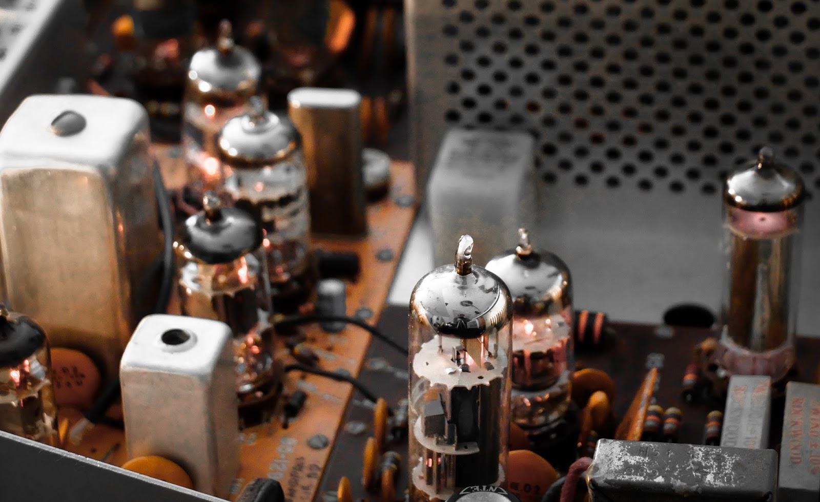
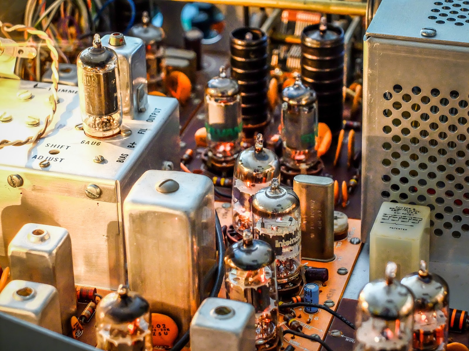
Images
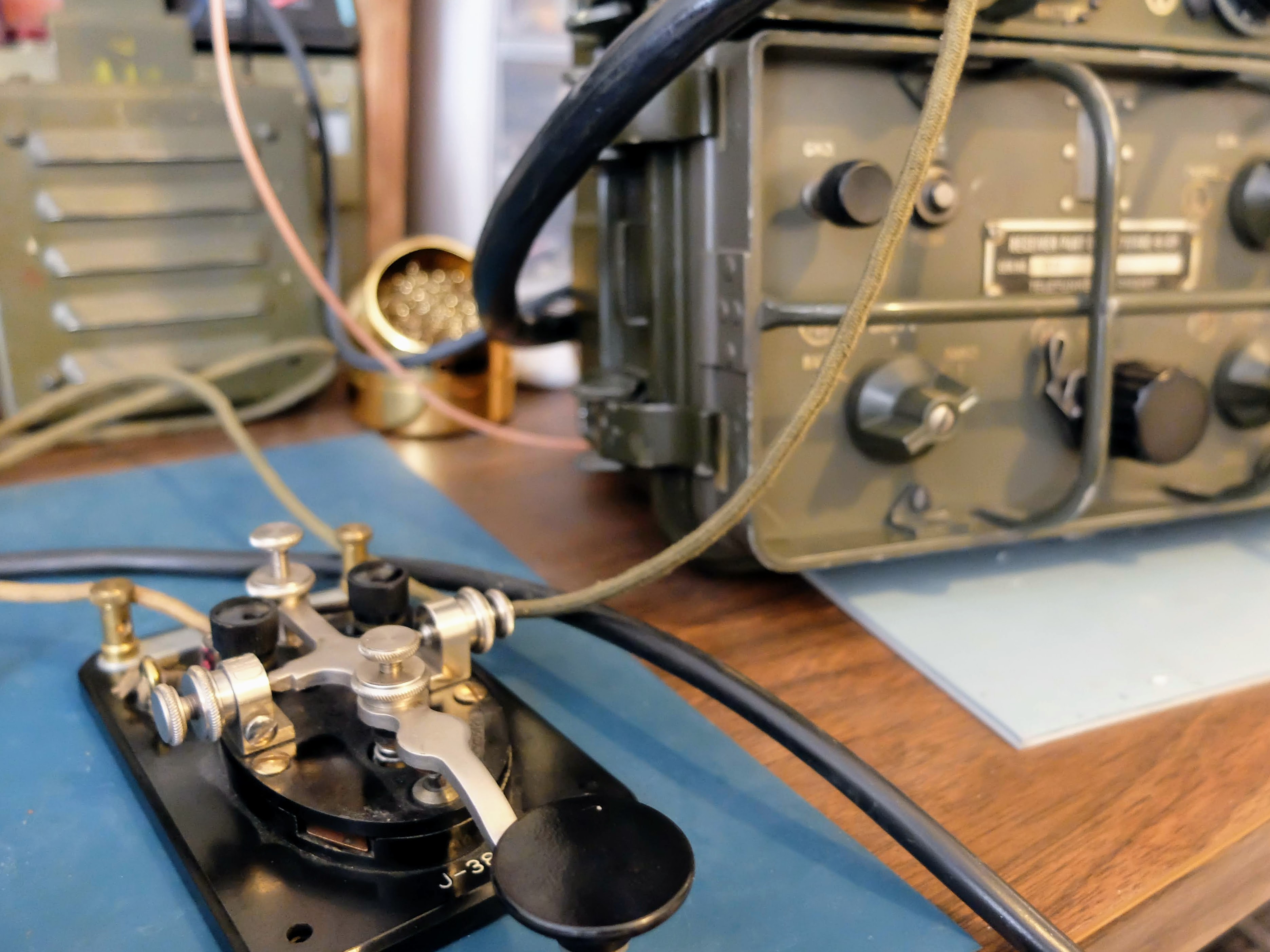
Enjoy the pictures of the AN/GRC-9
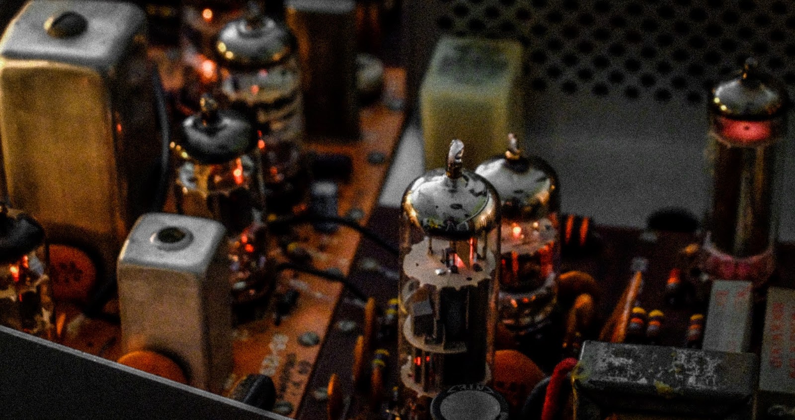
Phosphor glowing nicely on the GRC-9 As opposed to the degraded glow of the radium infused lettering on the RT-77 half
That's all for now
73
So go heavyweight for you QRP station to get your excercise.
DE AA4OO
Notes
Instructions for restoring a vibrator to operation
Instructions posted by:
Robert
Gunner
USN Retired
MVPA 9480
VB-1 and VB-7 are interchangable. I think I recall reading somewhere that VB-7 is a "lightweight" version of VB-1 but I won't swear to that.
The base is 4-pin, and the pin numbers are counted as on a vacuum tube with the same base. I wish I could post an image here without uploading it somewhere but if it's possible I've not figured out how to do it. The pins count clockwise from 1 to 4 looking at the bottom of the vibrator or the wiring side of the socket. The two large pins are 4 and 1 and the two small ones are 2 and 3.
There are two basic types of vibrators, called Series and Shunt. The Series type has a contact in series with the coil. VB-1, 7 and 16 are all Series types. I'll skip the Shunt type for now.
Pin 1 is common. Pin 4 is coil. Pin 2 is the NO (Normally Open) switching contact and Pin 3 is NC (Normally Closed). To test a VB-1/7, use an ohmmeter to check continuity from 1 to 4. If the reading is infinity, the coil could be open but this seldom happens. The problem is probably the vibrator contact. If the reading is a few ohms, connect +6 VDC to Pin 4 and -6 VDC to Pin 1. The vibrator should run. If it doesn't, most likely the contact is welded. About the only solution is to open up the vibrator, unstick the contact and try to burnish the burn marks out of the contact.
If the vibrator does run, go to the end of this screed and do the final test.
If the reading is infinity, here's how to use the two or three lamps to (usually) fix the vibrator. SAFETY NOTE: bear in mind you are dealing with either 120 or 220 VAC. If you jury rig the hookup, do all of your connections and disconnections with the "rig" not connected to the AC line. In other words, don't touch anything except the plug on the line cord or (if you go to that much trouble) the ON-OFF switch when the line cord is plugged in.
Connect the hot side of the AC line cord to one side of both lamps. Connect the ground side of the AC line cord to Pin 1 of the vibrator (or socket if you use one). Connect the other side of one of the lamps to Pin 4 and the other lamp to Pins 3 and 2. If you splurge and use three lamps, connect the "cold" side of the second and third lamps to Pins 2 and 3 respectively.
Check all the wiring and when satisfied all is OK, plug in the line cord. Probably nothing will happen immediately. Within a few minutes to a few hours lamp 1 should begin flickering and you should hear the vibrator hum. Run the test until the second lamp begins to flicker or until both the 2nd and 3rd lamps flicker.
If you are only using two lamps, when the 2nd lamp begins to flicker, wait 1 or 2 minutes then remove power (unplug the line cord). Connect the 2nd lamp only to Pin 2 and plug in the line cord. If the 2nd lamp flickers, remove power, move the 2nd lamp connection to Pin 3 and apply power. In either case (with the 2nd lamp now connected to pin 2 or 3 only), let the test run until the 2nd lamp again flickers.
For a final test, connect one lamp to Pin 2 and one to Pin 3. Connect 6 VDC to Pins 4 and 1. With the vibrator vibrating apply power to the two lamps. They should flicker alternately. Note that for this test, either use a 6 volt battery or a 6 VDC supply with both outputs not grounded. I wouldn't try to use the battery in the Jeep just in case you mis-identify which side of the line cord is grounded and which is hot.
Although a vibrator that is going to be fixed by this procedure will usually begin to work after say no more than half an hour, I have seen it take several hours. So if I have one that didn't start working fairly quickly, I'll let the test run up to about 8 hours max (or overnight) before giving up.
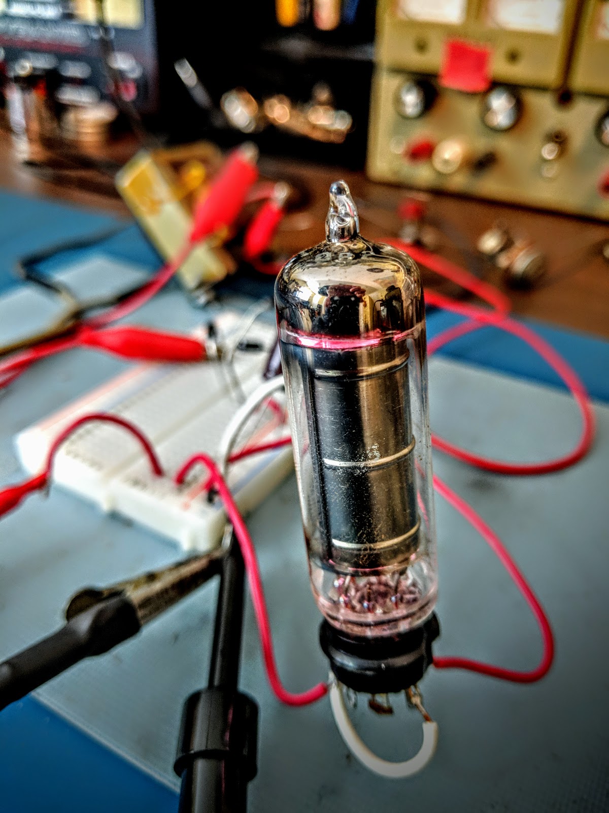
Building a regenerative tube receiver seems to have been a rite of passage for all hams of yesteryear. Although I built one from a kit (4-States QRP) as my first electronics project a couple years ago I thought I'd go for the real deal and build a vacuum tube regen receiver.
I'm building a design based around the 6SN7 tube. While I'm collecting parts and still locating a suitable chassis I decided to build a regulated power supply from the parts I have. Anyone familiar with electronics could probably whip this together in no time, but being the electronics newbie that I am, it is a slow process.
I'm using a transformer from a 1950's Heathkit VTVM V-7 that I parted out. It supplies the 6.3V filament voltage from one set of windings (yellow wires) those tested good. But the HV was an unknown as it was only half wave rectified when the transformer was used in the meter. That meter's rectifier and power cap had gone bad so I didn't know what condition the HV side of the transformer.
Breadboarded using a full wave rectifier created with 4 diodes, buffered by a 22uF electrolytic and a 10k resistor, I saw 189 volts, with no-load out of the high voltage side of the transformer. The amount of current the transformer could provide was still an unknown. I tested temporarily with a 2.5kOhm high wattage resistor and saw 56ma of current provided with a voltage sag down to 130V but the core of the transistor started heating up. Within half an hour it was over 120F so I discontinued that load test.
Fortunately, the regen circuit uses a ridiculously small amount of current for B+; about 4 to 5mA. Although I will likely change the audio side of the tube to deliver enough current for a speaker rather than the high impedance headphones in the current design, which may potentially double that to 10ma. For the first incarnation I'll stick with high-impedance headphones.
The regen power supply requirements called for 6.3V@0.5A and 90V@4mA B+. The B+ voltage was based on using 10x 9V batteries and it stated that voltage wasn't critical but shouldn't fall much below 90V, going 12% above 90V should be OK.
Generally batteries are used with regenerative receivers because they are so sensitive to power supply noise, but I wanted to give the power supply a shot first and if it proves too noisy I can fall back to battery power for the B+ and just use the filament voltage provided by this transformer.
Since I have a OB2 voltage regulation tube I want to use. The OB2 regulates at 108V so that's what I'm going with. An OB3 would regulate at 90V, but I don't have one of those.
OB2 in action... Glow baby, Glow!
Calculating the resistor drop
A voltage regulating tube like a OB2 ionizes gas to maintain the voltage at the tube's specification. In the case of an OB2 it tries to maintain voltage at 108V. It requires a starting voltage higher than what it will regulate to, but ultimately can only dissipate so much current as it drops voltage. So, a resistor must be put in series ahead of the VR tube to limit the current it will have to dissipate. The resistor must be able to handle the current flowing through it, so that must be calculated as well.
The calculation for the dropping resistor resistance is:
Rdrop = (Vs - Vreg) / (Ireg + Isupply)
So, in my case:
Voltage supply (Vs) = 189V
voltage regulation (Vreg) = 108V
regulator current (Ireg) the OB2 requires 5mA to do its job = 5mA
supply current (Isupply) the actual current required by the 6SN7 up to ~ 5mA
So, (189V - 108V) / (0.005A + 0.005A) comes out to a resistor value of 10,100 ohms. 10k is the closest standard size resistor and at 108V it should be able to dissipate 1.166 watts. So I'll need a 10k 2-watt resistor.
Parts is parts
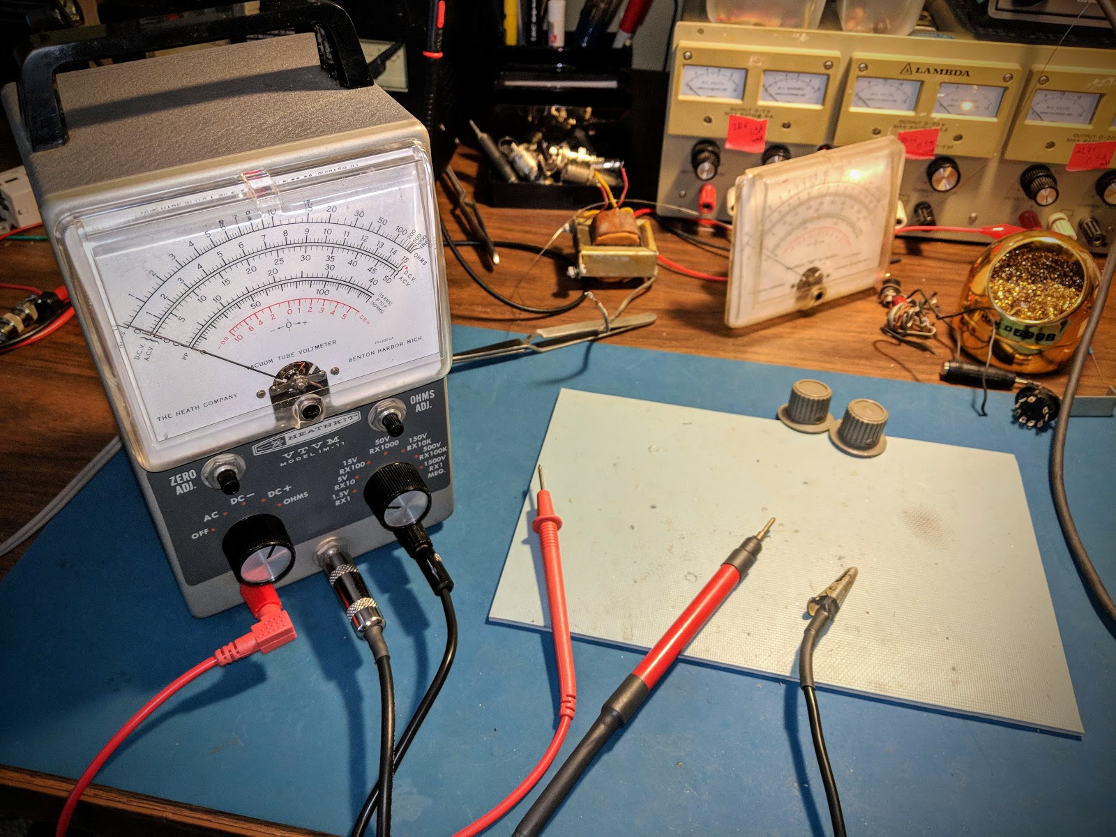
Running the regulated power supply with a 10k Rdrop resistor for a few hours showed the transformer stabilize at 92F degrees at 70F amb. I was using a separate 27k 2-watt resistor to simulate the ~4mA load that the receiver will draw at 108V.
As you can see on the newly restored, trusty Heathkit VTVM; the voltage was holding steady around 108V. With that little current, the OB2 is not visibly glowing but with the lights out the violet colored ionization is visible.
Summary
I'm going to order a larger filter capacitor. The only one I had to test with was 22uF 360V and I'd like to use higher capacitance value of 47uF with a more appropriate voltage rating of 250V. I will also be adding 0.01uF caps at the input and output of the filter capacitor and I may add a 0.01uF across the OB2 pins 1/7 to further attenuate any RF noise.
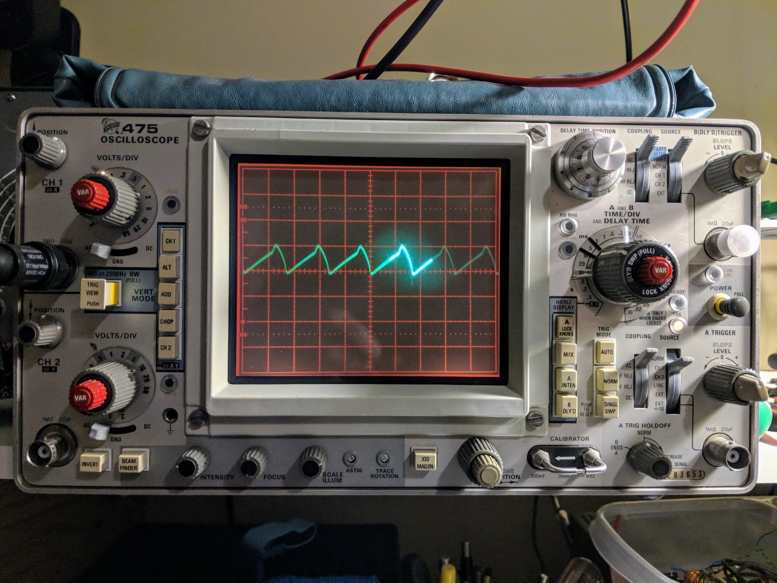
With the current values I'm seeing 50mA ripple on my regulated voltage.
A bit over 50mA ripple
After I get the new capacitor and get the 0.01uF caps in play to filter out noise, I'll hook it up to the oscilloscope to check for ripple. I'll update the post at that time.
That's all for now....
So lower your power the old fashioned way, using a voltage regulator tube.
I recently got a taste for restoring and using vintage vacuum tube radio equipment. Using equipment that requires 800+ volts for making QRP transmissions is counter-intuitive to the spirit of QRP ham radio, but it's part of my journey as a ham, so I'm writing about it. Bear with me. Once I receive a near fatal shock I'm sure I'll move back to 12v powered equipment again.
Until then...
One of the first issues I ran into while testing the power supplies I restored for my vintage gear was how to measure voltages beyond the range of my digital multi-meter. Most consumer grade digital multi-meters (DMMs) can only measure up to 500 volts then display an error, or stop working altogether. Previously, I was able to measure voltages over 500V by making a voltage divider out of two 100k 1w resistors and taking my measurement from the middle of the two resistors, but it was precarious in use and added even more danger when working with this old equipment.
I'd looked at getting a DMM capable of measuring high voltage, but the recommended ones, like a Tenma 72-1055 Benchtop Digital Multimeter, start around $100. Used Fluke meters are even pricier. I'm sure buying a more professional DMM would be a wise investment. As I've evidenced many times; wisdom is omitted from my DNA.
So what did hams of yesteryear use?
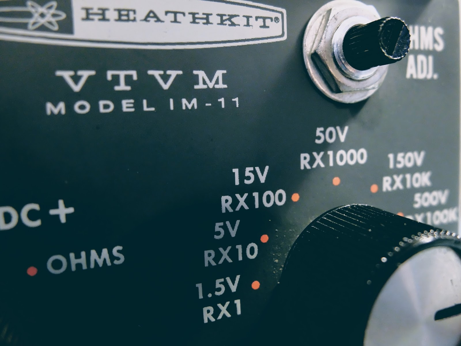
Behold...Vacuum Tube Volt Meter
Vacuum Tube Volt Meter
This Heathkit VTVM model IM-11 was available at my local Hamfest (Rarsfest) for 5 dollars.
Debugging
Five dollars is not a princely sum, but as with most things purchased from a hamfest, it required some attention.
The 55 year old 16uFd@150V paper, electrolytic power filter capacitor was likely a ticking time bomb so I replaced it with a modern capacitor for safety concerns. The closest one I had was a 33uFd@160V radial electrolytic. I don't think double the capacitance will be a problem for a filter capacitor, it will just make the transformer work a little harder when it's first turned on. I calculated the initial charge time and it's 393ms vs 190ms for the original cap. I think the 10k resistor and transformer can handle the extra 200ms heavy load on power up.
A few wires inside the meter had come loose from some very sparse solder points and a one intermittent connection in the range switch was especially troublesome to track down.
The biggest mystery to solve was oversensitive resistance readings in the Ohms mode. I replaced the C-cell battery in the battery cup and while I had it out I glanced at the + connection for the battery in the cup. I appeared to have oxidized at some point in the past and was discolored. I scraped it off until I saw shiny bits and thought all was good. I spent more time tracing the circuit and thought I had a problem with the switch itself or the 9x resistors in the range circuit, as suggested in the troubleshooting section of the manual. The problem turned out to be that oxidized bolt head that formed the positive battery connection in the battery cup. Scraping it had not provided electrical contact. In fact, when I removed the bolt (after having to disassemble the circuit board from the meter for the 2nd time), I filed down the head of the bolt and could find no conductive metal left. I'm guessing that a former leaky battery had converted the entire head of the bolt to a very hard, yet non-conductive material. I've never seen anything like it before and it proved to be a useful lesson.
I had to find a replacement bolt and that lead to working on my lawn mower and then mowing the yard... not sure how that progression occurred... Eventually I got the new bolt in the cup, the circuit board re-installed. Ohms tested accurately, put it all back together and noticed the #50 pilot lamp had stopped working (sigh). I removed the innards from the case one more time and got the pilot bulb settled (I think it's required to balance the filament circuit). While I had it apart for the umpteenth time, I decided to reconnect the 1/4" plug that a former owner had disconnected while keeping their original modification allowing 1 mega-ohm to be switched in for the outermost probe when DC functions are selected but switched out when AC or Ohm functions are chosen. I wanted to allow use of an original VTVM probe used in the 1/4" plug with its built-in 1 mega-ohm resistor.
Whew!
All-in-all, I probably spent 8 hours getting all the functions on my $5.00 meter to work, replacing old parts, undoing mods and aligning it for proper DC and AC readings. It's a good thing I don't count my time in the cost of these projects, otherwise I could have purchased a couple Fluke meters for the cost of my time.
What's the fun in buying something that works right the first time when you get it home, huh? Are we hams, capable of solving problems, or appliance users? Actually, it would have been nice if it worked without new parts and repairs, but I digress.
Back to the story
This meter can measure up to 1500 Volts 🗲
The main reason I purchased this is to measure the high voltage in my tube equipment power supplies and 1500 VDC should just about cover it.
Although this meter uses a C-cell battery for measuring resistance, it runs off service mains to power the tubes which control the meter circuitry, so it must be plugged in to be used.
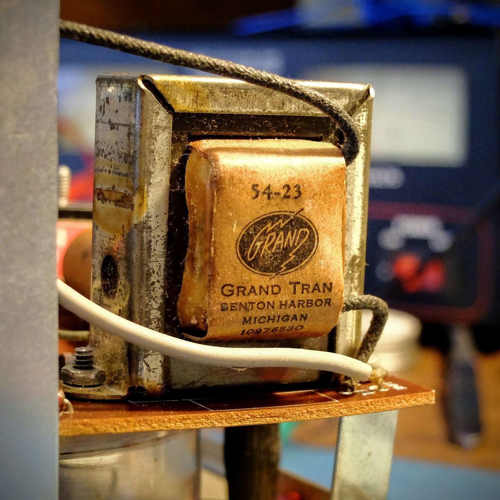
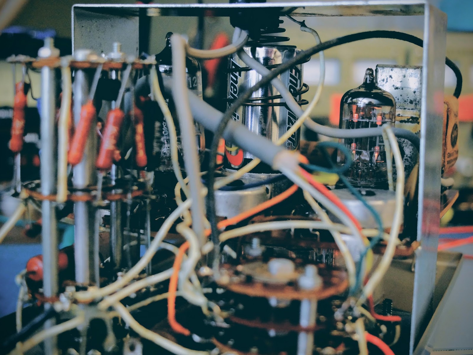
I love the look of its old "Gran Tran" power transformer inside the VTVM. They just don't make'em like they used to.
Wiring, lots of wiring
This model was made by Heathkit, from 1961 through 1968, and used typical point to point wiring of the time, making circuit tracing loads of fun.
Point to point wiring makes for interesting circuit tracing
Shiver me timbers, it's got decks
Fun fact: When reading the schematic it will refer to "decks". A "deck" is a wafer section. When there are stacked sections as there are in the function and range controls the "front deck" is the one closest to the knob (front of the case) and the "rear deck" is the one furthest away, or in the case of working on it, the one closest to you. When there are more than two decks, as is the case with the range control, it will refer to the "second deck". As you'll likely guess by now, that is the second "deck" or wafer disc from the front of the instrument.
It also refers to "front half" and "rear half". The "half" is referring to a side of the deck, so in the case of "front half" it refers to the side of a particular deck facing the front of the instrument, while the "rear half" is the side of a deck facing back (or toward you).
Clever voltage divider circuitry, what could possibly go wrong in this triple stack of wafer switches?
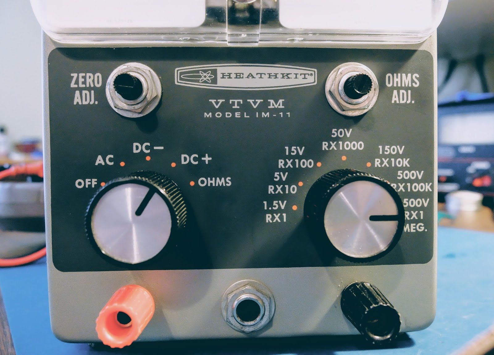
The left knob controls on/off and meter functions while the right knob controls the rather elegant voltage divider.
A knob for every function and a function for every knob. NOTE: do not plug your headphones into the 1/4" jack on the front unless you want to experiment with personal electro-shock therapy. Better, yet, don't plug your headphones in there.
Not clearly shown in this photo, voltage divisions up to 1500 volts supported
"...Weighed in the scales and found wanting"
Ok, how many of you understand that completely unrelated biblical reference?
I haven't used a meter like this since I used to plan my VFR flights using an E6B. My modern, digital multi-meter is fairly idiot proof in terms of reading the results. My DMM auto-ranges and displays the correct unit of measure along with the reading on its display. It works well for a dummy like me.
A VTVM on the other hand, has a number of scales that must be interpreted based on whether you are reading DC, AC or Ohms. Additionally, you have to pay attention to the range chosen.
Choose a reading... any reading, just use the correct scale
Note: the needle isn't at zero in this photo because I had just plugged it in before taking the picture and the tubes hadn't warmed up. Ah, the joys of vacuum tube powered equipment
The voltage markings for the range switch refer to the full scale reading. Resistance is the top scale, but let's ignore that because we're talking about measuring voltage... The second scale from the top is Voltage. Even though it appears to refer to DC for the numbers on the top and AC for the numbers on the bottom of that second scale that's not what's going on. The second scale is for both DC and AC. The numbers on the top are when you are using a range that is a multiple of 15, such as 0-1.5V 0-15V 0-150V 0-1500V. The numbers on the bottom of that scale are for the ranges using a multiple of 5, such as 0-5V 0-50V 0-500V. Clever eh?
You have to do a bit of math. For example, if you if you're using the 1.5V range take your reading and move the decimal place one to the left. So, a reading of 8 would represent 0.8V in the 1.5V range, while it would actually represent 8V in the 0-15V range and 80V in the 0-150V range, etc. See, hams were smarter in the 1960s.
Always start with a range larger than what you expect the voltage to be and reduce the range for a more accurate reading if it occurs in the lower 3rd of the range. The voltage divider set by the range knob is protecting the circuits so if you have it in too low a range and apply high voltage, bad things will likely occur.
Old school needle gauge. There's a lot going on behind that needle. It operates very smoothly.
Sporting some temporary probe hookups
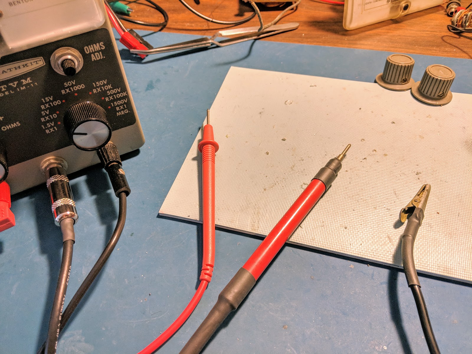
Making probes
This meter did not come with probes. I bought another older VTVM pretty cheap, for parts from a famous auction site because it was advertised as having a full compliment of probes, but alas, they were not usable. Even the 1/4" plug from those probes was a bust. However they did come with rebuildable probe "ends"
I used a RG-58 cable as the high voltage DC wire using only the center conductor and grounding the shield even though it is not used as the ground return. I also placed a 1/4 watt 1 mega-ohm resistor at the tip of the probe to limit any current through the probe cable. That cable terminates in the 1/4" plug and is wired such that it is out of the circuit in the Ohms position. I secured the cable into the probe body with some glue and used two layers of shrink wrap as a strain relief. I also put some shrink wrap near the probe tip as a bit of extra insurance.
I used a spare DMM cable for the outer positive banana plug feed used by the AC and OHMS circuit and made a heavily insulated cable with an alligator clip for the ground probe that goes to the other banana plug.
The outer probes are used for measuring resistance, AC and low volage DC. The center probe is used only for high voltage DC positive. Both positive probes would not be connected at the same time (as they are in the image below), and would present a shock risk if they were both connected when measuring voltage.
Summary
If you need a way to measure high voltage or are looking for a really eccentric meter to make common measurements harder than they should be get one of these VTVMs. They seem to be commonly available at hamfests and on famous auction sites for under $10.
Dazzle your friends next time they ask you to measure something for them, by whipping this not-so-little-puppy out of your back pocket and powering it up. As you're making your measurements quietly repeat "Mmmm, yes. Mmmm yes, I see now". They'll have no idea what you're referring to and be quite impressed.
That's all for now...
So lower your power and measure it with the low-range on your snazzy Vacuum Tube Volt Meter
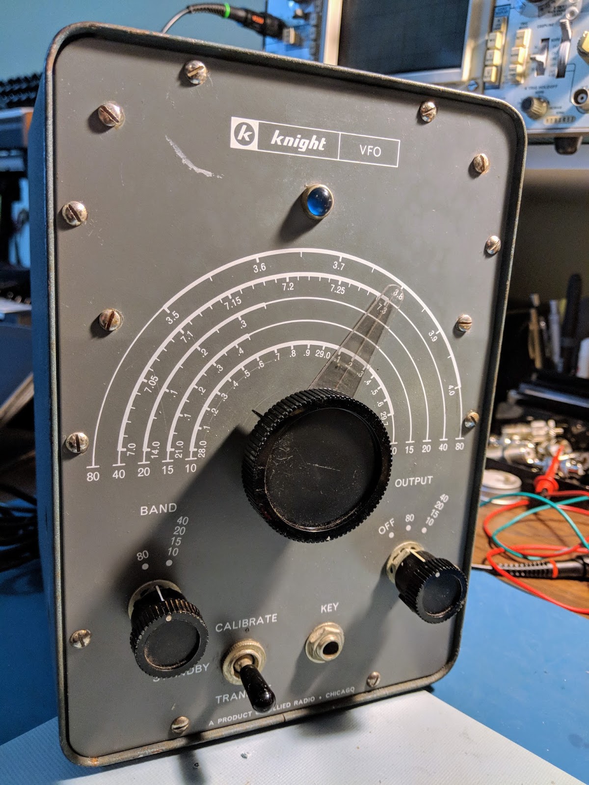
Late night eBay surfing, and poor judgement led me to bid on a Knight V-44... and unfortunately won it...
Note to self: Never browse eBay just before you go to sleep
The 1955 remote VFO was unique because it had a built-in power supply. It's also interesting that its base oscillation frequency is in the 160m band. Using harmonics from the base frequency means it doubles for each subsequent band (x2 for 80m, x4 for 40m, etc.) That doubling means it also multiplies the drift. Specified drift is 300Hz an hour. That doesn't sound too bad, but multiply that by x6 up in the 10m band and holy-smokes, it's drifting 1800Hz an hour.
That's gonna make operating CW like a game of chase, or hide and seek after every exchange.
This is gonna be fun.
Surprisingly the big dial is actually operating the variable cap through a reduction gear and it's very smooth
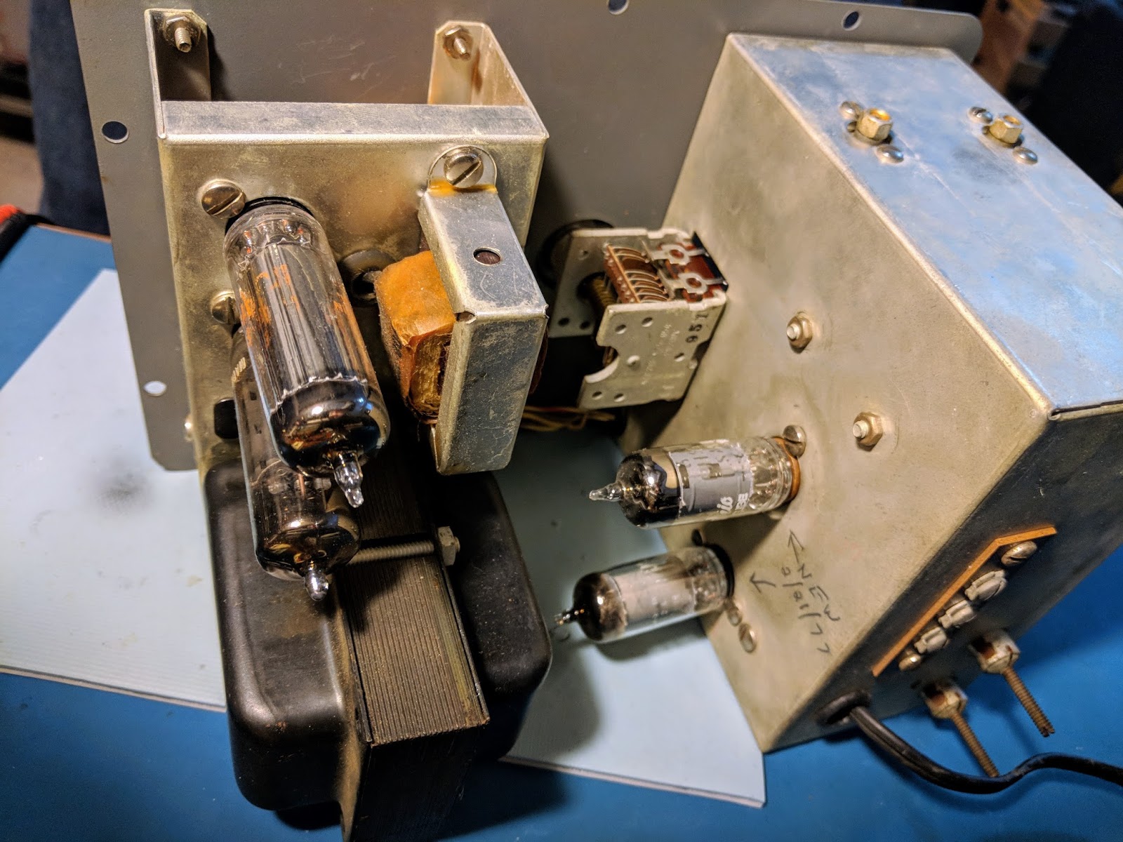
Uses 4 tubes. Power supply up top, VFO circuits in the bottom to minimize impact of heat from the PS.
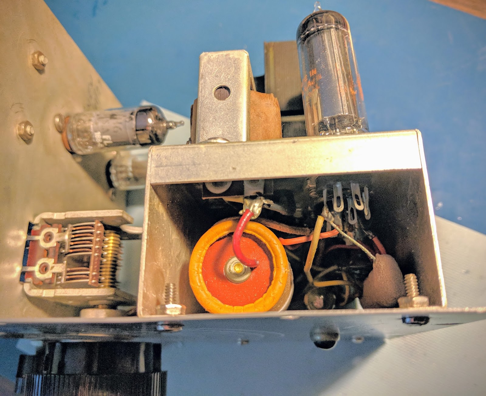
Power supply
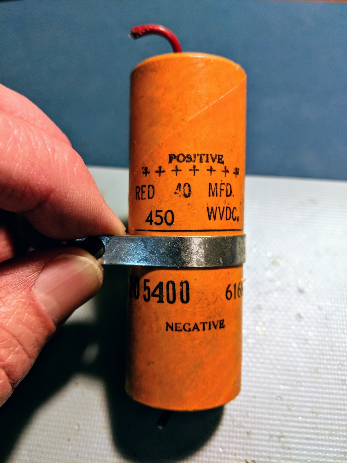
old electrolytic power filter cap must be replaced
10k 7watt resistor had failed
Replacement bits
The 450v electrolytic cap must be replaced for safety reasons. All the other components measured within 10% of specifications except for the 10k 7w resistor connected to the OA2 tube. It had gone up into mega ohms of resistance, which is likely when the VFO was taken out of use.
Handwritten notes inside the chassis indicated the VFO tubes had been replaced in 1977. Until I get the replacement parts for the power supply I won't know the condition of the tubes.
Plans
I plan on using this with a Homebrew transmitter that I may build sometime this summer.
Surprisingly, it outputs 10 volts of signal, so I may also build an output filter and use it as a QRPp transmitter on its own.
The possibilities are endless.
Update 3/21
Repaired
The replacement parts arrived from Mouser... A 500v 47uF electrolytic capacitor and a 10k Ohm 7-watt resistor. The new high wattage resistor is tiny compared to the giant, defunct resistor that was in there before, and of course the capacitor was about 1/3rd the size of the original. I used some spaghetti on the capacitor leads since the lead lengths were so much longer with the replacement cap. So the power supply section was now repaired.
I also replaced the 2-blade, non-polarized, ungrounded, un-fused 1950's power cord with a 3-pin grounded plug and added a 1-amp/250v inline, replaceable fuse. So hopefully there's a reduced risk of death or fire now. Electrical safety didn't seem to be foremost on the minds of kit builders 60 years ago. The size of the 3 wire power cable and it's much thicker insulation didn't fit the opening in the back of the VFO as both the power cable and the VFO output come through the same hole, so I had to remove the insulation and use heat shrink to get things to fit. Additionally the large in-line fuse holder didn't fit well inside the VFO housing so the wiring is quite a bit more cramped in there than it was before.
After the components were replaced and the wiring was complete I plugged it in... no-smoke. Then I flipped the repaired switch (the phenolic disc for the on-off switch was broken in half when I received it), and wallah! The indicator light lit up through its pretty little blue jewel eye. So I knew the transformer was supplying 6.3v for filament. I heard a low hum from the little transformer and then the tubes began to glow. The OA2 was glowing it's pretty violet color, and no bad smells were emanating. I was ready to button it up and begin calibration.
The sparse instructions directed me to back out the tuning slug for the 80m band nearly to the end and screw in the slug for the other bands all the way, so I did so. I set the trimmer caps C1 and C2 to their fully engaged positions.
I carefully re-installed the front face holding the VFO and PS sections it in its heavy-duty case, taking care to get all the new power cord/fuse wiring inside the VFO section from binding up on the sharp edges of the case as it went in. In screwed in the plentiful 10 screws that holds it together and Bob's your uncle. Well, maybe Bob isn't your uncle but I just wanted to say that.
I had already attached an RG-58 coax to the output inside the VFO and run it out the hole with the new power cord, so I then installed a BNC connector on the end of the RG-58 to make hookup easy. I like BNC connectors because they are secure and I have lots of adapters for different connectors. I then connected the VFO output to my Elecraft CP1 RF coupler and terminated the other end with my ugly dummy load. I connected the RF coupled cable to the Oscilloscope and turned everything back on.
Calibration
I let it warm up 20 minutes or so. The cabinet does not get very warm, just about 15 degrees above room temperature. That's actually a good thing, from what I've read. If the VFO is at room temperature then it's more susceptible to the variations of that room temperature. Having the case stabilize above room temp can make the VFO more stable.
I had my frequency counter attached to an output from the oscilloscope. In the 80m band setting with the VFO dial set to 3.5 Mhz the freq-counter was reading around 1.75'ish. The VFO primary oscillation roams around the 160m band and generates the first harmonic in the 80m band. The freq counter had trouble tracking due to all the harmonics, and the output on the oscilloscope was not very pretty because it was showing the primary frequency with the first harmonic interfering.
I was unable to properly calibrate the VFO using a frequency counter, due to the interference from the harmonics, so I turned on my SDRPlay, software defined radio. It can display up to 10 mHz bandwidth but for this test I was displaying 2 mHz bandwidth so that I could easily see the harmonic for the band I was calibrating.
That made quick work of calibration. I adjusted the variable capacitor C1 (near the bottom left hand side of the VFO) for the 80m band and adjusted the one above it for the remainder of the bands. I was able to verify that adjusting the VFO dial in the CW portions of the bands was extremely accurate with regard to frequency.
It appears to work like a charm. I hooked up a key and even sent some test messages and listened to them on the SDR. I'd been advised to not key the VFO directly because it tended to chirp but frequency stability was much better than I expected. Over the course of an hour that I was calibrating I saw very little drift after the initial warm-up.
Here's a little video demonstrating the completed calibration...
That's all for now .
So, warm up your Tubes and spray some RF into the air.
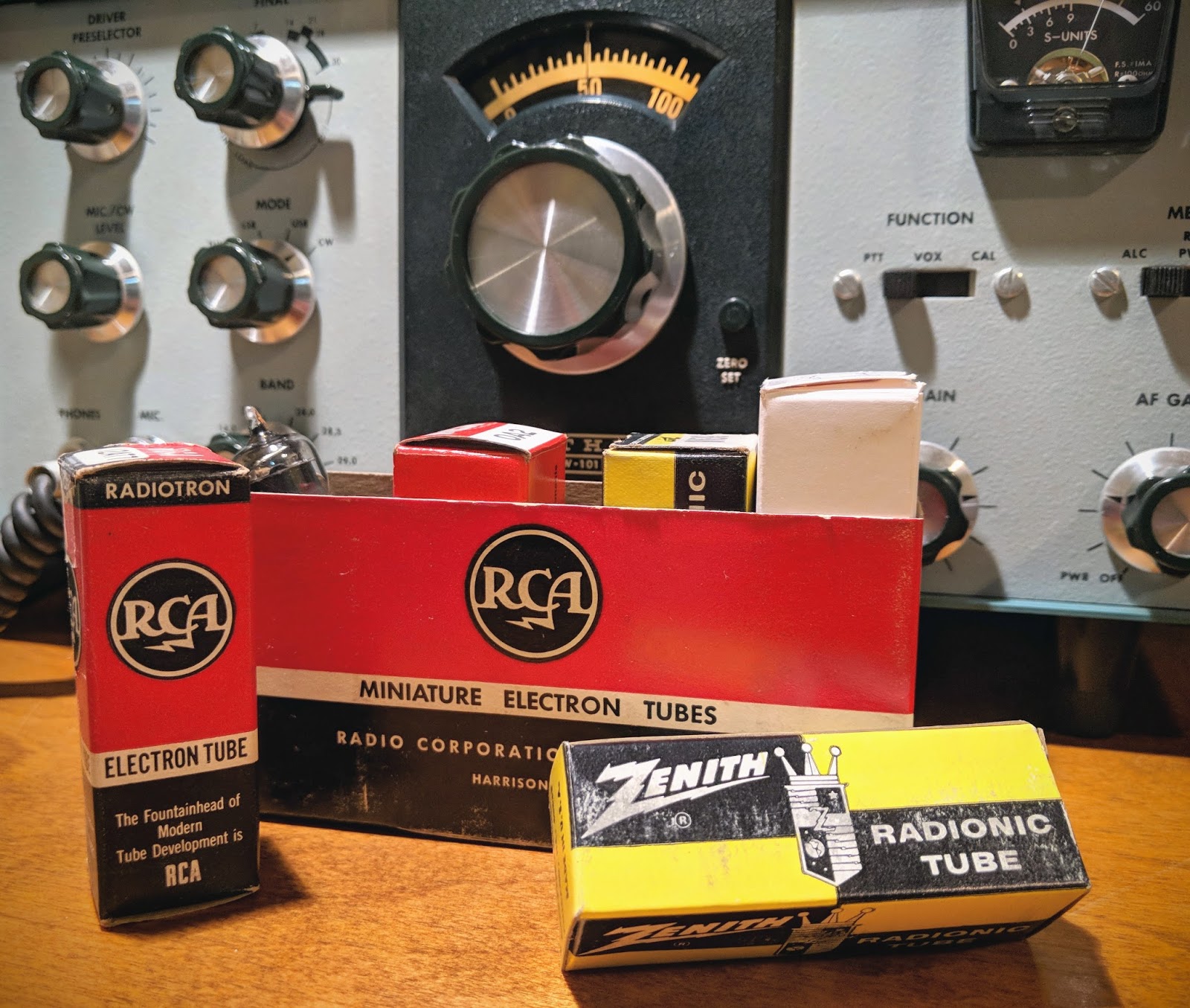
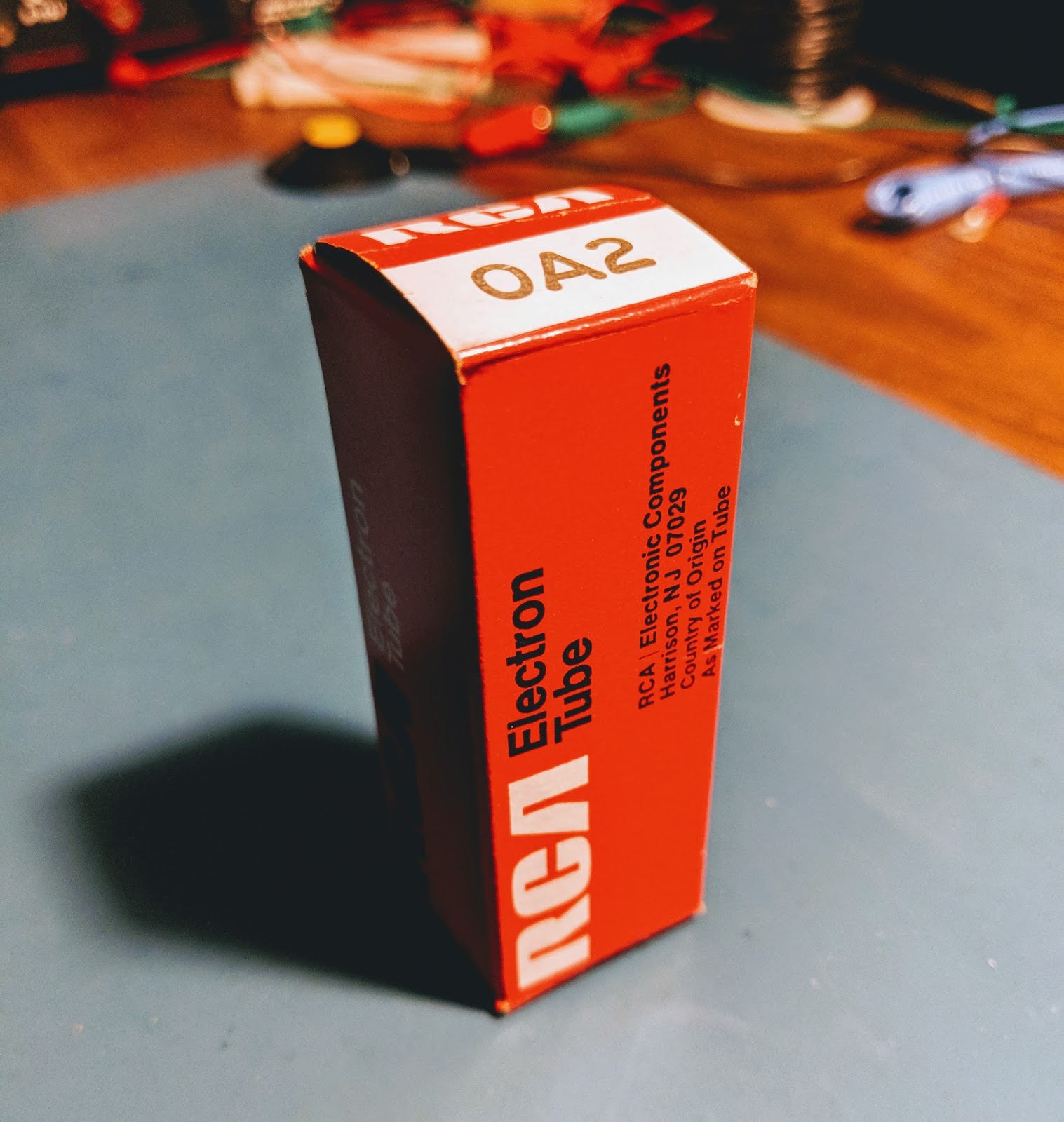
When I started restoring my Heathkit HW-101 I thought it might be difficult to find replacement tubes. I initially only looked on eBay for tubes but then I was directed in a boat anchor forum to the vacuum tube superstore... findatube.com
Bob Dubush offers tubes at prices well below what you'll find on eBay. When you order from findatube you'll receive NOS (new open stock) tubes in their original boxes and may receive them in a nifty original store display box... Ah I can smell the 1950's
He also carries hard to find tubes like the 6GW8 at far better prices than what you'll find on the 'Bay.
So if you've been looking for a good source for all your classic vacuum tube needs visit...
That's all for now...
So fire up that high voltage power supply and warm your shack the old fashioned way
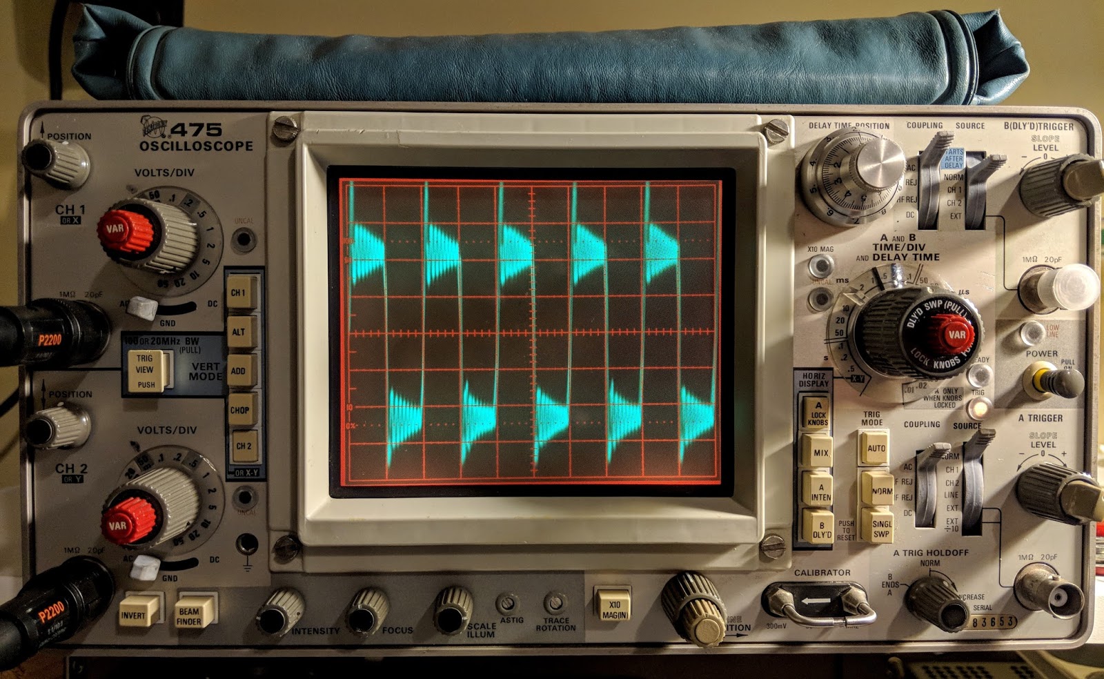
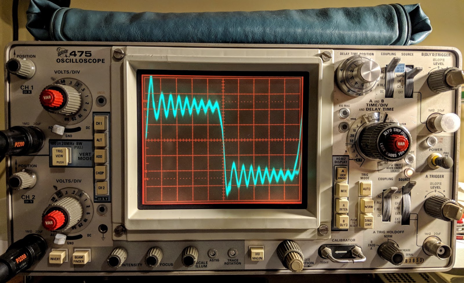
Tektronix 475 Oscilloscope and Android Signal Generator App
When I was debugging problems with my Ten-Tec Century/21, and especially my problematic one-watter kit, I needed to see more than DC voltages. I carried my problem stuff to my friend Paul to see what his scope and signal generator revealed.
Why would a ham need a scope? Audio and RF are both AC (alternating current) and a voltmeter alone doesn't offer much insight into that world of voltage across time and phase.
I almost bought an inexpensive digital scope last year, then thought better of it. Then I almost bought a featured digital scope and checked my wallet and thought better of it. A good digital scope in the 100 Mhz and up range from reliable sources costs upwards of $500. On the other hand, older professional scopes that have been well maintained and kept in calibration are excellent choices and will last a lifetime. You do give up handy on screen cursors for measurements, so you have to count divisions by hand and do the math. You also don't have digital storage in a digital scope, but smart phone cameras and video can make up for that.
When I saw this recently calibrated Tektronix 475 listed in the classifieds on eHam.net for a nice price, I decided it was time to step into the world of visualized AC.
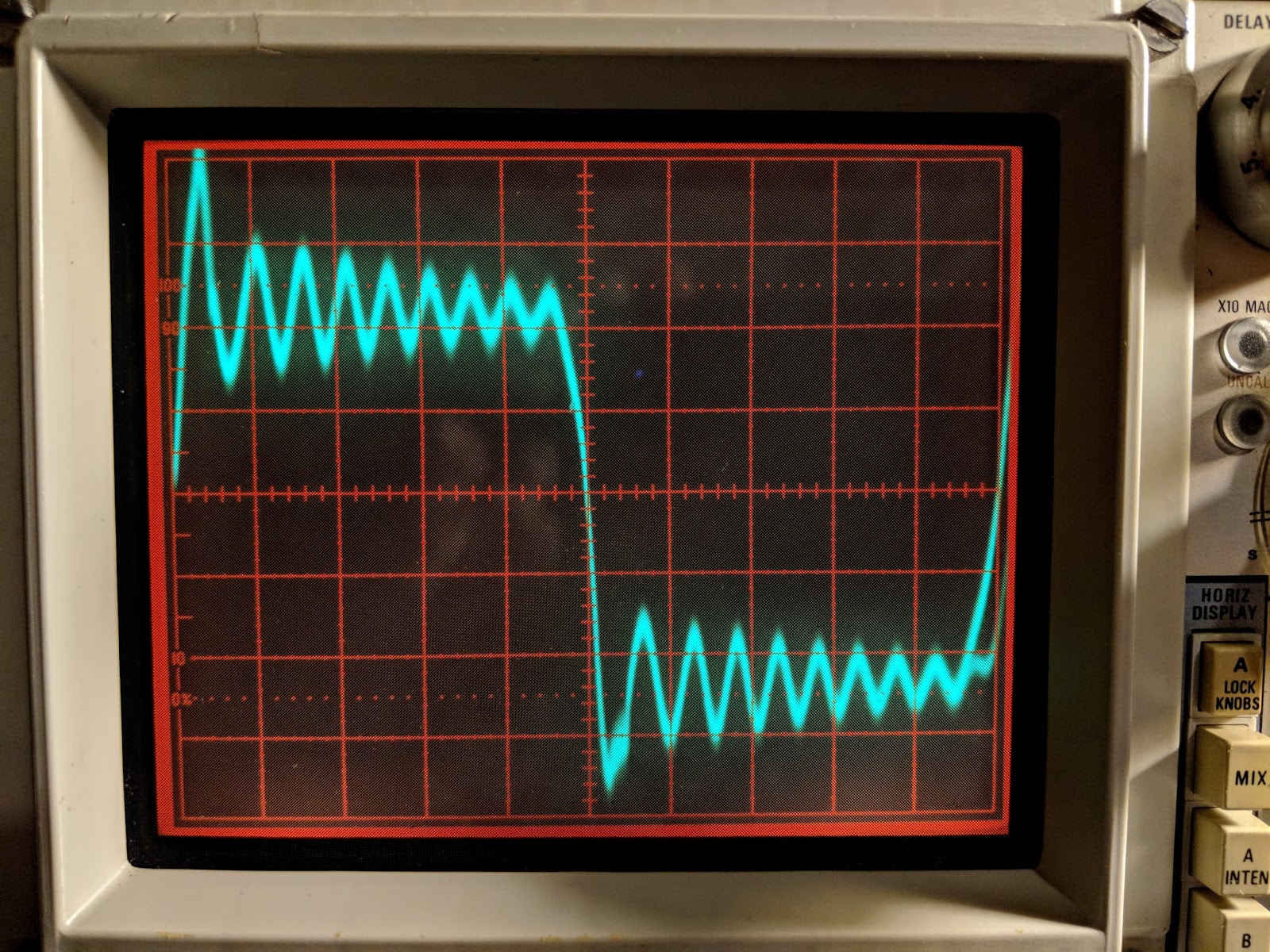
Watching a capacitor charge 250 times a second
The lines are a bit wide because the signal source was noisy
Tek 475 Specs
The Tektronix 475 is a portable (30 lbs), dual-trace oscilloscope with dual time-bases similar to the 465, but with 200 MHz bandwidth and a maximum vertical sensitivity of 2 mV/Div. It is all solid-state except for the CRT. It was introduced in November 1972.
This scope cost $3,000 when it was new. Now you can find them in good condition for less than $200.
Cascaded mode -- 400 μV/Div, 50 MHz with CH1 input connected to CH2 VERT SIG OUT
Time base -- 10 ns/Div to 500 ms/Div, 1-2-5, and ×10 magnifier
Input impedance -- 1 MΩ // 20 pF
Triggering -- 0.3 Div (int) or 50 mV (ext) to 40 MHz, increasing to 1.5 Div/250 mV at 200 MHz; AC coupling >60 Hz; LF REJ >50 kHz, HF REJ <50 khz="" li="">
50>
X bandwidth -- 3 MHz
Z axis input -- 5 Vp-p, 50 MHz
Calibrator -- 1 kHz, 30 mA / 300 mV square wave
Outputs -- CH2 Vert Signal Out, 20 mV/Div into 1 MΩ or 10 mV/Div into 50 Ω; A and B +GATE OUT, +5 V; Probe power jack
CRT -- 8 × 10 cm², P31 phosphor (P11 opt.)
Power -- 110, 115, 120, 220, 230 or 240 VAC ±10%, 48-440 Hz, max. 100 W
Real knobs and switches
One advantage of an analog scope is that there is a labeled switch or knob for every function. No need to dig through menus to figure out how to do something. To me this is the a true advantage to finding a well calibrated, analog scope.
An oscilloscope needs a function generator
An scope let's you visualize AC within a circuit, but when you testing something you often need to inject AC into that circuit. That's the role played by a function generator. Function generators allow you to choose a frequency and a wave type (sine, triangle, square, etc.), or sweep across frequencies.
In general, the higher the frequency they support the more they cost.
If you have a mobile device you can get one that uses your headphone jack as output up to 22 kHz for free...
For a free app it is very nice. It outputs sine waves very well, triangle waves are a bit soft pointed and square waves are for entertainment purposes only. But it is free so I won't complain. In the image below you can see the oscillations as it tries to generate a square wave but the audio amplifier of the mobile device just doesn't have that kind of control.
Frequency Generator App set to 1 kHz
Square Wave?
Square waves are not
Reduce the time base to zoom in
Yea, square wave.... not so much
The square wave is bad but sine and triangle waves look good until the frequency get's near the top of the range or the amplitude is raised too high.
Sine Waves look good
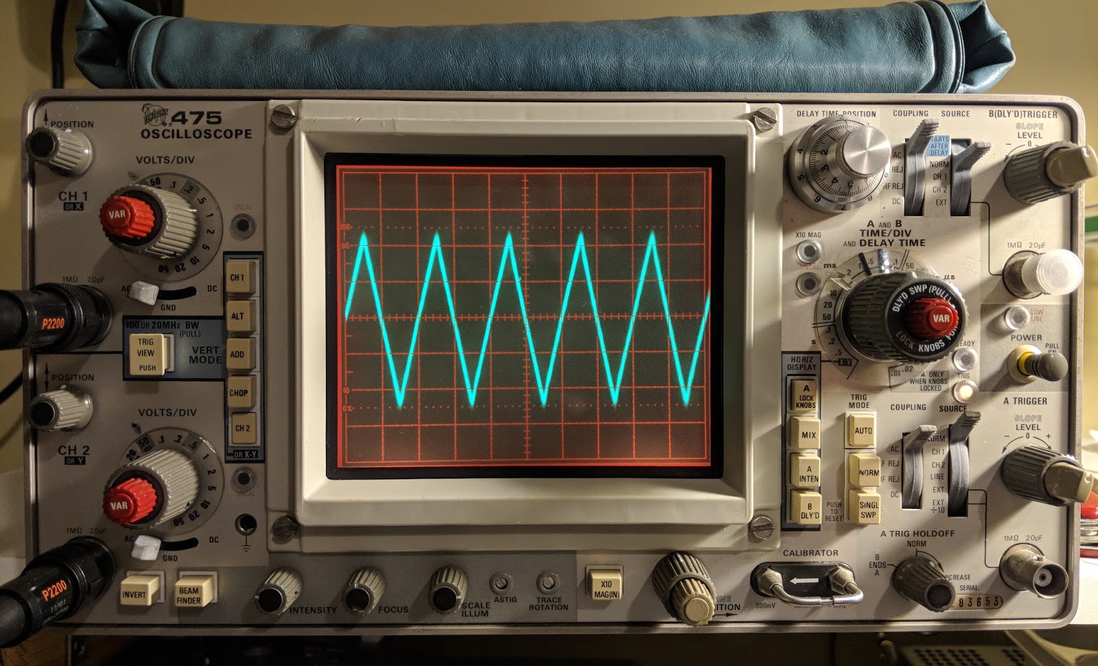
Triangle waves are on as well until you go up in frequency
The free app is inadequate for bench testing
While I appreciate that this would be a useful, portable signal generator for testing audio circuits, I'll be ordering a purpose-built function generator because generating clean square waves is an important test signal to be clean. I also will need a generator that works above audio frequencies, hopefully up the the IF frequencies of the some of the equipment I'm testing.
Only the beginning
Having an oscilloscope is a new adventure for me. I have another 1-watter kit ready to build that I've been holding off on because I wanted a scope for troubleshooting. In the meantime I'm using the scope to watch transistors trigger and measure the timing circuits I'm building and learning how to control the scope. The Tektronix 475 is a feature-rich analog scope. If you plan to fix your own equipment or do some homebrew electronics work a scope can come in handy.
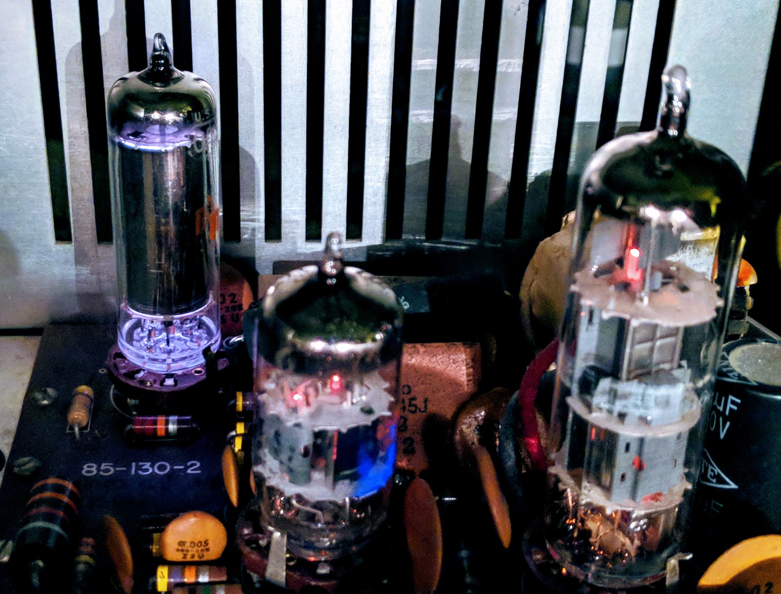
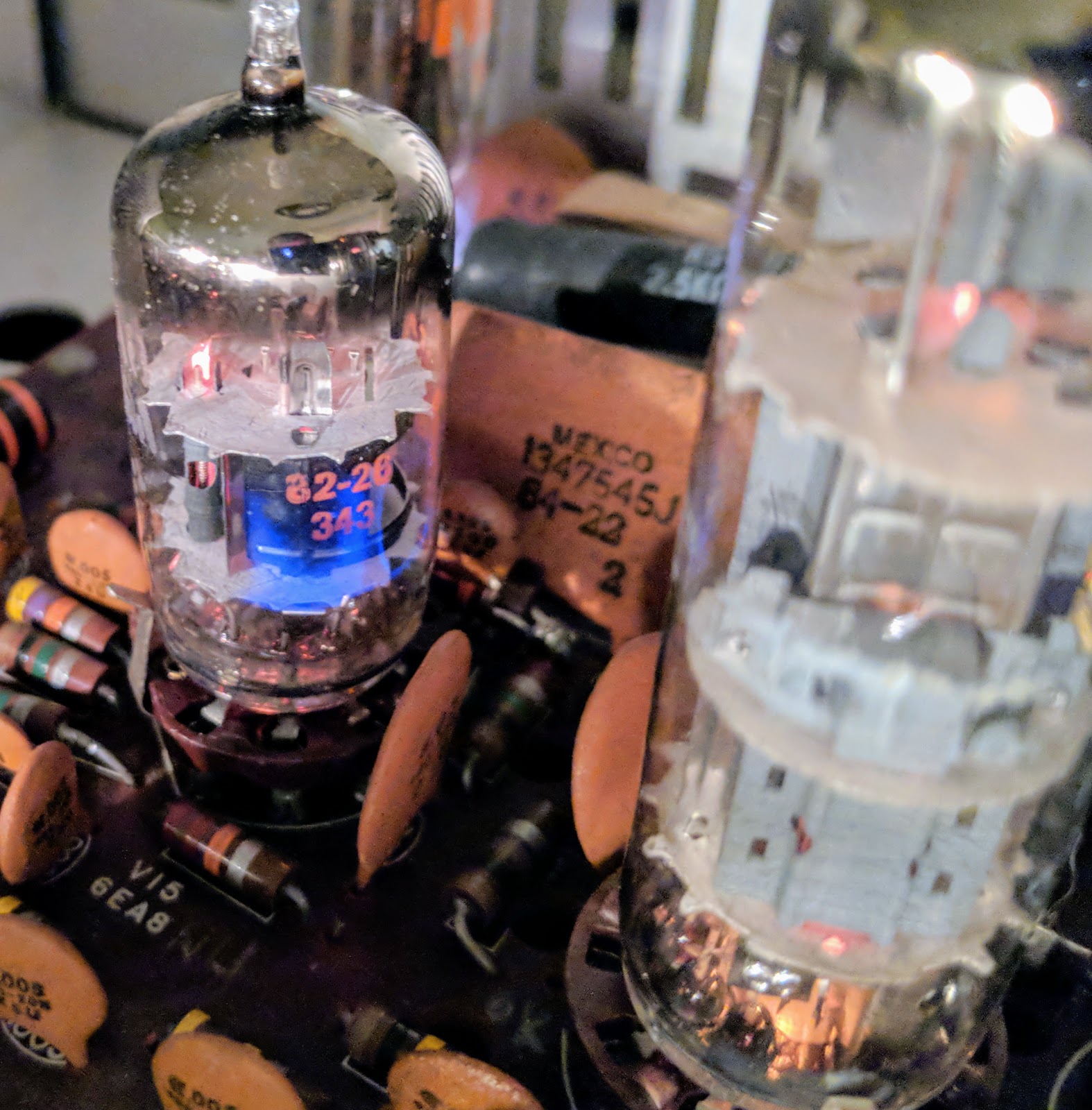
A reader asked me to video the pulsing of the OA2 voltage regulator tube in action.
OA2 VR tube glowing beautifully in back corner
I turned the room lights down to capture the OA2 in its glowing gas glory and noticed a problem with the V15 6EA8 tube that creates the sidetone oscillation and Vox control. A patch inside was glowing a brilliant violet color when the CW switch was engaged. Glowing gas inside a gas filled tube is pretty but glowing gas inside a vacuum tube is a no-no. I've noticed my sidetone volume (which is unadjustable) going a bit soft over the past week and now I understand why. The vacuum tube has developed a leak and has "air" inside. That "air" is mostly nitrogen which ionizes with this brilliant violet color.
Tbis 6EA8 should not be glowing violet
Lots of flatulent tubes
After I saw that I started looking and noticed I also have an 12AX7 beginning to go gassy as well so I ordered some new tubes from www.findatube.com
So let's keep the gases where they belong.
Solved a bit of a mystery tonight
I had a problem that I've just tracked down. Most boat anchor guys would probably already have known how to solve this but it a new discovery for me.
My audio was occasionally scratchy with a bit of popping. Sometimes when working CW the other stations signal would jump around slightly in frequency, like 20Hz - 50Hz.
I'd already re-seated most of the tubes, re-tightened screws, DeOxit'd switches, etc.
Then I noticed that V1's tube shield was not bonded to the tube socket finger thingy (sorry don't know what it's called). The other tube shields were soldered and I hadn't noticed that this tube shield was new and looking at the socket spring thing appears it had never been soldered. After pulling that tube and its shield I scraped the paint from the shield where the socket spring presses onto it and cleaned the socket spring as well. Apparently those tubes leak RF and the tube shields catch the stray signals and send them to ground. Without proper bonding the tube is spraying RF around.
That turned out the be the problem, now all is good. Received signals are rock steady and the audio is very clean.
Tube shield needed to be grounded to the socket spring
This problem had been periodic and was driving me a little nuts. I'd read that grounding the tube shields was important but somehow I'd missed that this shield was not properly bonded to the finger thingy.
On the positive side, I am growing a tube collection by purchasing replacements that are not needed :)
That's all for now
So lower your atmospheric pressure and raise your B+ voltage
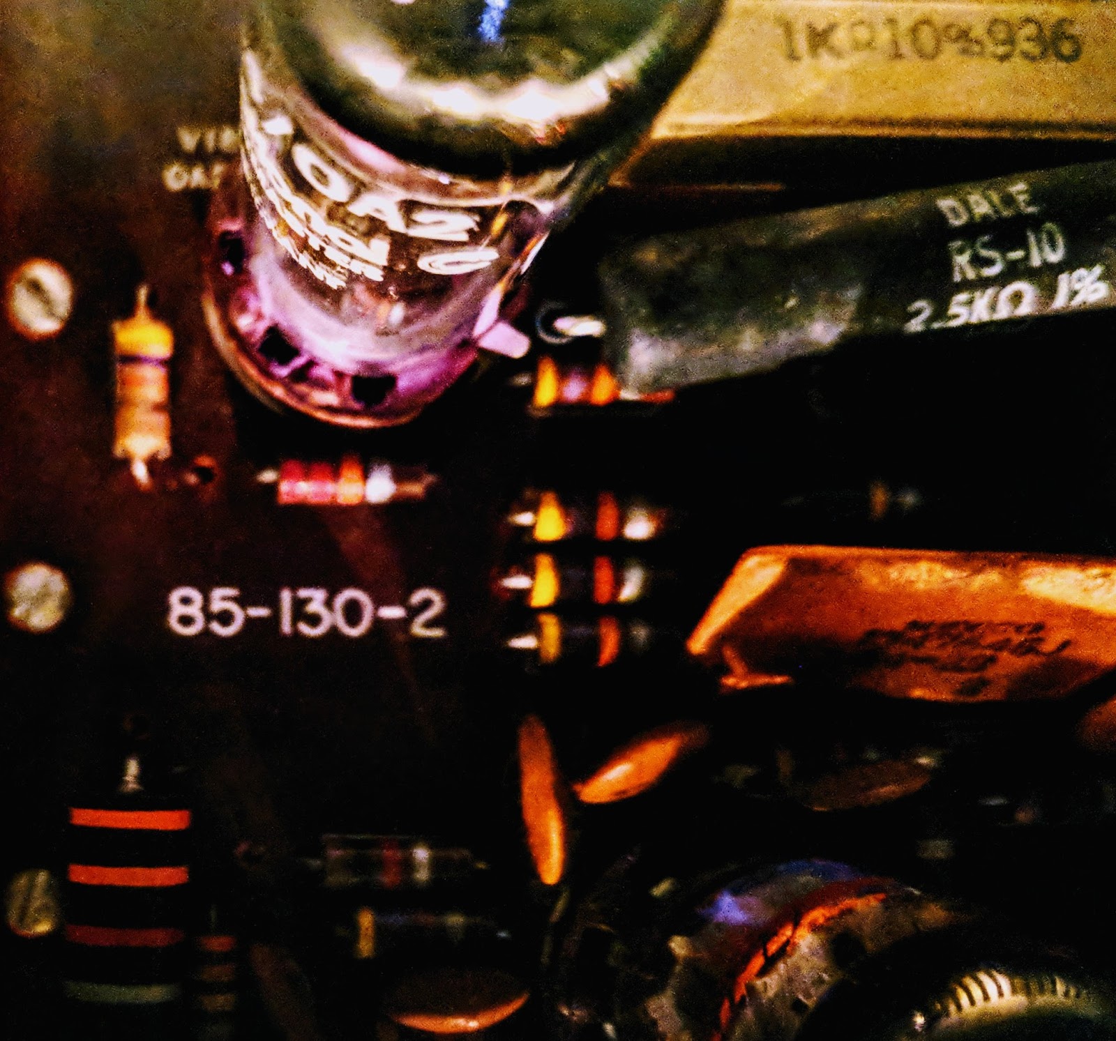
The Meter on my Heathkit HW 101 stopped displaying ALC (dropped down to the negative stop). So, I opened up the old rig to have a look. I found that the B+ voltage was reading 33 volts higher at one of the test points than it should. Ultimately that voltage didn't turn out to be the problem with the alc meter instead the meter switch had become dirty and needed to be cleaned. But in the process it got me to studying the way voltage is regulated in the Heathkit and I learned a bit about voltage regulation tubes like the OA2 used by Heathkit.
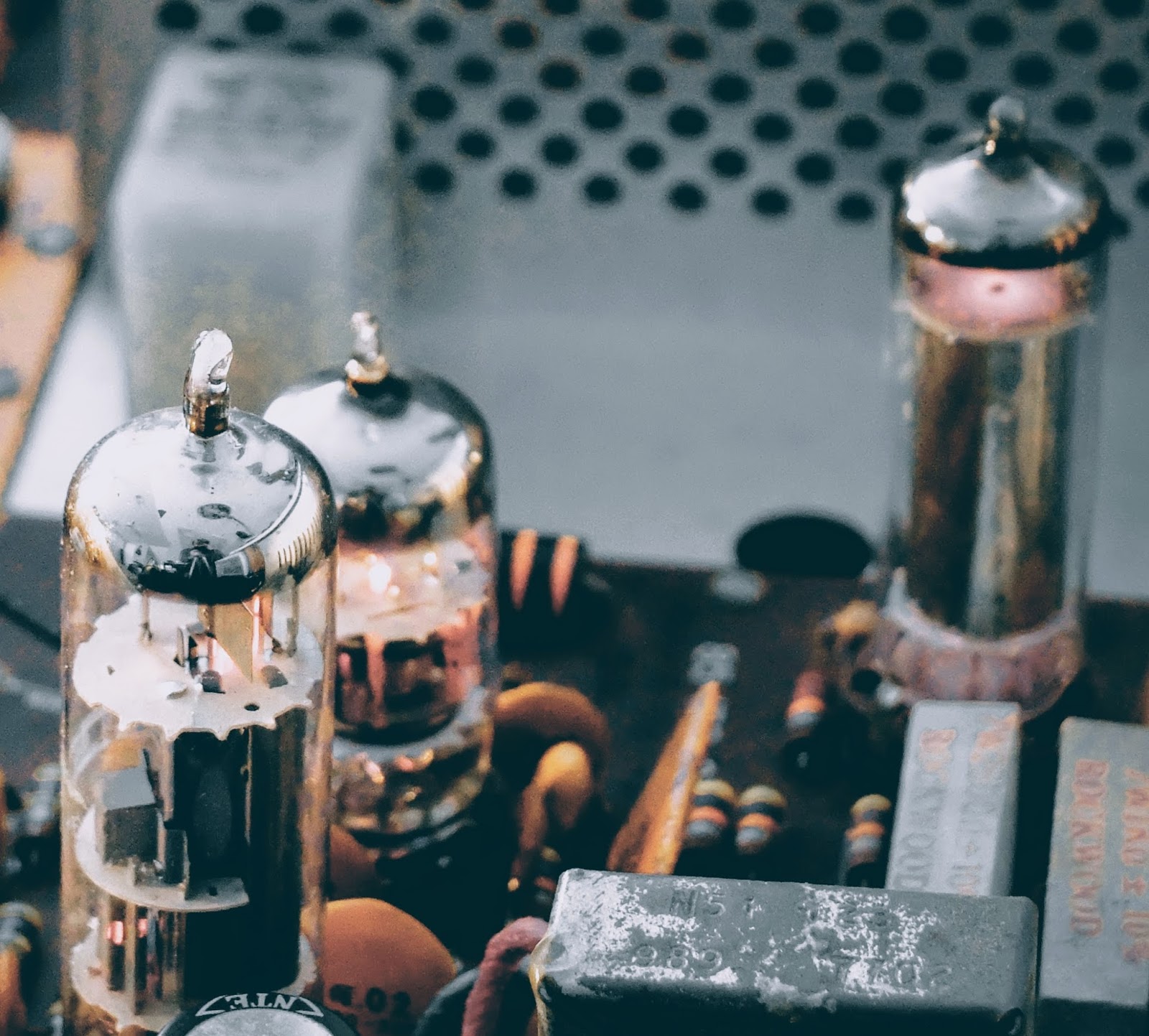
OA2 tube
OA2 in action at the right rear of the Audio board, notice the glowing gas inside
More Glow...
Look at the pretty violet glowing gas in the OA2
The OA 2 is actually not a vacuum tube it contains a gas that ionizes and in the process of ionization acts as a voltage regulator. In a vacuum tube, if you see glowing gas inside the tube that means it's leaking and has become "gassy", that's a bad thing. In the case of a gas filled tube like an OA2 you expect to see glowing gas and if you do not, then there's a problem.
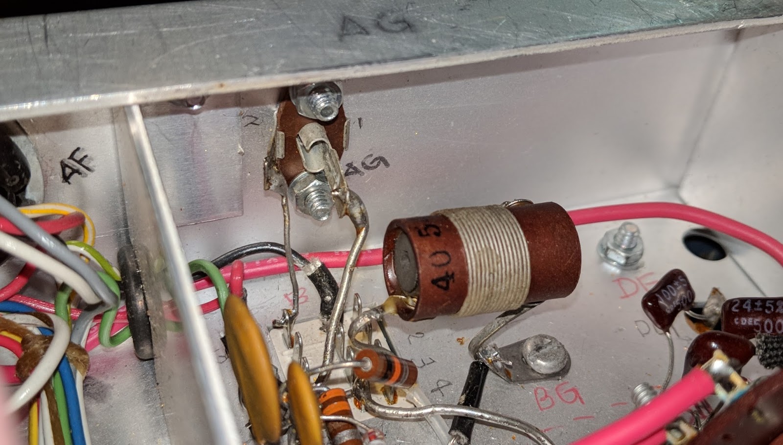
In this case The OA2 regulates voltage to 150 volts and current is limited by the two high-wattage resistors connected in circuit to that tube (seen beside the OA2 in the photo above). Those resistors are dissipating a lot of heat. I measured over 300F degrees with my IR temperature gauge (ouch).
Tube Testing without a tube tester?
I emailed one of the members of my local club, Joe WA4GIR to ask about tube testing and he sent me the following, which he gave me permission to post:
The lack of a tube tester is not a limitation. You can tell a lot about a tube test by looking at the voltages in the circuit. If the filament goes out, the tube is dark and does not conduct. That one is pretty obvious. If the tube cathode loses it's ability to emit electrons, the voltages dropped across the cathode resistor and any resistors in the plate or screen grid circuits will change (the voltage drops across those resistances will drop). A good tube tester will measure the ability of the tube to vary the plate current for changes in grid voltage, and you can see this with a scope by looking at the AC voltages on those elements, at least for the audio circuitry. Probably not so much for the RF circuits as you are affecting the circuit when you probe it. The best way to check for a suspect tube is to replace it with another. I have 0A2's new in the box. I may have the other tubes pulled from radios but it takes longer to look through those as sometimes the numbers are hard to read. Hint. to bring out a faded number, rub it on the hair on the back of your neck-- better if it's oily.
A lot of resistors in old tube-type radios were 20% tolerance so don't expect the voltages to be that precise. Tube rigs had much more variability than modern solid state circuits. For the unregulated voltages, the precise voltage will depend component tolerances, tube health, and line voltage. The line voltage here is about 125 when where I lived in Raleigh it was around 110. You can do the percentages but that alone will account for some of the variation you might see. I don't think that any of your tubes were damaged by overvoltage. If they are drawing too much current, they will get hot, and in severe cases, the plates will glow red. That's a concern. Much less than that, the life might be reduced but I don't think you will see any short term effect. When I've run tubes too hot, you might see signs of the tube going gassy, which is indicated by a blue low in the space inside the tube that is supposed to be a vacuum.
If you want to see the plates of a tube glow red, operate the final mistuned so it is drawing too much current. They will glow red, haha.
The voltages out of the 0A2 are different -- they should be held pretty closely to 150V. I don't know the exact tolerance. It might be a few percent. So in your radio, 150V supply and any that are derived from it are the only ones that would have a tighter tolerance. The 0A2 has an operating current range of 5 to 30ma, and an operating voltage of 150V. The supply voltage should be at least 185V to get the tube to "fire" but once "on", the voltage feeding will drop to the 150V level and be regulated there by the action of the tube which causes the voltage drop across to change (like zener diode regulators). The regulation comes from the fact that a very small increase in the voltage across the tube results in a significant increase in the current so the resistor values are chosen so that the current through the tube remain in the 5 to 30ma range as the input voltage and the current draw of the regulated circuits varies for whatever reason. Remember the current draw when you first turn on the rig will be low because the tubes don't conduct until the cathode gets heated so the designer must account for that in the selection of the input resistors to that circuit.
More to learn about hollow state
As a young-ish ham I certainly have a lot to learn about old tube radios but I'm enjoying the journey. Just the thought of transistors operating by thermionic emission, tossing their electrons across empty space, being attracted to a plate with more positive voltage is fascinating to contemplate.
That's all for now
So lower your power... or at least regulate it with a OA2... and raise your expectations
I've been making modifications / upgrades to my old Heathkit HW-101.
I've had a good number of CW QSOs and a couple of phone contacts with it so far and received good reports. One concern I had, regarded losing the first DIT of a letter on initial relay closure. There is an upgrade article for the HW-101 with a section describing a fix for losing the first DIT of a letter on the initial close of the relay. The modification involve replacing a resistor with a lower value that triggers the VOX. It's a resistor change from 470k to 1k which seems kind of extreme to me.
According to the article you will hear the initial DIT in the sidetone but above 20wpm that DIT is not transmitted due to a delay of the relay closure because it's driven by a VOX circuit.
This test is difficult to describe to a remote CW operator.
I recalled that webSDR stations usually offer a remote recording facility. I found a webSDR station that was within propagation on 40m today and sent my CQ with my call while recording from that remote station. My call, of course, begins with the letter A, which begins with a DIT. I paused for the VOX delay to timeout between sending my call-sign, thus causing AA4OO to be sent with the relay closing at the beginning each time. I started the recording before my call and stopped when I was finished and downloaded it.
remote webSDR station recorder
I confirmed, that although the initial DIT was shortened a bit above 20wpm, it was still being heard and didn't affect copy of words that began with a DIT on relay closure. So I've decided to not do that modification at this time. I previously used DEOXIT on the both sets of relay contacts in the HW-101, because there seemed to be some corrosion present that was affecting receive at times, and that has cleaned up the performance of the relay considerably.
So if you're wondering how to get a remote signal report when no one is answering your call the facilities of a remote webSDR station may help.
NOTE: The HW-101 doesn't have a precise VFO readout, even after calibrating it with the built-in crystal calibrator. I use the reverse beacon network to spot me and take the frequency reported by remote beacon to enter into the frequency of the webSDR station to find my signal.
This works for getting a SSB report as well
This is also useful for determining how your SSB signal sounds. So if you verify your audio from a remote station, try using a remote webSDR station recording capability for checking your rig.
One way transmissions are prohibited aren't they?
You may be thinking that using webSDR to check your station might be considered a one-way transmission or fall under the prohibition to broadcast by amateur stations. But Section 97.111(b) provides for one-way communications. In summary, auxiliary, beacon, space and stations in distress are specifically authorized to make certain one-way transmissions. Additionally, an amateur station may transmit the following types of one-way communications: Brief transmissions necessary to make adjustments to the station; ...
So just keep your transmissions brief and only use them to make adjustments. I send them as a CQ and follow-up if I receive an answer to my call.
I picked up an old, high impedance Heathkit microphone having the appropriate 2-pin connector. One pin is the mic line and the other is for the PTT switch. The shield is common.
I set the mic level to indicate some movement on the ALC and peaks were occurring around 100w. QRP SSB will be tough to achieve.
I worked a few stations on 80m and they delivered great reports and offered their own stories of Heathkit radios.
The old rig is certainly a conversation starter.
That's all for now
So... well, my QRP saying doesn't go with this post, so... warm your tubes and smell the cooking resistors
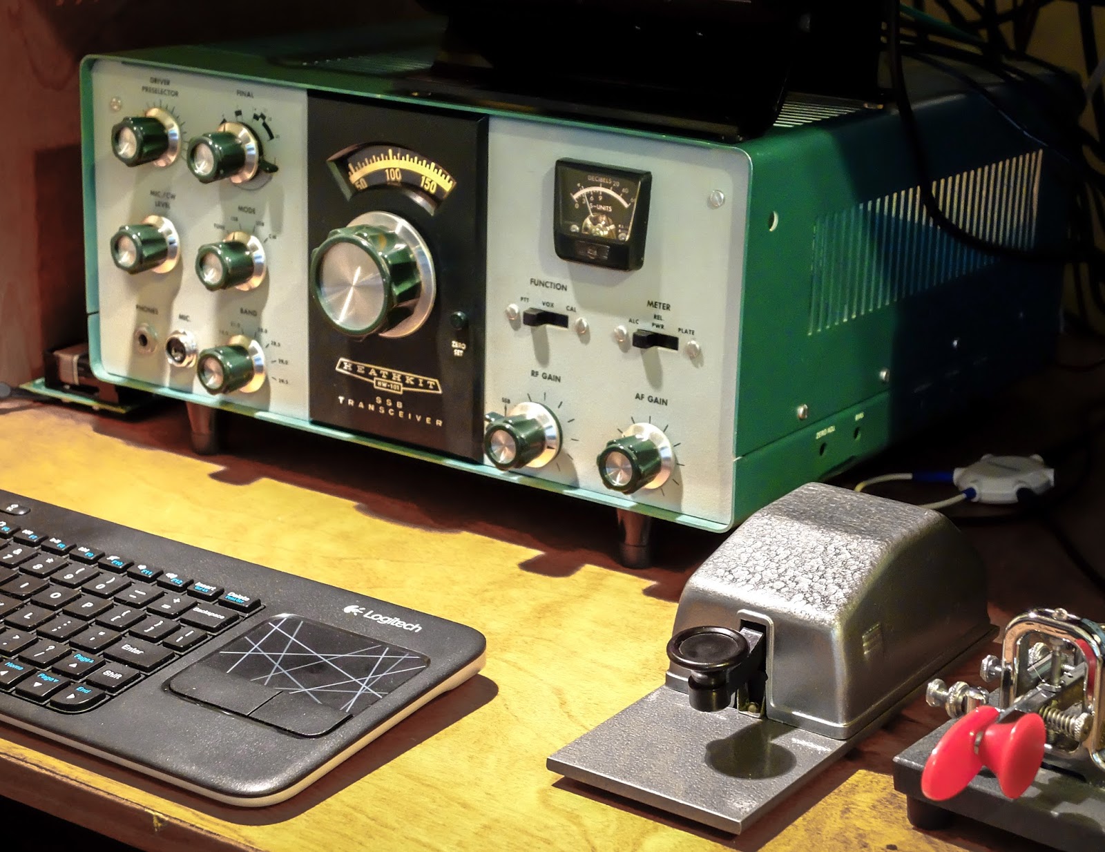
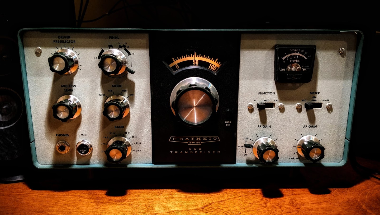
Heathkit HW-101 after it's first QSO under new ownership
I completed my rebuild of my Heathkit HP-23B power supply this morning. There was a bit of frustration on my part as I followed the instructions because they only have photos of a HP-23 which has adjustable bias and no LV switch.
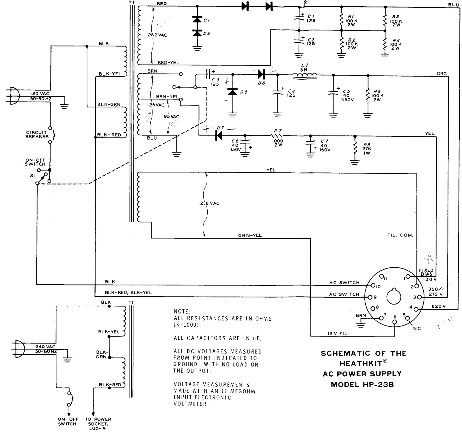
It left me scratching my head a couple times, and I had to locate a schematic of a HP-23B to complete the work.
Heathkit HP-23B Schematic
I really need to learn more about electronics
In the midst of the rebuild I thought I had a problem with the transformer. Both low voltage winding taps (275v and 350v) showed very low resistance (about 5 Ohms) to chassis ground, which led me to believe there was a short in the transformer.
I called my mentor in all things Ham radio, Paul AA4XX, and described the issue. He walked me through the schematic and had me unsolder a couple points to confirm his guess that all was well. That double tap, low voltage winding presents very low resistance to ground but it is not a short in the world of AC. I continue struggling to wrap my head around the differences in AC and DC, but I'm slowly learning and fortunately haven't caught anything on fire yet.
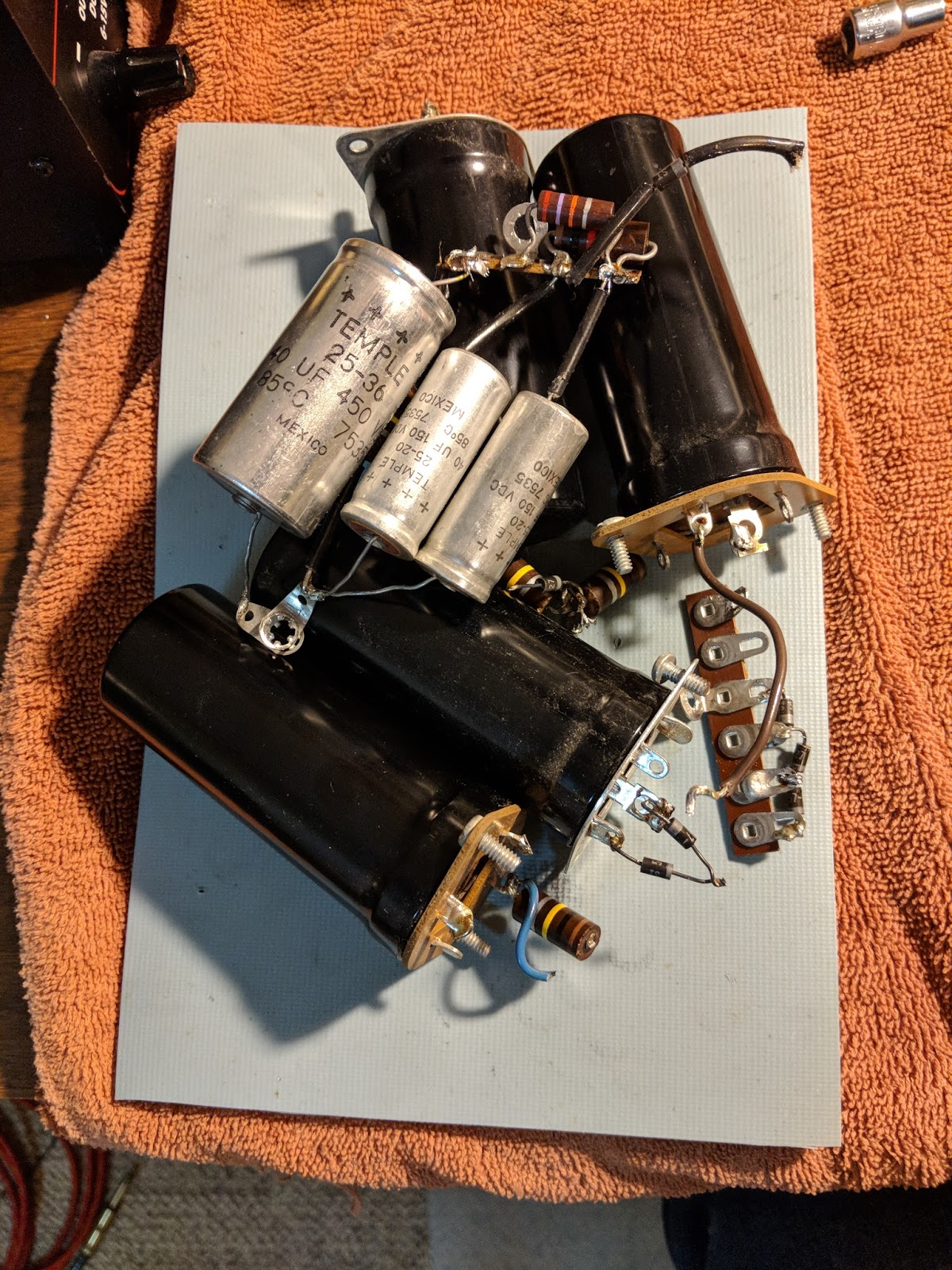
Out with the old, in with the new
Old components
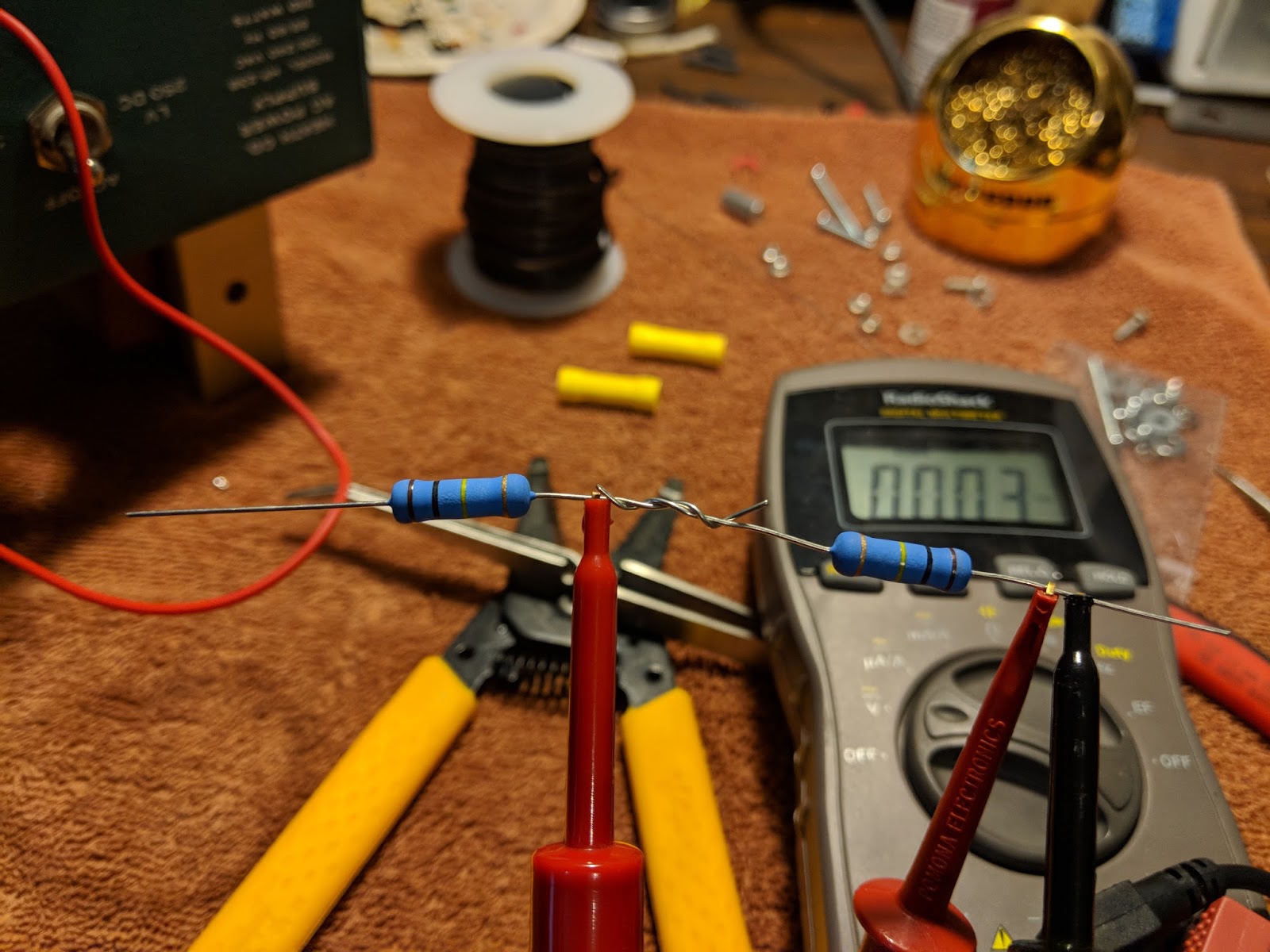
Testing High Voltage
My Multi-meter can only measure up to 600v, so in order to measure the 800v output I used two 3 watt 100 kOhm resistors in series as a voltage divider. When in use, the MM will read half the voltage.
Voltage divider for measuring the high-voltage output
With the voltage divider the HV power measured 401v which works out to 802v undivided
Completed upgrade
The kit places all the components in the base and the holes that the old big filter capacitors used to be in are now just ventilation. I need to put a wire shield over those holes because high voltages are present just below, as well as some really hot resistors. With the top cover back on it, there shouldn't be a problem but the wire mesh shield is still recommended, especially if it's to be used inside a Heathkit speaker, where the top cover is not used.
With the PCB board, all the components are out of sight in the base except the big resistors
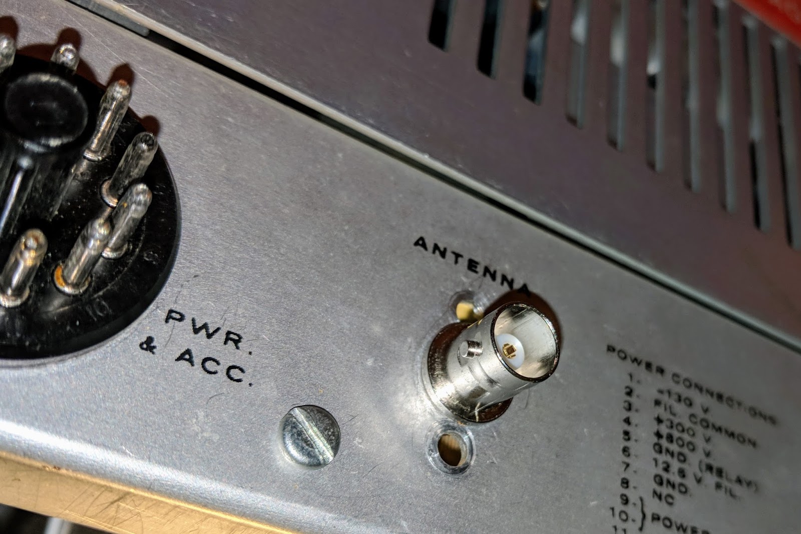
Replaced the HW-101 antenna connector with a BNC
Original antenna connector was a RCA with questionable integrity.
Original RCA antenna jack (viewed from inside chassis)
Replaced with BNC jack which fits without enlarging the original hole.
New antenna jack
The old radio now has power
I replaced the old paper 350v 20uF electrolytic capacitors in the HW-101 and then connected the power cable and switched it on via the switch in the HW-101. I didn't hear any audio at first and thought something was wrong. Silly me, those tubes need a bit to warm up. After a minute I was hearing audio and used the built-in crystal calibrator to check the VFO dial. It was pretty close to spot on.
I ran through some initial checks according to the Heathkit manual. Receive worked well. I listened to some SSB and then dropped down to the 40m CW portion of the band and listened to CW. I waited about 30 minutes for the tubes to warm up. I didn't hear any drift on CW stations I was monitoring.
I found an open frequency, checked the plate current and then tuned up, outputting only about 10 watts because I don't know what state of alignment the finals are in yet. This is the first time I've tuned a tube rig and that was interesting. You have to peak the preselector in receive mode first, then when in tune mode, quickly work back through the preselector, final tune and load levers to peak the RF output. It reads more complicated than it actually is. My OCFD antenna has about a 1.7:1 SWR on 40m so it didn't need much tweaking from the initial settings.
I tuned around and answered N4PGJ, Ron in NY, and had a brief WES exchange. The relay control time set by VOX delay needs to be bumped up a bit as it was dropping between every word break, but other than that it worked like a charm.
I'll make a video soon, but initial impressions are positive. The audio quality was astoundingly good, and the CW filter really did a much better job than I expected. It has a very pleasant sine-wave sidetone rather than the raspy square wave sidetone of my Ten-Tec Century/21. I really think I'm going to enjoy using this old rig.
UPDATE
I got the rig buttoned up and on the desk. Here's a video...
Breath new life into a Heathkit HP-23 power supply
My recent interest in restoring a 1970s Heathkit HW-101 tube radio, is leading me down quite a winding path.
Before I can even test the HW-101 I must be able to supply it with power. Vacuum tube radios need multiple voltages for the different tubes in use. In the case of the 20 vacuum tubes used in the HW-101, it needs the following voltages to operate, 800v, 350v, -130v and 12.6v.
If you've followed previous posts you'd read that I thought I'd be clever (as if), and restore a Heathkit power supply that runs off of 12v so that I could use it mobile or from my 12v linear supply in the shack. Well, I restored a HP-13 and if you read that post and watched/listened to the video you and I now both understand why operators only used those power supplies out of earshot, like in the trunk of their automobile, or in the next county. It makes way too much audio racket to be at my operating position.
So, pouring a bit more money into this effort, I bought a AC/mains powered supply; the Heathkit HP-23B... but alas it has old components and also needs to be restored.
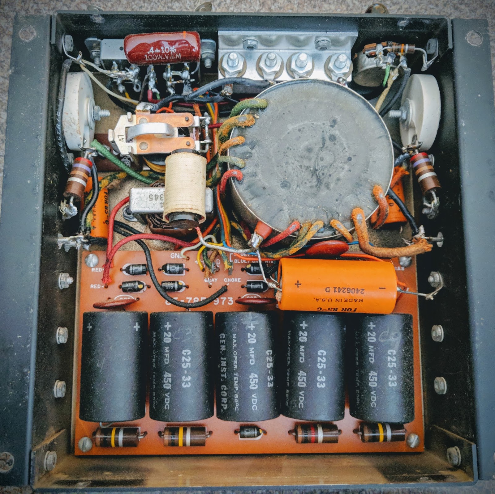
Heathkit HP-23B
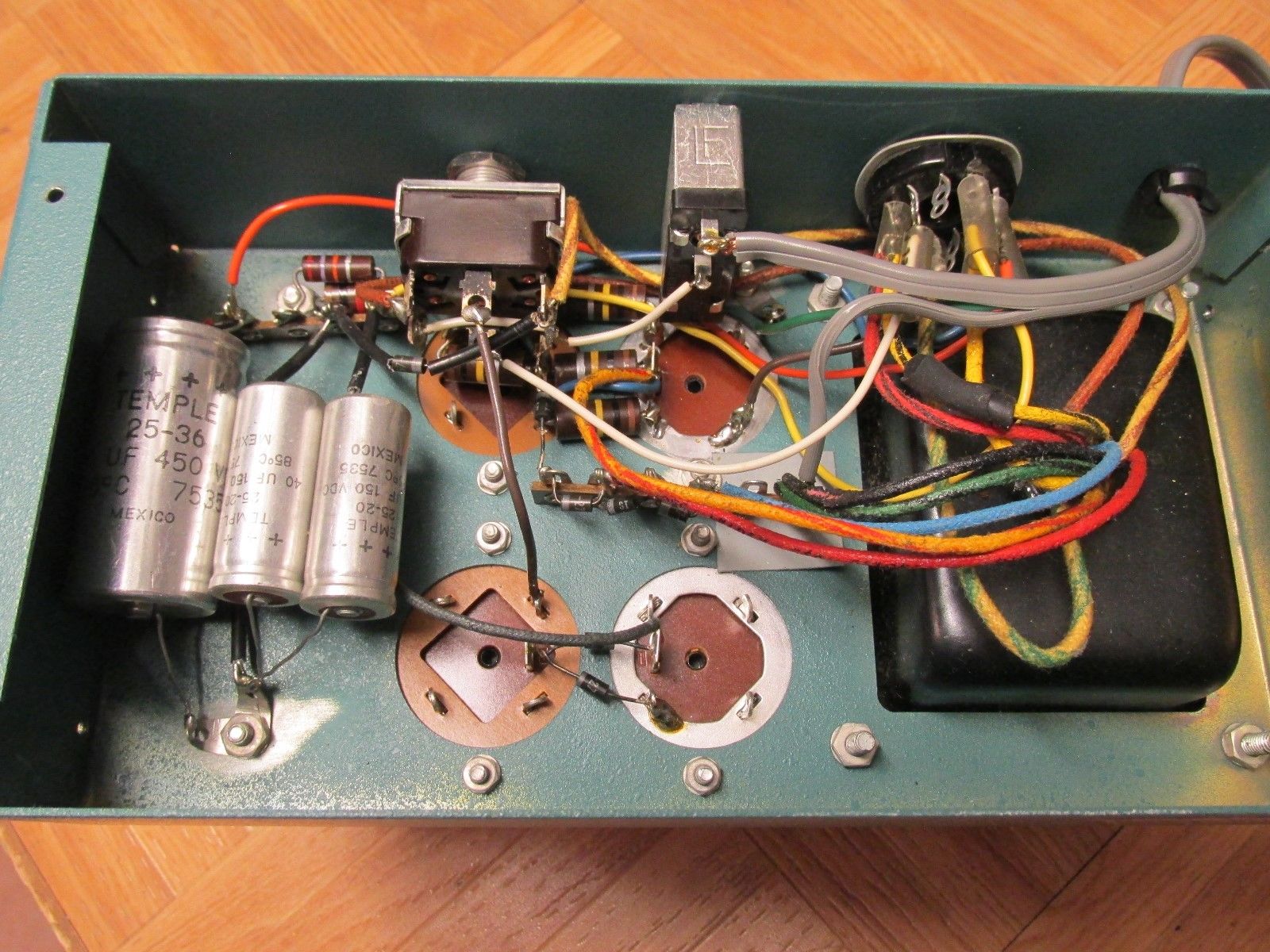
No direct replacement capacitors
Those large capacitors in the first photo have no modern equivalent in terms of the pin-outs and the HP-23B chassis used some phenolic wafers that are rather fragile after this many years, to hold those capacitors. There are some videos showing how to adapt modern capacitors to fit and that would help maintain it's classic look, but it seemed a bit fiddly to do. Also, you can see that in the base of the power supply there are numerous other axial caps and resistors that need replacing and it's a frightening mess of wiring in there given the voltages present.
Old Heathkit Parts to the rescue
This is such a common issue with these power supplies, that K8GNZ designed a PCB compatible with modern electronic components that would replace that tangle of wiring. It can be ordered from Old Heathkit Parts for a reasonable sum and comes with a CD listing the components that need to be ordered as well as instructions for building the PCB and wiring it up with the HP-23B.
This board gives you one convenient place to populate all the components and hookup the wiring in the HP-23 chassis.
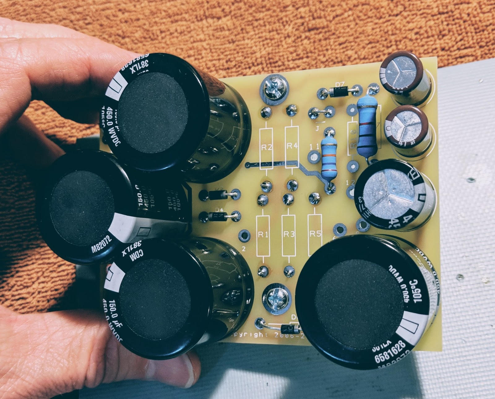
HP-23D PCB
The 3w 100k resistors go on the bottom mounted 1/4" off the board so they don't burn the board (they get hot)
Partially populated board
All done, ready to wire up to the HP-23 transformer and choke
Note how much smaller the 4 new 450v caps are than the ones they replaced in the photo at the top of the post.
The next step is to tear down the old HP-23B and prepare for this board to replace its innards. Maybe this weekend.
Gotta get the power from the supply to the radio
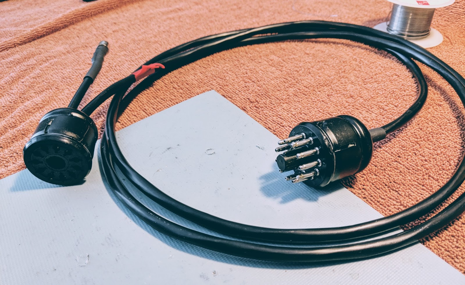
The power supply has 8 connections to the radio and Amphenol 11-pin plugs are used for the connections. I purchased a wiring kit on eBay that I'm not really pleased with so I won't provide a link to the seller. It works but there were some compromises. If I need another cable I think I'll just find a used one.
Power cable
I also added an amp-key line out from pins 5 (ground) and 11 (relay) for future projects. I terminated it into a female RCA plug. I have previously used the amp-key line from my Ten-Tec Eagle to trigger the protective relay on my SDR, so I may use it for that, or something else. I figured as long as I was soldering 16 connections in those plugs I could solder a couple more.
Amp-key line out
I've also purchased an additional NOS female Amphenol 11-pin chassis plug that I plan to wire up from the Grove connector on the HP-13 so that I can just use the HP-23 cable with the HP-13 if I wish to in the future.
So just a few more hours of work and I should be able to light up the old HW-101 for the first time in decades.
The smell of hot tubes awaits... or magic smoke... I hope it's the former
As seen in my previous post I've taken the dark plunge into the world of tube radios. I want to start restoring my Heathkit HW-101, but before I can do that I must be able to power it. As I previously wrote, I taken the road less travelled and got an old (circa 1965) HP-13 mobile power supply because I thought it would be nice to power the radio from a 12v source rather than mains.
Unrestored HP-13 with broken solder joints and trashed capacitors
Well there seems to be a reason these don't seem very popular... I'll get to that.
I found a very nice article from RDF-Electronics regarding modernizing the HP-13 power supply. That document includes the components and part numbers for everything you will need to restore your HP-13. My parts arrived from Digi-key and I began snipping and desoldering the old component off the PC board. The replacement electrolytic capacitors are all much smaller and have radial rather than axial leads. That makes placing things on the board require a bit more creativity.
HP-13 Schematic
The only truly problematic components to replace was replacing the twin positive axial lead electrolytic (C11) with two electrolytic capacitors (space issue) and replacing the C1 and C12 due to the tricky wiring around the transistors.
The orange cap on the left under the Q1 (C1) was tough to replace with a much smaller radial lead capacitor
The article suggested replacing the original 100 uF/50 V capacitor with a 4,700 uF/35V to better control ripple. The article goes into quite a bit of detail concerning his testing of ripple using an oscilloscope. Finding room for that big cap and it's accompanying filter disc required a bit of creativity as seen below, where it's laying on its side between two of the rectifier caps.
I will glue all the caps to the board before I put the power supply into service.
New capacitors and diodes
I replaced all the electrolytic caps and diodes. The diodes might have been ok but they are blocking over 300 volts each and a single failure would let the smoke out for sure.
Out with the old
In with the new
All the resistors except one 100k 2 watt were ok. So I only replaced that resistor. The 1.6kv disc caps even measured ok.
The internals look a bit different now with the new caps standing up where the old, larger axial lead components laid flat.
Ready for testing
Testing
After performing resistance and continuity checks I buttoned it up for the test.
The Noise
I had no idea how audibly noisy this power supply would be. The switching that occurs in the transformer creates a very loud whine. I understand why hams would install these in the trunk. There's no way you'd be able to stand this for long if it was sitting next to your station.
I have a longish intro in the video. Skip towards the end to hear it powered up... turn your volume down when you see the "hearing protection" sign come up in the video.
Conclusions
This was a good learning experience. I learned about high voltage transformers and got some practice restoring older equipment. I practiced electrical safety and didn't kill myself, so I'm pleased about that.
I now have a power supply I could use from a sturdy 12v source if I needed it, BUT due to the noise in operation I'm going to look into restoring a HP-23 which runs off house mains (AC) and is mostly silent.
I'll keep this on the shelf waiting for a day that I need to run the HW-101 mobile.


