❌

Normal view

There are new articles available, click to refresh the page.
Before yesterdayMain stream

Fox flasher MkII update 9/2024

By: Owen
5 September 2024 at 22:21

Fox Flasher MkII and several follow on articles described an animal deterrent based on a Chinese 8051 architecture microcontroller, the STC15F104E.

Fox flasher MkII update 7/2019 documented a rebuild of the enclosure etc.

This is an update after five more years operation outside.

Above is a pic of the device. The polycarbonate case has yellowed a little. Importantly the cheap PVA has not crazed, it is kept dry by the outer enclosure, and a hydrophobic vent helps keeps the interior dry.

The battery is a pouch LiPo single cell, it is in good condition. A previous trial with 18650 LiIon cells showed they were unsuitable for the environmentals.

Last update: 6th September, 2024, 8:21 AM

Boxing an Arduino ADF4351 Signal Generator

By: GI7UGV
22 October 2017 at 00:34

After reading a Radcom article about a 10MHz locked ADF4351 Arduino controlled Β signal generator thanks toΒ Alain Fort F1CJNΒ described here, Β it seemed the perfect module for testing equipment locally as I didn’t have anything like this.

Once the pieces arrived from China it worked perfectly with a 10MHz GPSDO input using the instructions from Alain’s page above and the black ADF4351 board after disconnecting the on-board 25MHz clock.

MTuMxBx

When connected, the above worked fine and did okay on the desktop it wasn’t suitable for moving about or with the jumper cables for long term storage/use. A box was ordered large enough to place all of the bits in and to allow SMA & DC inputs as well as another shield that didn’t have the headers I’d put on the above one.

The Arduino LCD/Button shield works well but doesn’t lend itself at all well to being installed in a box. The LCD brightness adjustment trimmer is too big, there are some header pins sticking up to the LCD level and the buttons are too far recessed for access through a box. Some discussion on the ukmicrowaves mailing list gave pointers for getting around these problems.

Firstly the buttons were all removed and the trimmer was moved to the other side of the PCB.

JtlFAbyΒ I wasn’t sure of the size of buttons to replace the originals with to allow them to be pressed when mounted in the case so I had also ordered a mixed pack on eBay to allow picking the appropriate size. I also ordered some white caps for the tops which would eventually be glued on. I eventually settled on the combination lush with the LCD.

fd7Liskg

Now came the part I wasn’t looking forward to, drilling and cutting the case. The LCD shape along with the four mounting holes was drawn out based on measurements from the board and cut. I don’t have any nice tools for the LCD rectangle cut so cut two sides with with a hand hobby saw and others with a rotary tool to compare the finish as wasn’t sure of the best approach. The rotary tool was fast but gave a terrible finish, the hobby saw plus sanding gave by far the better result.

The more tricky bit was the button measurements and I couldn’t find a PCB diagram for the board. Putting some fabric tape on the inside of the case and ink on the top of some temporary placed buttons I pushed the LCD in to it’s fitting which after a couple of goes left an imprint on the inside.

zN4jf9e

This allowed me to drill an initial hole from the inside before turning over to drill an appropriate sized hole from the other side.

7DmaZnS

Once I had validated the holes were lined up, they were expanded to fit the white caps using a drill and a deburring tool. I then checked the button lengths for the best match, soldered the buttons to the board and glued the white button caps to them.

Three holes were drilled in the side for two SMA and a DC input and some stickers added to make it look better by hiding the messy top cut made by my bad effort with the rotary tool…

W1R4LMg

The inside has the LCD shield and Arduino attached to the lid using machine screws and some spacers to hold things in place. The Arduino needed it’s DC socket removed to fit flush with the LCD shield. Wires were soldered directly in to the Arduino for the output to the resistor divider and DC input.

sDovjbOg

In the picture above the DC input is going to the Arduino DC input. However the regulator in the cheap Arduino Uno copy I’d obtained from eBay turned out not to work with a 12v input in the same way as the genuine Uno I tested with had. To sort this I skipped the regulator by putting a small buck converter in the case to let it regulate the voltage to 5v and connected it directly to the 5v on the Arduino. Β As well as solving the problem, the converter gives better a 6-20v input range potentially at the expense of the converter introducing noise.

ppvdHeC

The harmonics produced are strong enough to provide an accurate marker at 10GHz and likely beyond.

Better accuracy for the Multi Face GPS Clock

11 February 2024 at 21:45

Version 2.1.0 of the clock now implements interrupt-driven setting of the second. It needs the Pulse-per-second PPS output from a GPS for that. The result is that the clock is more accurate as it now changes seconds a few hundred milliseconds earlier and aligns perfectly with other clocks I have.

It is optional whether one wants to use this feature or not. If not, the PPS flag needs to be set to 0 in the Setup menu, otherwise the clock will wait indefinitely for a pulse that never comes. In the image to the right the PPS flag is set to "1".

The rest of the code status screen shown here displays: Line 2: code version and date. Line 3: GPS baudrate and PPS flag. Line 4: Time zone and offset from UTC in minutes, and language used for day names when displaying local time.

There are a few new screens also in version 2.1.0, among them one which reads a little database with names and birthdates from EEPROM and displays them in sorted order. See GitHub wiki for details. A program for writing to EEPROM is provided for loading this kind of data. Some big number screens, like the one shown first here, have also been made .

10 bargraphs and progressbars for the LCD of the Arduino

26 December 2023 at 17:20

I needed some progressbars and collected all the bars I could find and implemented them on an Arduino with 20x4 or 16x2 LCD.Β 

There is a total of 10 different bars and here are the two which are used in the upcoming version of the Multi face GPS Clock.

The main design principle is that no more than 8 custom characters should be required per bar. That means that the custom character set is uploaded just once for each bar, giving much less probability for wearing out the LCD character memory with its presumed finite limit on the number of write cycles.Β 

This excludes some fancier bars that require more or less continuous updates of character sets during progression of the bar.

The code and images of the other eight bars can be found onΒ Github.

Multi Face GPS Clock ver 2.0 setup

6 August 2023 at 23:57

Clock nerds may appreciate that my multi-face GPS Clock software has come in a major new software version, V2.0.0. The main novelty is that it allows a typical user to setup the clock without having to edit the Arduino software. Youtube video demonstrations are below.

First, the 24 screens of the Favorites subset (make sure to turn on subtitles):Β 

Second, how to change the clock from EU to US setup (language, time zone, date format):

A brief press on the rotary encoder will enter the setup menu with these options:

< 0 Clock subset >, < 1 Backlight >, < 2 Date format >, < 3 Time zone >, < 4 Local language >, <5 Secondary menu>.

Submenus will lead the user to :Β 

  • Menu 0: Clock subset, gives a choice between Favorites (24 screens), All (40 screens), Calendar (13), Fancy clocks (22), Astronomy (16), Radio amateur (13)
  • Menu 2, Date format, gives a choice between EU, US, ISO, French, British, Period format, Dot format
  • Menu 3: 20 different time zones
  • Menu 4: English (en), French (fr), German (de), Norwegian (no), Spanish (es) day names for local time
  • Secondary menus will enable a choice of among others GPS baud rate

Chosen values will be stored in EEPROM so next time the clock is started it will start with the values used in the previous session.

A long press will reset the clock.

The code can be found on Github.


Clock cycles through chemical elements

18 April 2023 at 21:09

The latest addition to the Multi-face GPS Clock is a clock face that for hour, minute, and second cycles through the corresponding chemical element in the periodic table. This is shown in the image to the right.

This is screen number 39 for this clock, all of them selectable by rotating a rotary encoder. The project, with Arduino Mega hardware and software is documented on Github, where the current release is v.1.6.0 (2023-04-14).

The display also showsΒ  the full name for the element corresponding to the second, as shown above for element 3 which is Lithium. It is located in group (column) 1 and period (row) 2.

Planet positions for the Multi Face GPS Clock

3 November 2022 at 20:22

Another update, this time to add:

  • Azimuth and elevation for inner and outer planets relative to your present location. The inner planet screen shows Venus and Mercury and alternates also every 10 seconds between showing the position of the sun and the moon. The % illumination is also shown along with an estimate of apparent magnitude
  • The combined local time and UTC display now has an option to show ISO week number, defined to start on Mondays. (It is my understanding that the week number in the US is different, as Sunday is the first day of the week)
  • A new calendar screen now shows Gregorian (western), Julian (eastern) as well as Islamic and Jewish dates. The calculation of the Jewish calendar is tough for the Arduino Mega and takes some 5-6 seconds
  • A screen showing GPS Info has also been included. This screen shows the number of satellites in view (line 0), the number of satellites in use for position fix and their average signal to noise ratio (line 1), the mode and status indicators (line 2), and the Horizontal Dilution of Precision, Hdop, and its characterization in plain text (line 3).
Sources:


French, Spanish, German, Icelandic, Swedish, ...

7 August 2022 at 10:38

The multi-face Arduino GPS clock is inspired by the Clock Kit from QRPLabs. It is an open source project on GitHub, and it now has support for many more languages in the newly released versjon 1.4.0. As a language nerd myself, I love fiddling with multiple languages and character sets.

The local language option is for display of day name in case local time is shown. The default is English for local time. No matter the choice for local time, English is always used for UTC day name. Here are examples:

French:


Spanish:

German:

Icelandic:

Swedish:

Norwegian/Danish:

English:Β 


As is evident from the examples, the letters ΓΈ and ΓΆ are displayed when needed. The same goes for Γ₯, Γ‘, Γ©, Γ°, and ΓΎ which are all displayed properly according to need in the various languages. The wiki of the project on Github gives instructions for how to select language. It is also easy to add more languages.

The language option comes in addition to date and time formatting options.

Even more functions for the Arduino GPS Clock

5 April 2022 at 20:23

The multi-face Arduino GPS Clock has some new clock faces in software version 1.3.0:

  • Demo mode, where all screens are cycled through, with 10-15 seconds per screen
  • Astronomical clock
  • Wordclock display
  • Roman numbers
  • Morse code clock
This brings the total to 35 different screens. The updated code as well as documentation is on myΒ GithubΒ page.

The astronomical clock shows sidereal time as well as solar time:
  • A sideral year is one day shorter than a solar year, as noon is defined when the earth points in a particular direction relative to the stars rather than to the sun. Further explanation is here: sidereal time
  • Apparent solar time has noon when the sun is exactly to the South. It takes into account the shift due to daylight saving time, the shift due to my longitude relative to the 15 degree zone per hour, as well as irregularities in the Earth's orbit around the sun. See solar time here.


More functions for the Arduino GPS Clock

6 February 2022 at 21:22

My Multi-Face GPS Clock on Github now has a new software version: v. 1.2.0. Documentation is on the Github Wiki.

It has a new screen for predicting lunar eclipses 2-3 years into the future.


It also has a MathClock inspired by theΒ AlbertClockΒ which has its name from Albert Einstein. You have to be somewhat clever to figure it out. But actually it is not so hard. There are four ways to present an arithmetic computation to find hour and minute at regular intervals.
  • Additions only
  • Also subtraction
  • Also multiplication
  • and finally subtraction, multiplication, and divisionΒ 

Β  Β 


There is a new simpler look for a screen showing rise and set times for the sun according to Actual Civil, and Nautical sunrise/set with definitions 0, -6, and -12 degrees below the horizon.Β 


Finally, a screen with Actual rise time, solar elevation at local noon, and present elevation and azimuth for the sun has been added.

Β 

Updated Arduino Multi Face GPS Clock

26 October 2021 at 20:36

The GPSClock from last month has now been updated and software version 1.10 1.1.0 is available on Github. The main upgrade is the possibility to use a rotary encoder for selecting display screen or clock face.

In addition a new screen showing Easter for the next three years, according to both the Gregorian (Western) and Julian (Eastern) calendars, has been added as number 22. The dates are shown in the Gregorian calendar:


A new screen showing the clock in binary, octal, decimal, and hex format is screen 21:

Screens 19 and 20 show the clock in octal and hexadecimal formats and are not shown here.

Screen 15 showing UTC time, locator, position, altitude, and number of satellites has been reorganized in order to work correctly for Western and Southern positions also:


Screen 7 showing binary format has been corrected:


The schematic when a rotary encoder is substituted for the push buttons is:


A wiki has been started on Github where all hardware and software options are described in detail.

Multi Face GPS Clock published

28 September 2021 at 22:07

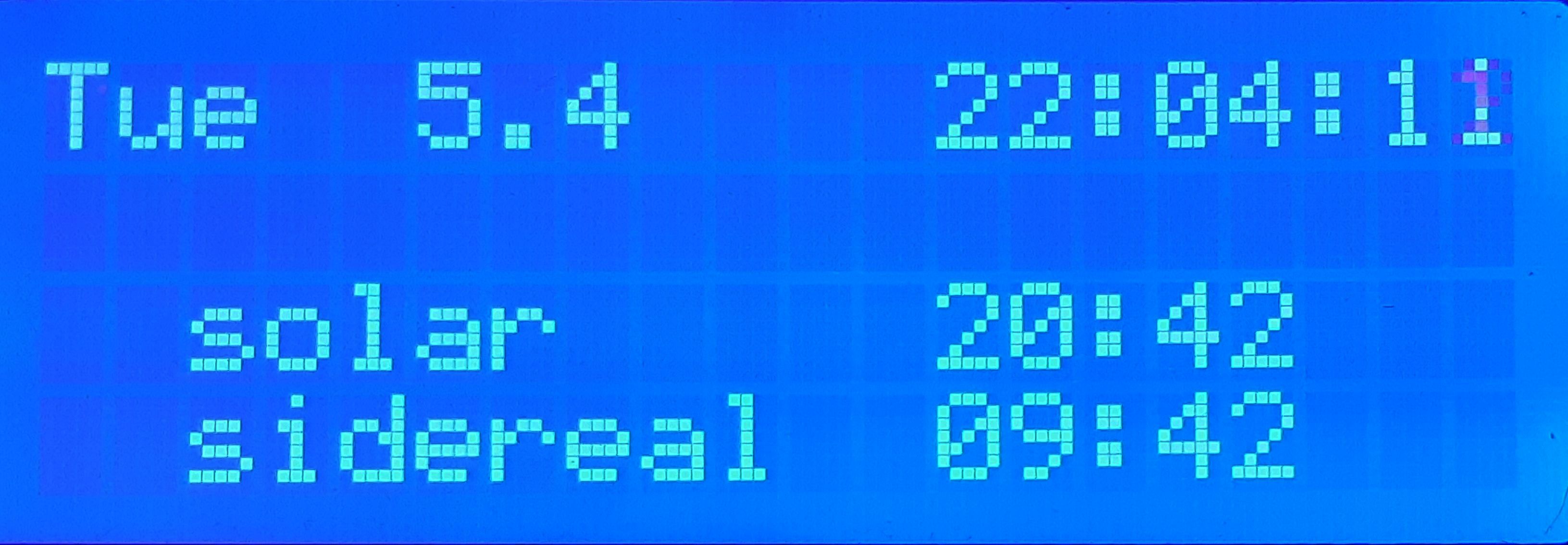
Version 1 of my Multi Face GPS Clock is here, as open source software for the Arduino Mega. It has some 22Β 19 different display screens showing time, location, solar and lunar positions and rise/set times. It shows UTC time as received from the GPS satellites and local time where it automatically adjust for summer time. The initial screen, no. 0, is this:

The display changes by pushing the right-hand pushbutton on the top, increasing the screen number by one. Similarly the number can be decreased by pushing the left-hand push-button. The potentiometer on the right side adjust the backlight. The clock is built on the same hardware as used for the K3NG Arduino CW keyer.

The date and time formats may be changed, and with US settings it looks like this:


This format is closer to the ISO standard:

When local time is shown, day names may be in another language than English. Here is my Norwegian day name display. The local short name for Tuesday (Tir) will be shown in some of the following displays also, because the native option is set:

The circuit diagram is rather simple and is based on an Arduino Mega and I2C or parallel connection to a 20x4 LCD display. It was drawn online on www.circuit-diagram.orgΒ and is a public circuit.

The GPS input is for serial data on a TTL-like interface. I use aΒ QRPLabs QLG1Β GPS. It is now discontinued and replaced by the QLG2.

The Menu+ and Menu- buttons will increase and decrease respectively the screen number in the following sequence of numbered screens.

The code is public on github.com/LA3ZA/Multi-Face-GPS-Clock. ItΒ uses 57714 bytes (22%) of program storage space of an Arduino Mega. This is too much to fit an Arduino Uno. Global variables use 2446 bytes (29%) of dynamic memory, leaving 5746 bytes for local variables.

Here are the other screens. Screen 1 shows UTC time and date, Maidenhead locator and number of satellites:

Screen 2 shows local time, and actual, civil, and nautical rise and set times for the sun, i.e. when the sun touches the horizon, and is 6 and 12 degrees below the horizon. To the right is shown solar elevation (-22 degrees), local time at solar noon (13.09), and solar elevation at local noon (27 degrees).

Screen 3 is similar to screen 2 except for the last line which shows the next lunar event, set, at 17:29, the lunar phase and illumination of, in this case, the decreasing moon, and lunar elevation.

Screen 4 is a lunar display showing actual elevation and azimuth, next set/rise time and azimuth. The last line shows lunar distance as a percentage of its maximum value (88-100%) and distance in km, as well as lunar phase (51% illumination).Β 

Screen 5 shows lunar rise/set times for the present 24 hours and the next and the corresponding azimuth angles:

Screen 6 is a display of time in various user configurable time zones, here showing central Europan Summer Time, Indian time, Eastern Daylight Time, and Pacific Daylight Time:

The following screens show several fancy, barely useable screens of various alternative displays. Screen 7 is binary while screen 8 is binary coded decimal:

Screen 9 is also binary coded decimal, but to be read vertically, like in the Wikipedia article on binary clock:Β 

Screen 10 is based on groups of three bars which are each 1/4 of a round clock:

Screen 11 emulates theΒ set theory clock in Berlin:Β 

Screen 12 emulates theΒ linear clock of Kassel:

Screens 13 and 14 are diagnostic displays which are not shown here. Screen 15 shows UTC time, position, altitude and number of satellites:

Screen 16 shows the NCDXF beacons in the 15, 12, and 10 m bands at the present time. It changes every 10 seconds as transmitters change frequency.

Screen 17 shows the NCDXF beacons in the 20, 17, and 15 m bands:

The NCDXF displays were inspired by the single-lineΒ display of OE3GOD.

Screen 18 shows the WSPR frequency used at the indicated time according toΒ coordinated band hopping. All 10 bands between 160 m and 10 m are covered in a 20 minute cycle:

After the last screen, the screen counter goes to 0 and the sequence is repeated as the right-hand button is pressed. Pressing the left-hand button will take you directly from the initial display to the WSPR screen.

The startup screen shows GPS baud rate (user settable) as it is waiting for a GPS signal:


The code is on github and has several options. The way to choose and set options has been inspired by the way it is done in the The K3NG Arduino CW Keyer.Β 

An important feature is that it is possible to customize which screens to show and in which order. Thus only screens 0-5 with time, solar and lunar positions and screens 16-18 with the NCDXF and WSPR sequences may be made available for instance.

Other options and features are:
  • FEATURE_LCD_I2CΒ  - I2C interface to LCD
  • FEATURE_LCD_4BIT - parallel interface to 20x4 LCDΒ 
  • FEATURE_DAY_NAME_NATIVE - to use local language day names for local time
  • SECONDS_CLOCK_HELP - to set the number of seconds per minute when time is shown in a normal format in the Binary, BCD, etc displays. Values from 0 (never) to 60 (always)
Date and time formats allow most of the formats found on the Date format page of Wikipedia:
  • DATEORDER = 'L': Little-endian:Β  22.04.2016 or 22.04 - EU
  • DATEORDER = 'M': Middle-endian:Β  04/22/2016 or 04/22 - US
  • DATEORDER = 'B': Big-endian:Β  Β  Β 2016-04-22 or 04-22 - ISO
  • DATE_SEP = '.'; // Alternatives: '.', '/', '–', ' ', ...
  • HOUR_SEP = ':'; // Alternatives: ':', '.', 'h', ...
  • MIN_SEPΒ  = ':'; // Alternatives: ':', '.', 'm', ...Β 

The GPS clock uses these libraries:
The lunar phase calculation is based on ideas discussed here. It is accurate to 5% or so compared to timedate.com.Β 

Details on how to set up the options and adaptations for the code published on github.com/LA3ZA/GPSClock is in the Wiki there.Β 


This blog post first appeared on the LA3ZA Radio & Electronics blog.

Finally figured out the moon

23 August 2021 at 16:10

I’ve been working on a GPS-controlled Arduino clock for some years and had set myself the goal of showing time for moonrise and for moonset for the present day. That turned out to be much harder than I had thought.

Finally, over the last few weeks I managed to adapt lunarCycle.c to Arduino and get it to work as shown in the display here. My ambition is now eventually to publish this project on GitHub as I’ve had several requests for it.

The display here shows local time and date, moon phase on line 2, present moon elevation and moon azimuth on line 3, and the next rise time of the moon and at which position on the final line. Follow label β€˜Arduino clock’ below for more posts about this clock.

Arduino bootloader burner

I have some spare ATmega328 chips that are not programed and can be used in some projects specially now the prices Arduino boards got some inflation.

In order to upload the program to the IC's you will need to burn first the bootloader, at least so that later you then upload via de Arduino IDE.Β 

Schematic and instruction are from here: https://docs.arduino.cc/built-in-examples/arduino-isp/ArduinoISP

End result:


Bottom Arduino is the programmer where you upload the ArduinoISP.ino code, it connects to the Arduino on top (target) that is going to have the chip to be programmed/burn.
The zif socket on the target Arduino just facilitates the insertion of the ATmega IC.

Another view:


For uploading: select the Arduino programmer USB port and then the programmer type "Arduino as ISP", in the end just "burn bootloader".


After bootloader burn:

Have a great day!


nanoBeacon: a simple personal CW beacon

4 October 2021 at 12:20

There are times when you wonder if your receiver and antenna are really working as they should. The band is dead, or empty, it’s the middle of the day, the D-Layer is sponging up every radio frequency excitation. Perhaps you can hear a few signals, but they are fleeting β€” and you need a steady and predictable signal source for a proper test. An RF signal generator will give you a steady carrier, but there are times when you’d prefer to have a true CW beacon to tune onto. This simple, general purpose multiband CW beacon can be run up on the frequency (or frequencies) of your choice, is powered on a 9V transistor radio battery, and can moved to attenuate to the desired signal level, for radio receiver system testing purposes.

This beacon transmits a hard-coded message in morse code on any frequency supported by the si5351 (10kHz to 160MHz). The code targets an Arduino Nano, Uno or bare ATMega328P and an si5351 breakout board. No display is necessary. You can add one, and controls, if you like. The code includes a simple CW keyer for manual sending (not used, but left in place for this application).

Any number of frequencies in the HF and VHF range can be specified by adding them to an array of transmit frequencies. The beacon iterates over the array and transmits the message on each frequency in sequence. The beacon’s CW speed is configurable. Sidetone is available as a 5v square wave on the D7 output. There is no support for switched low pass filters but this would be easy to add.

The Github repository is here.

❌
❌