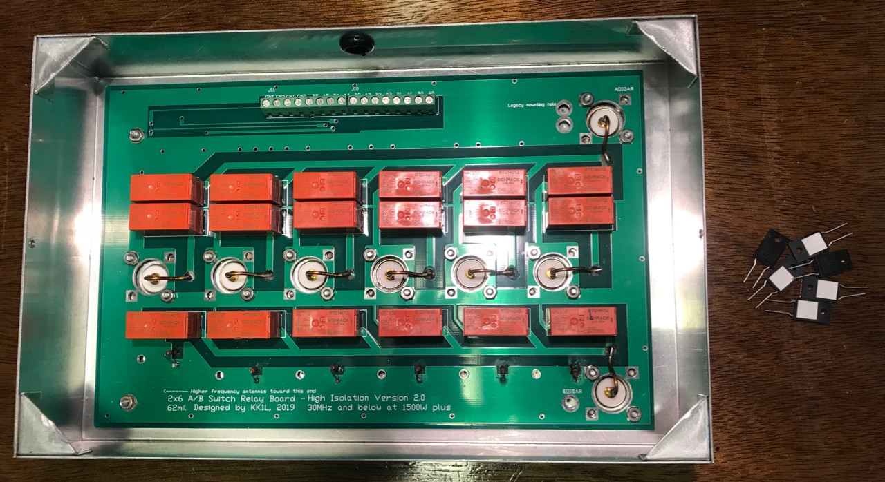
My KK1L board, showing the old resistors on the board, and the new ones on the desk.
While testing the KK1L Antenna Switch after mounting to the Single Point Ground (SPG), I noticed that some of the load resistors were no longer 50 ohms.
These resistors provide a load impedance whenever a antenna jack is not selected by either port A or Port B. This protects the antenna from static build-up as well as dissipating any coupled RF energy.
I originally used 50 ohm, 1/2 watt resistors I had on hand. Clearly they were not up to the task. On the ports for the shunt-fed tower, and the 80/40/20m trap dipole, these resistors were completely open. Both showed signs of overheating.
Most likely, these resistors succumbed to dissipating too much couple RF energy. I needed bigger ones. KK1L had 50 ohm, 50 watt resistors in his Mouser parts list, so that's what I ordered. These sorts of things come in handy, so I bought ten. Due to supply chain issues, they were back-ordered for months. But they finally arrived.
Replacing these parts is a pain. First, I had to remove the KK1L box from the SPG panel. Next, I had to remove the board from the aluminum box. Before I did that, I made sure to mark the locations the mounting screws for each resistor. To remove the board, I had to unsolder the eight connections to the SO-239 center conductors and bend them out of the way. Then came twenty-some nuts holding the board in place.
With the board separated from the box, I drilled the holes for the resistor mounting screws. I used a numbered drill bit the same size as the hole in the board to give me the largest tolerance. With the holes drilled and de-burred, my attention turned to the board.
Board with new resistors
Next step was to remove the existing resistors. Where they connect to the relays was easy, but the connections to the ground plane were harder. The ground plane tended to carry the heat away, making it hard to melt the solder without damaging the board. Getting these holes cleared of solder took a lot of effort.
Once done, the new resistors mount cleanly on the underside of the board. I oriented the resistors so the ceramic patch was toward the aluminum box. This patch does not appear electrically conductive.
After the resistors are soldered, the process is reversed to re-install the board in the aluminum box. In addition to the existing twenty-some nuts, there are also six new #4 screws and nuts to mount the resistors securely. With that in place, re-soldering the eight connections to the SO-239 center conductors completes the job.
I mounted the KK1L box to the SPG, and then re-tested all the switching combinations. This was to ensure I had connected the switching lines correctly.
I hope the new resistors are up to the job. I'll have to check on them in a few months to make sure.
As radio amateurs, taking proper precautions against lightning and electrical surges can be a difficult and expensive proposition. We often neglect them and rely on luck.
After reading Bonding and Grounding for the Radio Amateur, I decided it was worth the investment. I already had all ground connections - house, tower, station - bonded. What was missing was bonding the antenna connections to the ground as they entered the house. I needed a Single-Point Ground panel.
A Single-Point Ground is a metal panel or box providing a common bonding point for all cables as they enter a building. This metal is connected to the external ground rods, which are all bonded together. The idea is to bond the cables connected together, so that lightning or surge potentials all rise and fall together. Without a potential difference, damaging currents cannot flow.
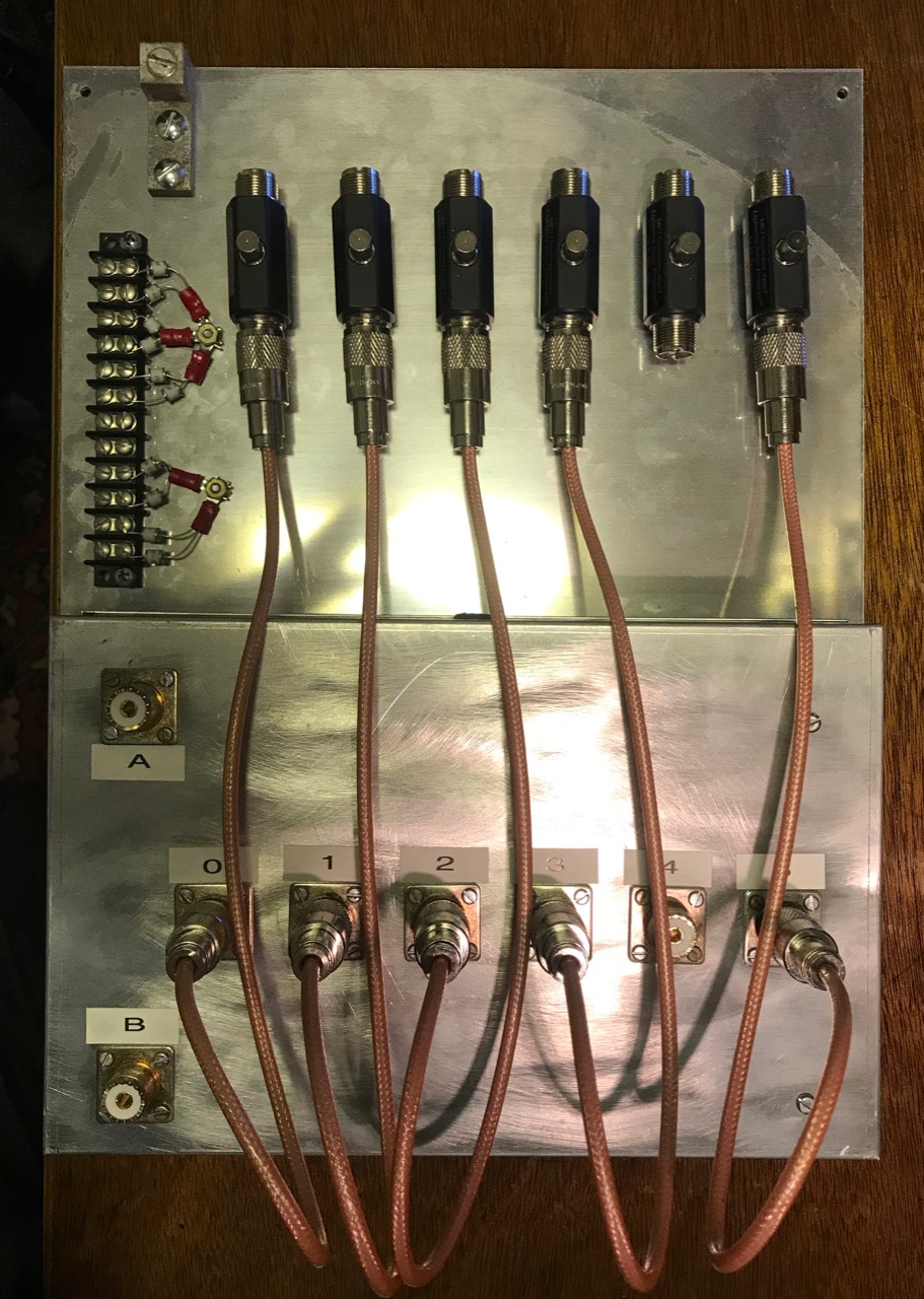
SPG panel ready to mount on basement wall
I cut a 0.090" Aluminum panel 12" by 16" and mounted the KK1L antenna switch to the bottom edge. I added lightning arrestors for the antenna coaxial cables, plus a barrier strip holding gas discharge tubes for the rotator and shunt antenna control cables.
I chose MFJ-272 lightning arrestors. I needed six of these, and the MFJ units were about $40 each. The Alpha Delta and Polyphaser units were more expensive. The arrestors are mounted to the panel with a single large screw, supplied with the arrestor.
Short coaxial jumpers connect the arresters to the KK1L switch. I made these out of 18 inches of RG-400 coax using new Amphenol UHF connectors and a UG-175 adapter. RG-400 is doubly-shielded, eliminating the potential for any coupling between the jumpers. (Notice I didn't quite have enough RG-400 for all six jumpers, so there are only five at the moment. I'll have to purchase more)
The panel mounts on the basement wall where the cables enter the house through a 4 inch PVC pipe. A grounding block connects a short piece of copper wire to an eight foot ground rod on the outside. The ground connection is also bonded to the perimeter ground wire between the house, tower and station grounds using a split bolt.
I had a bit of trouble with the coax running from the A and B ports of the KK1L to the operating desk. Since the coax to the antennas ended at the basement wall, I trimmed some coax from the antenna feed lines. To get the right length, I pulled the feed lines outside, then trimmed them from the far end. Simple, eh? Except the first one looped around and got stuck, and the cut piece ended up being about five feet too short.
The next feed line was a newer run of Davis Buryflex. I ran it to the A3S/A743, and then cut the right length. For some reason, I had problems with the connectors on both ends, but once they were redone, the cable worked as expected. For a short while, I thought the cable itself might be defective.
To do these tests, I made good use of my RigExpert AA-55 Zoom. Which of two pieces of old coax is any good? The cable loss test is quick and give one real numbers to compare. You just need to test the coax both open and shorted.
With the SPG installed, the next step is to automate the switching of the KK1L.
Cable management trays added to back of desktop selves.
Now that my station desktop is on wheels and has a set of nice shelves, I wondered might be done about the rats nest of wires hanging down from the back of the desk. Some kind of cable management system was needed.
These systems can be expensive. I found a solution on Amazon.com that worked pretty well. It is a kit of eight cable raceway trays about 15" long, 1.5" wide and just under 1" tall. All for just about $20.
These worked well with my desktop shelves. Three cable trays fit neatly on the back of the shelves just under the copper pipe ground bus bar. I mounted them using three short wood screws on each tray.
The tops of the trays either slide or snap off. The fingers on the sides are easily displaced to insert wires of just about any size. In some cases, cables are routed in the trays from one end of the shelves to the other.
From the picture, there are still a lot of wires, but it is neater and more manageable than before. Many of those are antenna coax or power connections. The antenna coax will be moving to the back wall of the basement once the Single-Point Ground (SPG) panel is in place.
I also improved the bonding between units. I'm using 1/2" tinned copper braid, a fork lug and a cable clamp around the 1/2" copper tube grounding bus. This creates a low-impedance connection between the equipment and the station ground. In a few cases, I had to drill a hole and add some #6 screws and nuts to make the connection.
The best part is, I still have five left-over cable management trays to use elsewhere.
Updated shelves as of January 2022. The AL-80A Amplifier is just off to the right side, on the desk.
Setting up my shack in my first home, in 1986, I needed to stack equipment. My operating position was a finished door on top of two filing cabinets, something that I used in my previous apartment. While the table was big enough, shelves were needed to easily access all my equipment.
I came up with a design using 1x12 lumber. There are three shelves, one 1", 12" and 22" above the tabletop. I chose these heights because it allowed me to slip my paper log books and other operating aids under the bottom shelf -- under the bottom row of gear.
I bought a stack of 1x12 boards, borrowed a friend's table saw and cut the pieces to length. I laid them on edge on the cement floor of my garage, glued the edges and pieced them together with wire brads. Everything lined up OK -- the result was pretty square.
35+ year old shelving unit, before it was removed from desk
The shelves were 48" wide ( 8 foot boards cut in half ), and had two uprights under each shelf. These shelves worked for several decades.
Over time, I noted problems. The upright supports limited the equipment I could put side by side, because only so much would fit. And the lowest shelf was problematic -- it meant my computer was in front of the shelf -- which meant my arms hung off the desk, with my forearms resting against the edge of the desk. This caused a lot of fatigue when contesting. Plus, I had stopped using paper logs back in 2006, so there was no reason for the lower shelf.
Micro-shack, before I moved.
I liked the layout I had back in the micro-shack. The desk surface was small (just a couple of inches wider than 5 feet), and the primary equipment sat on the desk itself, with other gear on a shelf. This meant I could re-position my gear at will. Best of all, the computer could be front and center, with my forearms resting comfortably on the desk itself.
After 35 years, the requirements came together. I needed a shelf unit with two shelves. The first shelf would be 12" above the desk, and the second shelf 22" above the desk. This left more than enough room to slide a 15-17" laptop under the bottom shelf. The shelves could be a little wider, to accommodate more equipment. Because my copper pipe grounding bar was a little more than 53" long, I opted to make the unit 52" wide.
I liked having the AL-80A amplifier on the right side of the desk, canted slightly to make the controls accessible, and allow for good cooling airflow. With a 52" wide self unit, this meant about 8" of unused desk space on the left-hand side. That was fine. That part of the desk is right next to a wall, and I don't put equipment that deep -- usually that's where my headphones and operating aides end up.
The bottom and top shelves would be separated by two uprights, with openings of roughly 17" on the left and right, and 15" in the middle. Under the bottom shelf, there would be no uprights. Instead, to keep the shelves from bowing, I used a piece of 1x4 as a sheer web at the back of the unit.
Here are the component dimensions used:
top (1x12) - 52”
shelf (1x12) - 50 1/2”
ends (1x12) - 21 3/4” (2)
separator (1x12) - 10” (2)
shear web (1x4) 50 1/2”
I bought the requisite 1x12 and 1x4 lumber, but didn't cut or assemble until later. This was unfortunate, because the lumber cupped a little bit as it dried out in my basement. This made the pieces a little harder to fit together. I used the same construction technique I used before -- glue and wire brads.
And even though I put the pieces together on my very flat workbench, a little bit of twist was introduced in the bottom shelf. It doesn't quite line up in the front like it should -- something I'll be looking at for the next 30+ years. I considered busting it apart and starting over, but I decided it would do as is.
Assembled unit with grounding bar installed
I intended to stain it and seal with polyurethane. However, I found that my stain had turned into a solid mass of jelly and was unusable. Instead, I applied three coats of polyurethane. The resulting finish is quite handsome.
The shelf unit is relatively light and quite sturdy. I'm sure it would support my weight, but I didn't try. The copper pipe grounding bar fastens to the 1x4. I use small hose clamps to attach wires to the grounding bar. This ensures that all gear is properly bonded to ground.
I'm very satisfied with the end result - plenty of room for gear on the desktop, with other gear on shelves at a handy height. The bits and pieces of equipment are slowly coming back to the operating desk, and I'm being careful in deciding what goes where -- it can get awfully cluttered.
I do love having a lot of space for computer gear on the desktop. I've had as many as three different laptops all running at the same time on the desk.
Now I've got to finalize where everything goes. I've already decided I need to move the P3, and the KK1L antenna switch matrix is going to end up on the basement wall on the Single-Point Ground panel.