I recently put up a 38m Inverted-L antenna (10m vertical/28m horizontal) and tuned it on the 160m band using a home-brew Pi-Network ATU. It’s working great on top band and I’m really pleased with performance so far.
I decided today that it would be good to try the inverted-L out on some of the other low bands too. Since my other HF antenna is a large vertical that’s great for DXing but, terrible for Inter-G I thought perhaps the Inverted-L would fill the inter-G gap.
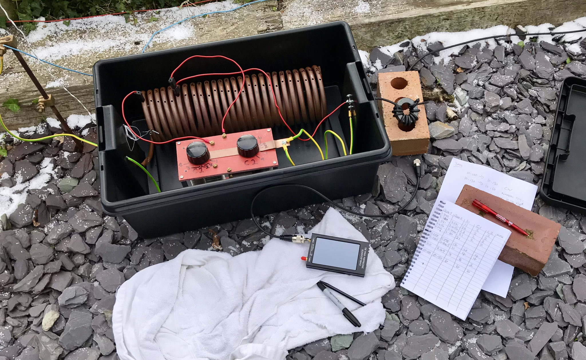
M0AWS Pi-Network ATU using my JNCRadio VNA to find the ATU setting for each band
Having recently purchased a JNCRadio VNA from Martin Lynch and Sons it made tuning the ATU for each band really easy. When it comes to antenna resonance I like my antennas to have an SWR of less than 1.2:1. With the VNA connected it is really easy to tune the antenna for a 1:1 SWR on a particular frequency, make a note of the tune information and then move to the next frequency and start again.
M0AWS Pi-Network ATU Inductor with turns countM0AWS Pi-Network ATU Capacitor 1 and 2 settings
I marked up each turn on the large copper inductor so I could record the position of the input wire onto the inductor. I then added some markings on the two capacitors of the Pi-Network ATU for the resonance points on each band/frequency I wanted to resonate the antenna on.
M0AWS Pi-Network ATU settings noted for each band
After about 40mins I had all the settings recorded on a pad ready for testing from the shack end of the coax run. Connecting my Yaesu FTDX10 to the coax I ran through each band setting checking the SWR as I went. All bands tuned up perfectly 160m through 30m and receiving of Inter-G on the bands that were active was excellent.
Wanting to test the antenna on 40m for the first time I found Nick, M7NHC calling CQ and gave him a call using just 5w output. He came straight back to me and we had a quick chat.
Nick was using an Icom IC-7300 using just 10w into an end-fed long wire from Eastbourne down on the south coast so, we were both QRP. Nick was a 5/7 with QSB and he gave me a 5/8 with QSB, not bad at all consider how much power we were using.
I’m hoping to have a chat with some of the guys from the Matrix this evening on 60m SSB so, it will be interesting to see how the antenna performs on 5Mhz.
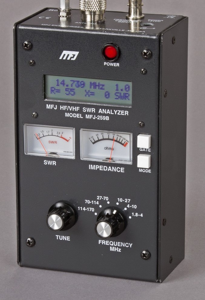
Many years ago I had an MFJ-259B antenna analyser that I used for all my HF antenna projects. It was a simple device with a couple of knobs, an LCD display and a meter but, it provided a great insight into the resonance of an antenna.
MFJ-259B Antenna Analyser
Today things have progressed somewhat and we now live in a world of Vector Network Analysers that not only display SWR but, can display a whole host of other information too.
Being an avid antenna builder I’ve wanted to buy an antenna analyser for some time but, now that I’m into the world of QO-100 satellite operations using frequencies at the dizzy heights of 2.4GHz I needed something more modern.
If you search online there are a multitude of Vector Network Analysers (VNAs) available from around the £50.00 mark right up to £1500 or more. Many of the VNAs you see on the likes of Amazon and Ebay come out of China and reading the reviews they aren’t particularly reliable or accurate.
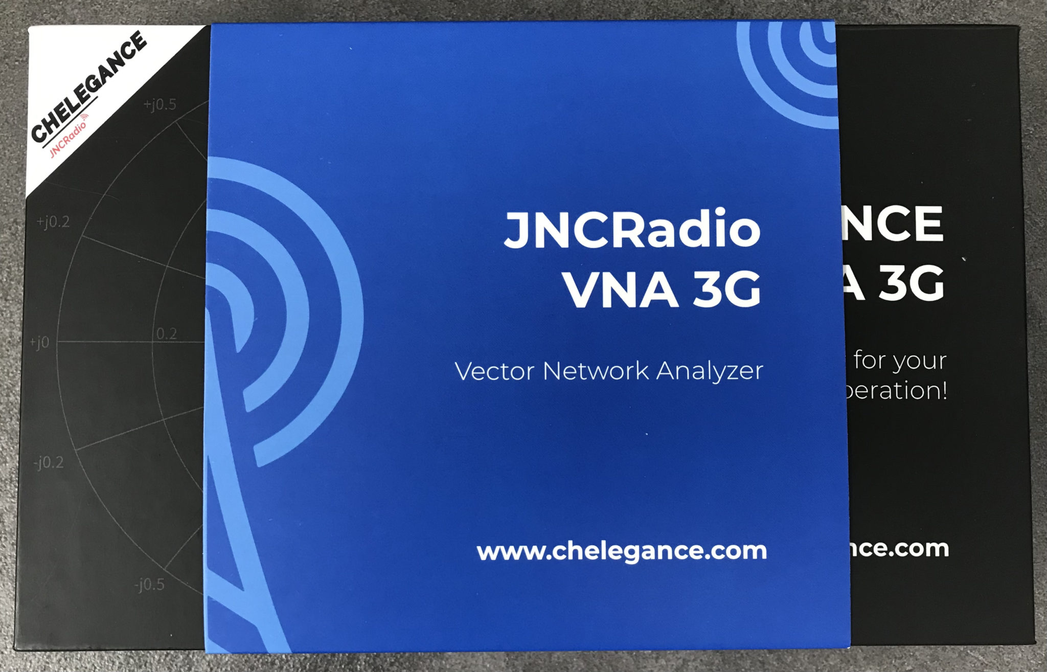
After much research I settled on the JNCRadio VNA 3G, it gets really good reviews and is very sensibly priced. Putting a call into Gary at Martin Lynch and Sons (MLANDS) we had a long chat about various VNAs, the pros and cons of each model and the pricing structure. It was tempting to spend much more on a far more capable device however, my sensible head kicked in and decided many of the additional features on the more expensive models would never get used and so I went back to my original choice.
Gary and I also had a long chat about building a QO-100 ground station, using NodeRed to control it and how to align the dish antenna. The guys at MLANDS will soon have a satellite ground station on air and I look forward to talking to them on the QO-100 transponder.
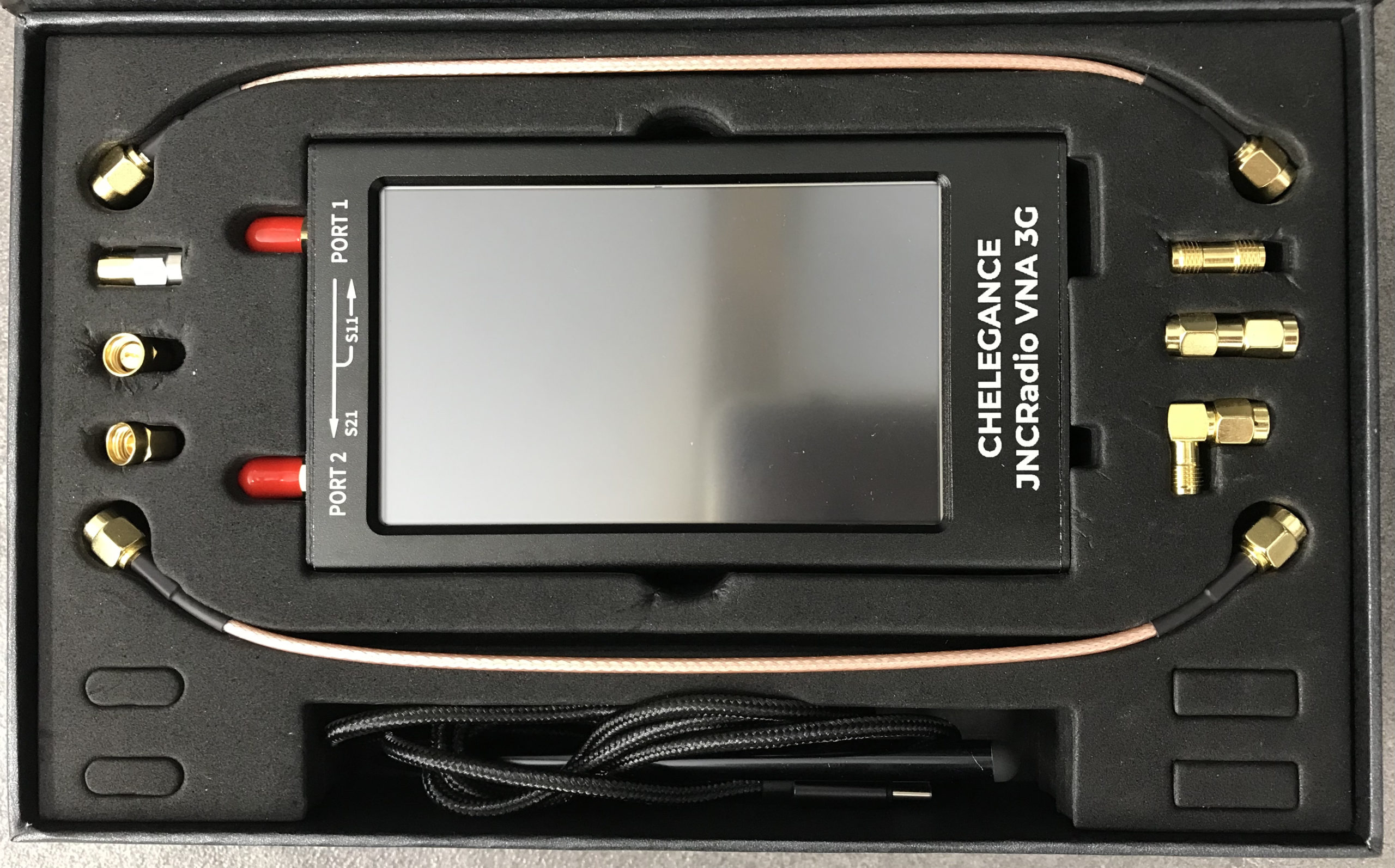
M0AWS – JNCRadio VNA 3G PackagingM0AWS – JNCRadio VNA 3G in box with connectors and cables
Initially I wanted to check the SWR of my QO-100 2.4GHz IceCone Helix antenna on my satellite ground station to ensure it was resonant at the right frequency. Hooking the VNA up to the antenna feed was simple enough using one of the cables provided with the unit and I set about configuring the start and stop stimulus frequencies (2.4GHz to 2.450GHz) for the sweep to plot the curve.
The resulting SWR curve showed that the antenna was indeed resonant at 2.4GHz with an SWR of 1.16:1. The only issue I had was that in the bright sunshine it was hard to see the display and impossible to get a photo. Setting the screen on the brightest setting didn’t improve things much either so this is something to keep in mind if you plan on using the device outside in sunny climates.
(My understanding is that the Rig Expert AA-3000 Zoom is much easier to see outside on a sunny day however, it will cost you almost £1200 for the privilege.)
A couple of days later I decided to check the SWR of my 20m band EFHW vertical antenna. I’ve known for some time that this antenna has a point of resonance below 14MHz but, the SWR was still low enough at the bottom of the 20m band to make it useable.
Hooking up the VNA I could see immediately that the point of resonance was at 13.650Mhz, well low of the 20m band and so I set about shortening the wire until the point of resonance moved up into the band.
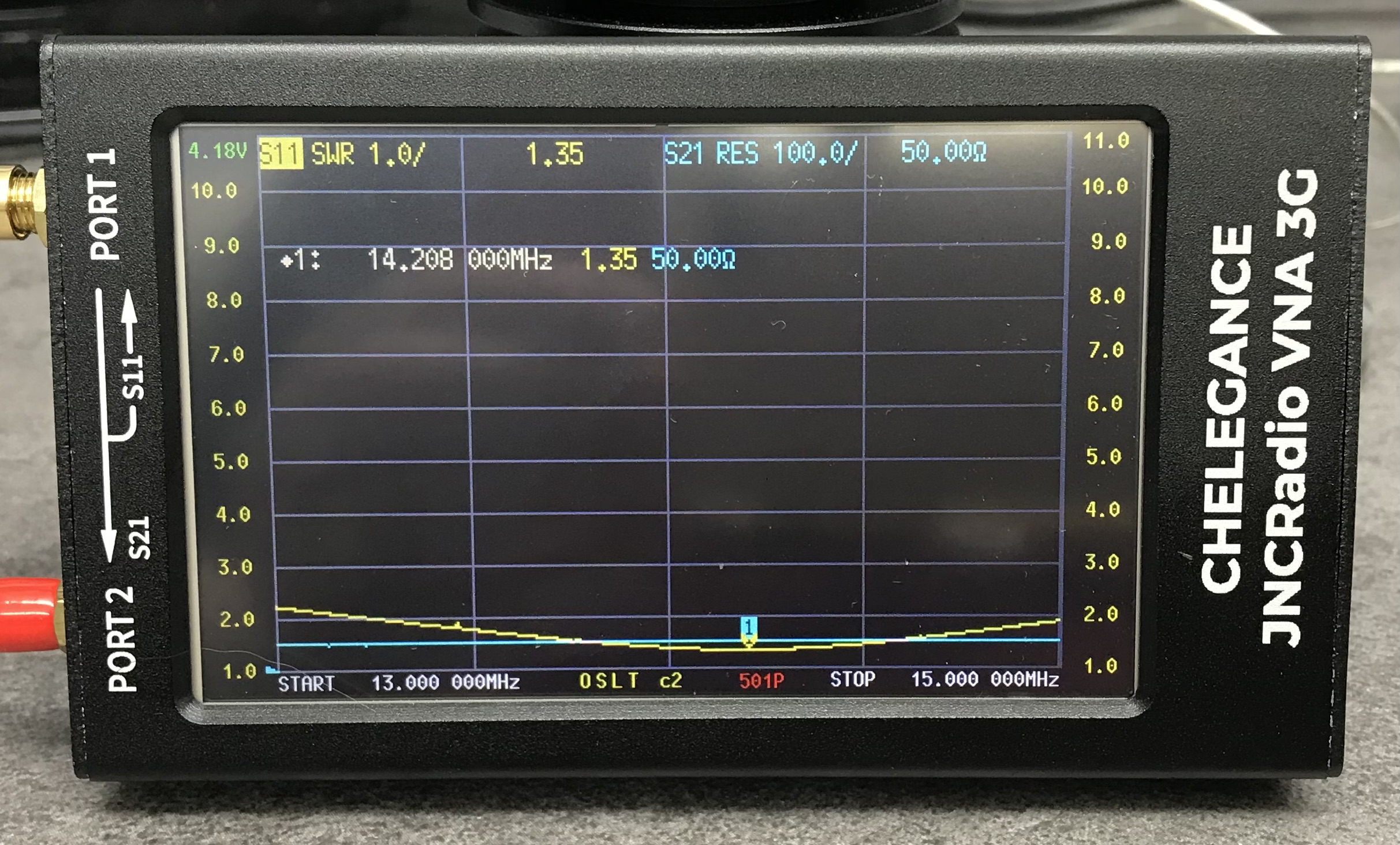
JNCRadio VNA3G showing 20m Band EFHW Resonance
With a little folding back of wire I soon had the point of resonance nicely into the 20m band with a 1.35:1 SWR at 14.208Mhz. This provides a very useable SWR across the whole band but, I decided I’d prefer the point of resonance to be slightly lower as I tend to use the antenna mainly on the CW & FT4/8 part of the band with my Icom IC-705 QRP rig.
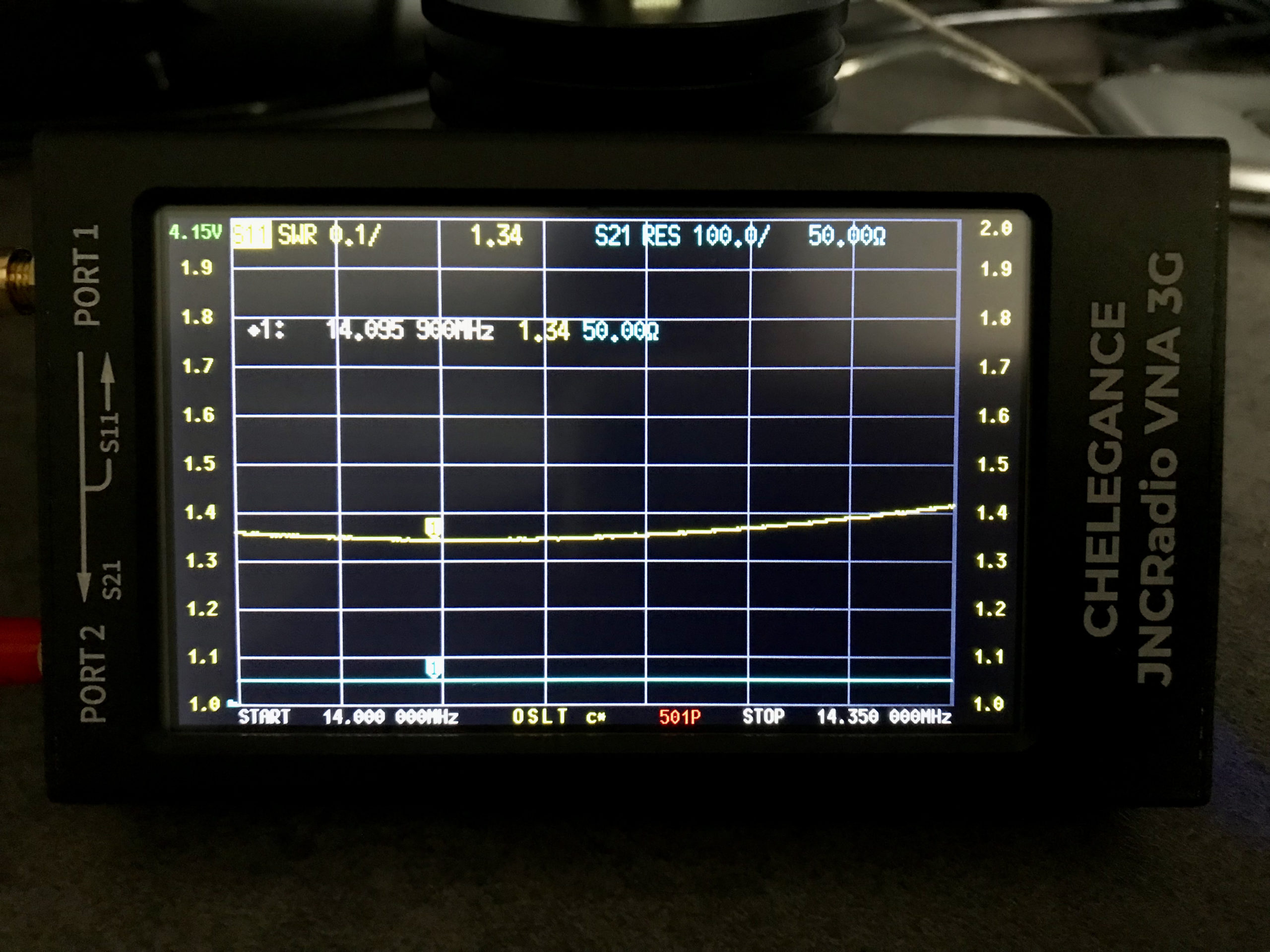
Popping out into the garden once more I lengthened the wire easily enough by reducing the fold back and brought the point of resonance down to 14.095Mhz.
JNCRadio VNA3G showing 20m Band EFHW Resonance 14Mhz to 14.35Mhz Sweep
The VNA automatically updated the display realtime to show the new point of resonance on the 4.3in colour screen. I also altered the granularity of the SWR reading on the Y axis to show a more detailed view of the curve and reduced the frequency range on the X axis so that it showed a 14Mhz to 14.35Mhz sweep. With an SWR of 1.34:1 at 14.095Mhz and a 50 Ohm impedance, the antenna is perfectly resonant where I want it.
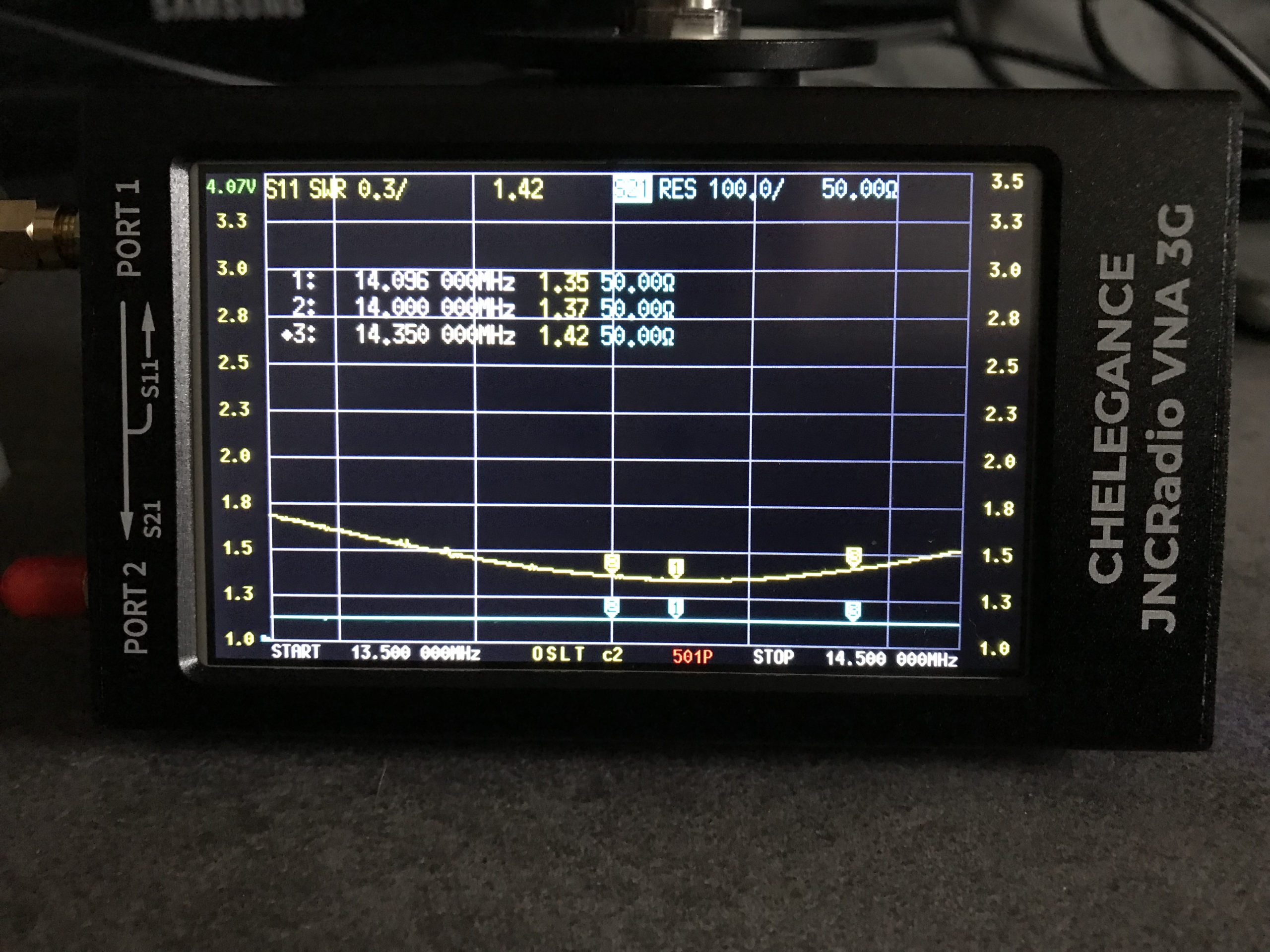
It’s interesting to note that the antenna is actually useable between 13.5Mhz and 14.5Mhz with a reasonable SWR across the entire frequency spread. Setting 3 markers on the SWR curve I could see at a glance the SWR reading at 14Mhz (Marker 2) , 14.350Mhz (Marker 3) and the minimum SWR reading at 14.095Mhz (Marker 1).