Please join us this evening, from 7PM – 9PM at the Cumberland County EMA Bunker, located at 22 High Street, in Windham, ME, for our monthly Emergency Communications Team (ARES) meeting.
Tonight we’ll be discussing the upcoming Simulated Emergency Test, which takes place Saturday, October 26th.
For those who won’t be able to join us in person, please tune in to our ECT training net on the 449.225 (- / 103.5 Hz) WS1EC repeater at 7PM.
This month, we will also be testing Simplex coverage, after the net on the repeater, on 146.580.
The 6 meter band is hot in the summer time and there is no better way to exploit it than with a directional antenna like the 6 meter Moxon. The Moxon is a 2 element Yagi that is inexpensive and easy to build, but also offers great results with 5.5dbi of gain and a 25db front to back ratio
The Moxon is named after its creator Les Moxon, G6XN. It is best described as a rectangular two element Yagi antenna. I said rectangular as the ends of the driven element and the reflector are folded inwards, which reduces the amount of space it occupies, about 70% of the space of an equivalent dipole antenna. If you add lightweight spanners to the rectangle, you can rotate the antenna.
Typically, a 6 meter Moxon will have about 5.5dbi of forward gain, and exhibit a high front to back ratio, up to 25 dbi when elevated to the optimal height of about 18 feet. They also have a 50 ohm impedance at the feed point, so no matching network is required, which simplifies their construction.
To make this project more approachable, three of the parts are 3D printed, the hub, hub adapter, and feed point mount. I used PLA+ to print these parts. This is ok for temporary use, but if you are thinking of permanently mounting this antenna, I’d use something more weather resistant like Petg or ASA. All of my 3D printed parts are available on Thingaverse if you want to tackle this project yourself.
The KB9VBR 6 Meter Moxon Antenna Parts list: 4 – 48 inch x 3×8 inch fiberglass fence posts 1 – 3D printed Moxon hub 1 – 3D printed hub adapter 1 – 3D printed Feedpoint center SO-239 chassis connector 20 feet 20 or 22 ga wire 6 x ½ inch machine screws, nuts, and washers 8 small Ring terminals String trimmer line Painters pole: 15 – 23 feet
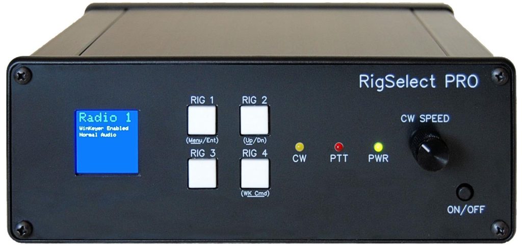
OnAllBands has exciting news for multi-operator contest stations. DX Engineering now carries the RigSelect Pro Transceiver Switch and SO2R Controller—a device loaded with advanced features for contesters looking for a competitive edge.
The RigSelect Pro makes it possible to implement a station in which any two of up to four connected radios can be selected as the SO2R pair—and in any order. Further, users can switch one set of headphones, microphone, paddle/key, and PTT line among any of four radios.
Contesters can enjoy quiet, solid-state, telcom-quality relays for all audio switching, which makes switching extremely fast. Status and menu options can be clearly viewed on a color TFT display. The compact unit (2.83″ H x 7.72″ W x 6.69″ D) tips the scales at only 2.76 pounds.
(Image/DX Engineering)
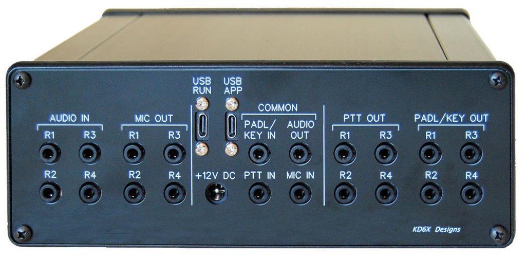
The RigSelect Pro supports OTRSP (Open Two Radio Switching Protocol) directly. Multiple configurations of SO2R audio management are available depending on operator preferences. Key, microphone, and PTT can be quickly switched between any two of up to four connected radios under control of a logging program using the OTRSP protocol.
(Image/DX Engineering)
There are three logical serial ports available for computer control of the RigSelect Pro via two physical USB-C connectors:
On the RUN USB connector, one port is for CW commands to the built-in genuine K1EL WinKeyer 3 CW chip.
A second port connects a logging program to RigSelect Pro using OTRSP to make lightning-fast computer-controlled transitions between radios. Because of these two ports on the RigSelect Pro, an interface program is not required on a PC. Connection can be made directly between most logging programs and the two CW/OTRSP ports.
A third port on the APP USB connector is available for the Windows RigSelect Application for Microsoft Windows. This allows the operator direct control of RigSelect Pro via a Windows interface for quick adjustment of RigSelect Pro options and settings without using the front panel menu system.
The RigSelect Pro also supports a powerful computer control capability via an internal command set which is available on the APP connector. In addition to all the OTRSP commands, there are 65 different RigSelect commands available. These can be combined in a macro for use either within the App or assigned to a front panel pushbutton. In addition to the above features and the OTRSP protocol, RigSelect implements the audio switching capabilities popularized in the YCCC SO2R Box as listed below with some improvements.
Blank TX on XMIT: This is an SO2R option to blank the audio from the radio that is transmitting a computer-generated message.
Blank with Blend: Blend is also available in the Blank TX on XMIT option. This allows a lower volume audio signal from the transmitting radio to still be heard in that radio’s earpiece. The volume level of the Blend can be set using the “Blend Volume” setting.
Split-Latch Option: This is an SO2R option where both earpieces are switched to the tip (left) main receiver channel of the receiving radio while the other radio is transmitting under computer control.
Split-Stereo: In Split-Stereo, both earpieces are switched to the receiving radio stereo outputs during transmit. Once transmit is concluded, the headphones will be returned to the radios they were connected to prior to transmit.
Standard SO2R: This is not a specific option but is the result of not selecting any of the other transmit radio audio switching options. This is also the factory default. In other words, “Standard SO2R” is what you get when Split-Latch, Split-Stereo, and Blank-on-TX are all turned off. In this case, nothing happens to headset audio when transmit is occurring. You continue to hear the transmitting radio in its assigned earpiece. This will usually be a sidetone or monitor signal.
For more details about the RigSelect Pro, watch Tim Duffy, K3LR, interview Courtney Krehbiel, KD6X, owner of KD6X Designs, in the video below:
At the end of last week, we posted how SDRplay released the RSPdx-R2, an updated version of their RSPdx product. Recently Matt from the Tech Minds YouTube channel received his RSPdx-R2 and has uploaded a video comparing the RSPdx-R2 to the previous model. His results show that the new model has an improved lower noise floor, resulting in signals with higher SNR.
In his tests, Matt uses the SDR Connect Preview 3 software. This is the latest version of SDRplay's new custom multiplatform software that they are developing. While testing the RSPdx-R2, Matt allows shows some of the new features in SDR Connect Preview 3, including a new Audio peak hold graph, FM MPX view, and a new frequency manager.
I’ve got a couple of old RaspberryPi computers on the shelf in the shack and so decided it was time for me to put one of them to good use. The first model on the shelf is the oldest and is one of the very first RaspberryPi 1 computers that was released. (It’s the one with the yellow analog video signal output on the board!). This particular model is extremely slow but, I hang onto it just as a reminder of the first SBC in the line.
The second one is a RaspberryPi 2, a quad core machine that is only slightly faster than the first model but, it’s powerful enough to run HAM Clock.
It didn’t take long to install a vanilla Raspbian Desktop O/S and get it configured on the local LAN. I installed a few packages that I like to have available on all my Linux machines and then started on the HAM Clock install.
The first thing I needed to do was install the X11 development library that is required to compile the HAM Clock binary. To do this, open a terminal and enter the command below to install the package.
sudo apt install libx11-dev
You will need to type in your password to obtain root privileges to complete the installation process and then wait for the package to be installed.
The HAM Clock source code is available from the HAM Clock Website under the Download tab in .zip format. Once downloaded unzip the file and change directory into the ESPHamClock folder ready to compile the code.
cd ~/Downloads/ESPHamClock
Once in the ESPHamClock directory you can run a command to get details on how to compile the source code.
make help
This will check your system to see what screen resolutions are available and then list out the options available to you for compiling the code as shown below.
The following targets are available (as appropriate for your system)

    hamclock-800x480          X11 GUI desktop version, AKA hamclock
    hamclock-1600x960         X11 GUI desktop version, larger, AKA hamclock-big
    hamclock-2400x1440        X11 GUI desktop version, larger yet
    hamclock-3200x1920        X11 GUI desktop version, huge

    hamclock-web-800x480      web server only (no display)
    hamclock-web-1600x960     web server only (no display), larger
    hamclock-web-2400x1440    web server only (no display), larger yet
    hamclock-web-3200x1920    web server only (no display), huge

    hamclock-fb0-800x480      RPi stand-alone /dev/fb0, AKA hamclock-fb0-small
    hamclock-fb0-1600x960     RPi stand-alone /dev/fb0, larger, AKA hamclock-fb0
    hamclock-fb0-2400x1440    RPi stand-alone /dev/fb0, larger yet
    hamclock-fb0-3200x1920    RPi stand-alone /dev/fb0, huge
For my system 1600×960 was the best option and so I compiled the code using the command as follows.
make hamclock-1600x960
It’s no surprise that it takes a while to compile the code on such a low powered device. I can’t tell you how long exactly as I went and made a brew and did a few other things whilst it was running but, it took a while!
Once the compilation was complete you then need to install the application to your desktop environment and move the binary to the correct directory.
make install
Once the install is complete there should be an icon on the GUI desktop to start the app. If like mine it didn’t create the icon then you can start the HAM Clock by using the following command in the terminal.
/usr/local/bin/hamclock &
The first time you start the app you’ll need to enter your station information, callsign, location etc and then select the settings you want to use. There are 4 pages of options for configuring the app all of which are described in the user documentation.
M0AWS – HAM Clock running on RaspberryPi Computer
Once the configuration is complete the map will populate with the default panels and data. I tailored my panels to show the items of interest to me namely, POTA, SOTA, International Beacon Project and the ISS space station track. I was hoping to be able to display more than one satellite at a time on the map however, the interface only allows for one bird to be tracked at a time.
You can access the HAM Clock from another computer using a web browser pointed at your RaspberryPi on your local LAN using either the IP address or the hostname of the device.
http://<hostname>:8081/live.html

or

http://<ip-address>:8081/live.html
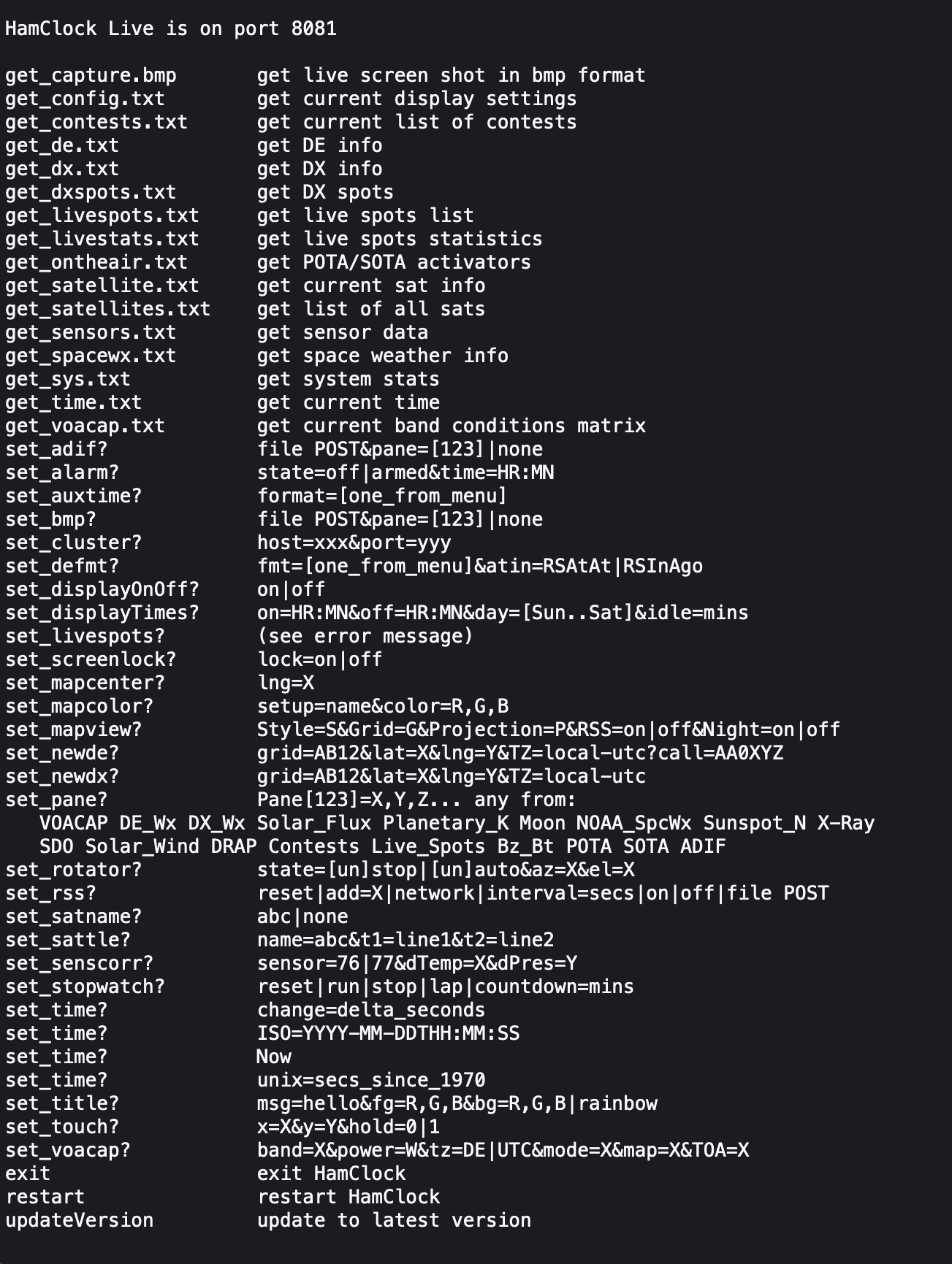
You can also control the HAM Clock remotely via web browser using a set of web commands that are detailed on port 8080 of the device.
http://<hostname or ip-address>:8080/
M0AWS – HAM Clock remote command set
This is a great addition to any HAM shack especially if, like me you have an old HDTV on the wall of the shack that is crying out to display something useful.
Figure 1: Close-in responses of various filter combinations Yellow: Duplexer-only Magenta: Bandpass-only Cyan: Duplexer + Bandpass Click on the image for a larger version.
There is a follow-up article to this one - "A simple VHF notch cavity from scraps of (large) heliax" - link.
The case for bandpass filtering
If you operate a repeater - or even a simplex radio such as a Packet node - that is located at a "busy" radio site, you'll no doubt be aware of the need for cavity-based filtering.
In the case of a repeater, the need is obvious: Filtering must be sufficiently "strong" to keep the transmit signal out of the receiver, and also to remove any low-level noise produced by the transmitter that might land on the receive frequency.
In the case of a packet or simplex node of some sort, a simple "pass" cavity is often required at a busy site to not only prevent its receiver from being overloaded by off-frequency signals, but also be a "good neighbor" and prevent low-level signals from your transmitter from getting into other users' receivers - not to mention the preventing of those "other" signal from getting back into your transmitter to generate spurious signals in its own right.
Comments:
In this discussion, a "band pass" filter refers to the passing of ONLY a narrow range of frequency near those of interest and at odd multiples of the lowest resonant frequency - but nothing else.
It is HIGHLY RECOMMENDED that anyone attempting to construct this type of filter get and learn to use a NanoVNA: Even the cheapest units (approximately $50US) - when properly set up - will be capable of the sorts of measurements depicted in this article.
A Band-Pass/Band-Reject (BpBr) duplexer may not be what you think!
A common misconception is that a typical repeater duplexer - even though it may have the words "band pass" written on its label or in its specifications - has a true "band pass" response.
Figure 1 shows a typical example of this fallacy. The yellow trace shows the response of a typical 2 meter duplexer where we can see a peak in response at the "pass" frequency and a rather deep notch at the frequency that we wish to reject.
The problem becomes more apparent when we look over a broader frequency range. Figure 2 shows the same hardware, but over a span of about 30 MHz to 1 GHz.
Figure 2: The same as in Figure 1 except over a wider frequency range showing the lack of off- frequency rejection of a "BpBr" duplexer (Yellow) that is significantly mitigated by the addition of a band-pass filter (Cyan) Click on the image for a larger version.
Keeping an eye on the yellow trace, you'll note that over most of the frequency range there is very little attenuation. What this means is that the "BpBr" filter doesn't exhibit a true pass response once you get more than a few MHz away from the design frequency.
I've actually had arguments with long-time repeater owners that disagreed with this assertion, but hadn't actually "swept" a duplexer over a wide frequency range: These days, with the availability of inexpensive test equipment like the NanoVNA, there's no good excuse for not determining this for yourself!
For more about this, see the related articlelinked here.
Why is this a problem?
In the "old days" radios that you would use at a repeater site were typically cast-off mobile radios - and even if you had a repeater, it was typically based on a mobile design. These older radios - often from the 80s or earlier - typically used a bank of narrowband (often Helical) filter elements, each tuned to the frequency of interest: If several frequencies were used, the system planners often placed then near each other so that they could be covered by the receivers' narrow filters without undue attenuation and because of this, one could "get away with" a duplexer with filtering that didn't offer a "true" pass-band response.
Most modern radios used in amateur repeaters are "broadband" in nature meaning that they often have rather wide receiver front-end filters: It is not practical to have electronically-tuned filters that are anywhere near as narrow as the Helical filters of the past which means that they simply lack the filtering to reject strong, off-frequency signals.
The poor filtering of some "new" radios:
When a modern radio is dropped in place of an old radio at a "busy" site with lots of other transmitters, disappointment is sometimes the result: The "new" radio may seem less sensitive than the old one - or it might seem that sensitivity varies over time. In reality, the "new" radio may well be being overloaded by the off-frequency signals that the old radio's resonator-based front-end easily filtered. What's worse is that the precise nature of this overload condition may be masked by the use of subaudible tones or digital tone squelch - and if this is a digital radio system like D-Star, Fusion or DMR, there may be no obvious clues at all as to the problem at hand unless one has the ability to measure and monitor the analog "baseband" from the receiver itself.
To be sure, if the receiver in question can operate in carrier-squelch analog mode, the usual techniques to determine overload (Iso-Tee measurements, injection of a weak carrier and observing SNR, etc.) may be employed to determine if there is an issue - but this, too, may be misleading as problems may be intermittent, showing up only when a combination of transmitters key up.
A simple pass cavity:
While not a panacea, the use of a simple pass-only cavity can go a long way to diagnose - even solve - some chronic overload issues - particularly if these have arisen when old gear was replaced. Suitable pass cavities are readily available for purchase new from a number of suppliers and used from auction sites - they are also pretty easy to make from copper and aluminum tubing - if you have the tools. Because of the rather broad nature of a typical pass cavity, temperature stability is usually not much of an issue in that its peak could drift hundreds of kHz and only affect the desired signal by a fraction of a dB.
Another material that could be used to make reasonable-performance pass cavities is larger-diameter hardline or "Heliax" (tm). Ideally, something on the order of 1-5/8" or larger would be used owing to its relative stiffness and unloaded "Q" and either air or foam dielectric cable may be used, the main difference being that the "Q" of the foam cable will be slightly lower and the cavity itself will be somewhat shorter.
Figure 3: Cutting the (air core) cable to length Click on the image for a larger version.
The "Heliax bandpass cavity" described here can be built with simple hand tools, and it uses a NanoVNA for tuning and final adjustment. While its performance will not be as good as a larger cavity, it will - in many cases - be enough to attenuate strong, out-of-band signals that can degrade receiver performance.
Using 1-5/8" "Heliax":
The "cavity" described uses 1-5/8" air-core "Heliax" - and it is necessary for the inner conductor to be hollow to accommodate the coupling capacitors. Most - but not all - cable of this size and larger has a hollow center conductor. Cables larger diameter than 1-5/8" should work fine - and are preferred - but smaller than this may not be practical - both for reasons of unloaded "Q" and also if the center conductor is solid or if its inside diameter cannot accommodate the coupling capacitors described later on.
Note: The KF6YB article linked below contains some length calculators for coaxial cable.
Preparing the "shorted" end:
For 2 meters, a piece of cable 18" long was cut. For the air dielectric, it's recommended that one cuts it gently with a hand saw rather than a power tool as the latter can "snag" and damage the center conductor.
Figure 4: The "shorted" end of the stub with the slits bent to the middle and soldered to the center conductor. Click on the image for a larger version.
For the "cold" (e.g. shorted) end, carefully (using leather gloves) remove about 3/4" (19mm) of the outer jacket and then clean the exposed copper shield with a wire brush, abrasive pad and/or sand paper. With this done, use a pair of tin snips cut slots about 1/2" (12mm) deep and 1/4" (6mm) wide around the perimeter. Once this is done, use a pair of needle nose pliers and remove every other tab, resulting is a "castellated" series of slots. At this point, using a pair of diagonal pliers or a knife, cut away some of the inner plastic dielectric so that it is about 1/2" (12mm) away from the end of the center conductor.
Now, clean the center conductor so that it is nice and shiny and then bend the tabs that were cut inwards so that they touch the center conductor. Using a powerful soldering iron (I used a 150 watter) or soldering gun - and, perhaps a bit of flux - solder the shield tabs to the center conductor all of the way around. It's best to do this with the section of coax laying on its side so that hot solder/metal pieces do not end up inside the coax - particularly if air-core cable is used. If you used acid-core flux, carefully remove it before proceeding.
With one end of the cable shorted you can trim back any protruding center conductor and file any sharp edges - again taking care to avoid getting bits of metal inside the cable or embedded in the foam. At some point, you should cover the shorted end with RTV (silicone) and/or good-quality electrical tape to prevent contamination by dust or insects.
Preparing the "business" end:
Figure 5: The "coupling tubes" soldered in place which receive the wires for coupling in/out. Click on the image for a larger version.
At this point, the chunk of coax should be trimmed again, measuring from the point where the center conductor is soldered to the shield: For air-core trim it to 17" (432mm) exactly and for foam core, trim it to 16-1/8" (410mm). Again, using a sharp knife and gloves, remove about 3/4" (19mm) of the outer jacket and, again, clean the outer conductor so that it is bright and shiny.
Making coupling capacitors:
We now need to make two capacitors to couple the energy from the "in" and "out" connectors to the center resonator and for this, I cut two 3" (75mm) long pieces of RG-6 foam TV coaxial cable and from each of these pieces, I removed and kept the center conductor and dielectric - removing any foil shield and then stripping about 1/2" (12mm) of foam from one end of each piece.
At this point, you'll need some small copper tubing: I used some 1/4" O.D. soft-drawn "refrigerator" tubing, cutting two 2" (50mm) lengths and carefully straightening them out. To cut this, I used a rotary pipe cutting tool which slightly swedged the ends - but this worked to advantage: As necessary, I opened up the end cut with the deburring blade of the rotary cutting tool just enough that it allowed the inner dielectric of the RG-6 to slide in and out with a bit of friction to hold it in place..
Comment:
The use of 1/4" (6mm) O.D. copper pipe and RG-6 center conductor/dielectric isn't terribly critical: A different-sized copper or brass pipe could be used as long as two parallel pieces will fit inside the center conductor of the Heliax - and that the chosen center conductor and dielectric of the coax you use to make the capacitor will fit somewhat snugly inside it.
The reason for the two copper tubes is to prevent the two capacitors made from the center of the RG-6 from coupling directly to each other as all energy must first resonate the center conductor. Using these tubes - soldered to the center conductor/resonator - prevents such direct coupling, and it offers good mechanical stability.
Figure 6: The PC Board plate soldered to the end of the coax. Click on the image for a larger version.
Using a hot soldering iron or gun, solder the two straightened pieces of tubing together, in parallel, making sure that the ends of the tubing that you adjust to snugly fit the outside diameter of the piece of RG-6 are at the same end. Once this is done, insert the two parallel pieces of tubing inside the Heliax's center conductor and solder them, the ends flush with the end of the center conductor, taking care not to heat them enough that they unsolder from each other: A pair of sharp needle-nose pliers to hold them in place is helpful in this task.
Making a box:
On the "business" (non-shorted) end of the piece of cable we need to make a simple box with a solid electrical connection to the outer shield to which we can mount the RF connectors with good mechanical stability. For the 1-5/8" cable, I cut a piece of 0.062" (1.58mm) thick double sided glass-epoxy circuit board material into a square that was 3" (75mm) square and using a ruler, drew lines on it from the opposite corners to form an "X" to find the center.
Using a drill press, I used a 1-3/4" (45mm) hole saw to cut a hole in the middle of this piece of circuit board material, using a sharp utility knife to de-burr the edges and to enlarge it slightly so that it would snugly fit over the outside of the cable shield: You will want to carefully pick the size of hole saw to fit the cable that you use - and it's best that it be slightly undersized and enlarged with a blade or file than oversized and loose.
Figure 7: Bottom side of the solder plate showing the connection to the coax. Click on the image for a larger version.
After cleaning the outside of the coaxial cable and both sides of the circuit board material, solder it to the (non-shorted) end on both sides of the board, almost flush with just enough of the shield protruding through the top to solder it. For this, a bit of flux is recommended, using a high-power soldering iron or gun - and it's suggested that it first be "tacked" into place with small solder joints to make sure that it is positioned properly.
When positioning the box, rotate it such that the two "capacitor tubes" that were soldered into the center conductor are parallel with one of the sides of the square - this to allow symmetry to the connectors: This is depicted in Figure 8 where the left-hand and right-hand tubes (more or less) line up with their respective coaxial connectors.
Adding sides and connectors:
With the base of the box in place, cut four sides, each being 1-3/8" (40mm) wide and two of them being 3" (75mm) long and the other two being 2-1/2" (64mm) long. First, solder the two long pieces to the top, using the shorter pieces inside to space and center them - and then solder the shorter pieces, forming a five-sided (base plus four sides) box atop the piece of cable. As seen in the photo, the "short" sides are parallel to the two tubes in the center conductor.
As can be seen in Figure 8, there is a piece of PC board material about 1/4-3/8" (6-10mm) wide that goes between the two walls with the BNC connectors. This piece provides a bit of stiffening, minimizing flexure of the two walls with the connectors when cables are connected which could change the orientation of the two "RG-6 capacitors" - and it provides a small degree of shielding between the input and output wires that form these capacitors.
Figure 8: Inside the box with coupling/tuning stubs and lines and stiffening bar installed. Note the orientation of the tubes. Click on the image for a larger version.
As can be seen in the picture, BNC connectors were used as they were convenient, but "N" type, SMA or even UHF connectors could be used - but the use of BNC connectors will be described.
The BNC connectors were mounted on opposite sides of the box, approximately 3/8" to the left of the center line and 3/4" from the bottom. As can be seen in the photo, the connectors were mounted in the "short" wall of the box such that our "RG-6" capacitors more or less line up with the capacitor tubes.
Now, insert the ends of the RG-6 center conductor into the "capacitor tubes" and, bending the top in an "L" shape, solder the end with the exposed center conductor to the coaxial connectors.
Also visible in Figure 8 - just to the right of the center conductor - are two pieces of copper strip, each about 3/4" (20mm) wide - one is soldered to the center conductor and the other to the ground inside the box. These two tabs form a very simple capacitor which may be used to "fine tune" the center frequency of the pass response by bending them nearer/closer to each other. While most of the adjustment of the center tuning will occur as one slides the two capacitors (made from RG-6) in and out, this method may also be used to provide a bit of additional tuning range.
Preliminary adjustment:
It is best to first set the RG-6 capacitors to obtain the desired pass response, taking into account the desired band-pass frequency, but once one has done this - and if the pass frequency is too high - one would then add the "copper tab" capacitors - perhaps more than one set. If the frequency is too low, see if you can obtain a suitable passband width (and acceptable insertion loss) by pulling these coupling capacitors out to raise the frequency: For most applications, an insertion loss of even 1 dB will not appreciably reduce receiver performance - particularly if the local noise at the site is rather high from other users and especially if the use of a band-pass filter like this is intended to minimize desense, anyway.
It is best to make them from metal (copper, brass) that is thick enough to not be springy on their own: Saving a piece and flattening the copper material from the shield of the 1-5/8" coax as you prepare it for use is suggested.
At this point we are ready to do some preliminary tuning - and this will require a NanoVNA or similar: It is presumed that the builder will have familiarity with the NanoVNA to make S11 VSWR and S12 insertion loss measurements on an instrument that has been properly calibrated at the frequency range in question.
Setting the NanoVNA to measure both VSWR and through-loss over a span of 130-160 MHz, connect it to the cable and you should see a pass response somewhere in the frequency range and if all goes well, the peak in the pass response will be somewhere in the 130-140 MHz range.
Adjusting the center frequency and passband response is an iterative process as reducing the coupling by pulling out the capacitors (the RG-6 center conductor) will also increase the frequency. Practically speaking, only about 3/8"-1/2" (9-12mm) of center conductor is needed at most to attain optimal coupling so don't be afraid to pull out more and more of the capacitors.
A bit of experimentation is suggested here to get the "feel" of the adjustment - and here are a few pointers:
Figure 9: The band-pass filter sitting against a Sinclair Q2220E 2-meter Duplexer - a good combination for receiver protection at a busy repeater site! Click on the image for a larger version.
Lowest SWR is obtained with the coupling capacitors are identically adjusted. If the SWR isn't below 1.5:1, try pulling out or pushing in one of the capacitors slightly to determine the effect - but move it only about 1/16" in each iteration. Generally speaking, pulling one out slightly is the same as pushing the other in slightly in terms of reducing VSWR.
The passband response will be narrower the less of the RG-6 center conductor is in the capacitor tubes - but the insertion loss will also go up.
The frequency will go up the more the passband response is narrowed by reducing the coupling capacitors.
With the lengths given (e.g. 17" for air-core 16-1/8" for foam core) the passband will be within the 2 meter band with the amount of coupling that will yield about 0.5-0.6 dB insertion loss. To a degree, you can "tune" the center frequency of the cavity by adjusting the coupling. It is recommended that you first tune for the bandpass response - and then tune it to frequency: See below for additional comments.
It is recommended that you use a little coupling as needed to obtain the desired response. For example, if the cavity is "over coupled", the insertion loss will be about 0.5dB, but this will go up only very slightly as the coupling is reduced and the response is narrowed. At some point the insertion loss will start to go up as the passband is further-narrowed.
As the coupling capacitor is pushed in, the resonant frequency will go down. If, even with the "tuning capacitor" (the copper strips)
are minimized in coupling, the frequency is too low, try pulling the
RG-6 capacitors out slightly to move it up in frequency: It's easy to
accidentally "over couple" the cavity by pushing them in too far and
causing it to tune low. It's likely that you can pull more of the RG-6
capacitors out and reducing coupling than you might first think and still
have acceptably-low insertion loss - and doing so will narrow the
passband response and improve ultimate off-frequency attenuation.
As mentioned above, it's recommended that the approximate passband width be set with the capacitors and if all goes well, the pass frequency can be adjusted with just the adjustment to the coupling with only a slight change in overall bandwidth. If, however, the desired "narrowness" results in a pass frequency above that which is desired, a simple "tab" capacitor can be constructed as shown in the photo.
Figure 10: The "close-in" response of the band-pass cavity. With the current settings providing a bit less than 0.5dB of attenuation at the center, it's rejection at the edges of the U.S. 2 meter band (144-148 MHz) is a bit over 8 dB. Click on the image for a larger version.
This capacitor consists of two parts: A 3/8" (10mm) wide, 3/4" (20mm) long piece of copper or brass sheet is soldered to the center conductor. The addition of this piece, alone, may lower the center frequency and bending this tab up and down can provide a degree of fine-tuning. If the center frequency is still too high, another 3/8" wide, 3/4" long piece can be soldered to the shield of the coax next to it and be bent such that it and the first piece form two plates of a simple capacitor, allowing even greater reducing in resonant frequency of the cavity.
With the preliminary tuning done, a bit of reinforcement of the box is suggested: A strip of copper circuit board material 3/8"-1/2" (9-12nn) wide is soldered between the inside walls of the box with the RF connectors. This strip minimizes the flexing of the walls with the RF connectors due to stresses on the connected cables which can change the orientation of the coupling capacitors and cause slight detuning.
With this reinforcement in place, do a final tweaking of the bandpass filter's tuning.
Final assembly:
As noted earlier, it's strongly suggested that the shorted end of the cavity be covered to prevent debris and insects from entering either the center conductor or, especially, the space between the shield and center conductor. This may be done using electrical tape or RTV (Silicone) adhesive.
Figure 11: A wider sweep showing the rejection at and below the FM broadcast band and up through 225 MHz. This filter, by itself, provides over 40 dB rejection at 108 MHz Click on the image for a larger version.
Similar protection should be done to the top of the box: A piece of brass or copper sheet - or a piece of PC board material could be tack-soldered into place - or even some aluminum foil tape could be used: The tuning should be barely affected - if at all - by the addition of this cover, but it is worth verifying this with a simple test-fit of the cover.
Additional comments:
While the performance will vary depending on the coupling and tuning, the prototype, tuned for a pass response at 146.0 MHz, performed as follows:
Insertion loss at resonance: <0.5dB
-3dB points: -88 kHz and +92 kHz
-10dB points: -2.5 MHz and +2.75 MHz
-20dB points: -7.6 MHz and +11 MHz
2:1 VSWR bandwidth: 600 kHz
Loss <=108 MHz: 40dB or greater
More detail about the response of this cavity filter may be seen in figures 10 and 11. In the upper-left corner of each figure may be found the measured loss and VSWR at each of the on-screen markers.
If a higher insertion loss can be tolerated, the measured bandwidths will be narrower. Depending on the situation, an extra dB or two of path loss may be a reasonable trade-off for improved off-frequency rejection - particularly on a noisy site where the extra loss won't result in a degradation of system sensitivity due to the elevated noise floor and the improved selectivity reduces off-frequency signals even more.
As with any cavity-type filter, there is a bit of fragility in terms of frequency stability with handling. If, after it is tuned this - or any cavity filter - is dropped or jarred strongly, the tuning should be re-checked and adjusted as necessary.
There's no reason why this cavity couldn't be used for transmitting, although using the materials described (e.g. the center conductors of RG-6) I would limit the power to 10-15 watts without additional testing.
As it is, this band-pass filter - in conjunction with a conventional 2-meter duplexer- can provide a significant reduction in off-frequency energy that could degrade receiver performance. As can be seen in Figure 2, the pass cavity may still pass energy from odd-order (3rd, 5th) harmonics that may fall within commercial/70cm and TV broadcast frequencies - but the addition of a VHF low-pass filter - perhaps even the VHF side of a VHF/UHF mobile diplexer - would eliminate these responses.
To be a good neighbor on a busy site it's strongly recommended that a pass cavity also be installed on the transmit side, along with a ferrite isolator (e.g. circulator with dummy load) to deal with signals that may enter into the transmitter's output stage and mix, causing intermodulation distortion and interference - both to your own receiver and those of others.
* * * * * *
Specific use cases:
Reduction of ingress from FM broadcast transmitters:
The most obvious use case would be the filtering of co-located FM broadcast transmitters. Despite being about 50 MHz off-frequency, a nearby FM transmitter - which often runs hundreds if not thousands of watts - can couple into a 2 meter antenna with sufficient energy to overload a receiver, causing the appearance of distorted audio from the wideband FM modulation of the broadcast transmitter to appear on the receiver. I have been on sites where the measured power at the receiver terminals, after passing through the 2 meter duplexer, have been on the order of 10 to 20 dBm (10-100 milliwatts) and actually registered as reflected power on an SWR bridge.
As can be seen from the above graphs and measurement, the filter described is capable of reducing this signal by at least 40 dB - likely enough to prevent gross overload of the receiver in question.
Reduction of commercial high-band VHF signals:
While less common these days, there are still systems like community repeaters operating above the 2 meter band in the 150-170 MHz range. These, too, can cause receiver degradation and the fact that these signals may be intermittent (e.g. a repeater that isn't used too often) can often frustrate the analysis of intermittent "desense" issues. Even this humble cavity is capable of reducing such a signal by about 20 dB at and above 155 MHz - more, if one were to reduce the coupling (and response bandwidth) of the cavity: In severe cases, the slightly higher insertion loss of the filter (say, 1.5 dB instead of less than 0.5 dB) may well be worth the trade-off in off-frequency rejection.
* * * * * *
"I have 'xxx' type of cable - will it work?"
The dimensions given in this article are approximate, but should be "close-ish" for most types of air and foam dielectric cable. While I have not constructed a band-pass filter with much smaller cable like 1/2" or 3/4", it should work - but one should expect somewhat lower performance (e.g. not-as-narrow band-pass with higher losses) - but it may still be useful.
Because of the wide availability of tools like the NanoVNA, constructing this sort of device is made much easier and allows one to characterize both its insertion loss and response as well as experimentally determining what is required to use whatever large-ish coaxial cable that you might have on-hand.
"Will this work on (some other band)?"
Yes, it should: Notch-only filters of this type were constructed for a 6 meter repeater - and depending on your motivation, one could also build such things for 10 meters or even the HF bands!
It is likely that, with due care, that one could use these same techniques on the 222 MHz and 70cm bands provided that one keeps in mind their practical limitations.
* * * * * *
Related articles:
There is a follow-up article to this one - "A simple VHF notch cavity from scraps of (large) heliax" - link.
Second Generation Six-Meter Heliax Duplexer by KF6YB - link - This article describes a notch type duplexer rather than pass cavities, but the concerns and construction techniques are similar.
When Band-Pass/Band-Reject (Bp/Br) Duplexers really aren't bandpass - link - This is a longer, more in-depth discussion about the issues with such devices and why pass cavities should be important components in any repeater system.
A bit more than a week ago I volunteered for an aid station along the route of the Wasatch 100 mile endurance run - which, as the name implies, is a 100 mile race, starting and ending some distance apart in Northern Utah. This year, I was asked to be near-ish the start of the race, about 20.9 miles (30.4 km) from the start at a location in the mountains, above the Salt Lake Valley - a place that required the use of a high-clearance and somewhat rugged vehicle - such as my 2017 Jeep Rubicon.
Figure 1: The blinking "Sway Bar" light - not something that you want to see when you have shifted out of four-wheel drive! Click on the image for a larger version.
Loaded with several hundred pounds of "stuff" I went up there, bouncing over the rough roads and despite enduring several bouts of rain, hail, lightning and thunder, managed to do what needed to be done in support of the race and runners and headed down.
Because of the rather rough road, I decided to push the button marked "Sway Bar" that disconnects the front left and right front tires from each other, allowing more independent vertical travel of each wheel, making the ride smoother and somewhat improving handing over the rougher parts. Everything went fine until - on the return trip, near the bottom of the unimproved portion of the mountain road, I pushed the button again and... the light kept blinking, on for a second and off for a second - and a couple minutes later, it started blinking twice as fast, letting me know that it wasn't "happy".
"What's the problem with that?"
Pretty much all modern road vehicles have a sway bar - or something analogous to it - that couple the vertical travel of the wheels on the same axle together to reduce body roll, which improves handling as one makes a turn - particularly around corners. At low speeds, such roll isn't too consequential, but at high speeds excess roll can result in... well... "problems" - which is why I was a bit apprehensive as I re-entered the city streets.
Knowing that this type of vehicle is known for "issues" with the sway bar disconnect, I did the normal things: Pushed the button on and off while rocking the vehicle back and forth (while parked, of course!), stopped and restarted the engine - and even pulled the fuse for the sway bar and put it back in - all things suggested online, but nothing seemed to work.
Stopping at a parking lot and crawling under the front of the vehicle while someone else rocked it back and forth did verify one thing: Despite the indicator on the dashboard telling me that the sway bar wasn't fully engaged, I could see that it was, in fact, locked together as it should be as evidenced by the fact that the two halves of the bar seemed to move together with the vehicle's motion - so at least I wasn't going to have to drive gingerly back on the freeway.
Fixing the problem:
Figure 2: Sway bar and disconnect mechanism, removed from the vehicle with the lead screw/motor in the upper-right. Click on the image for a larger version.
As mentioned before, this is a common problem with this type of vehicle and online, you will find lots of stories and suggestions as to what might be done. Quite a few people just ignore it, others have it fixed under warranty - but those that have vehicles out of warranty seem to mostly retrofit it with a manual disconnect, if they care about the sway bar at all.
The reasons for the issue seem to be various: Being an electromechanical part that is outside the vehicle, it's subject to the harsh environment of the road. Particularly in the case of some die-hard Jeepers (of which I'm not particularly, although I've made very good use of its rough and off-road capabilities) reports online indicate that it is particularly prone to degradation/contamination if one frequently fords rivers and spends lots of time in the mud: Moisture and dirt can ingress the mechanism and cause all sorts of things to go wrong.
Fortunately, one can also find online a few web pages and videos about this mechanism, so it wasn't with too much trepidation that, a week after the event - when I was going to change the oil, filters and rotate the tires anyway - I put the front of the vehicle on jack stands and removed the sway bar assembly entirely. This task wasn't too hard, as it consisted of:
Remove the air dam. My vehicle had easily removable plastic pins that partially popped apart with the persuasion of two screwdrivers - and there are only eight of these pins.
Disconnect the wire. There's a catch that when pressed, allows a latch to swing over the connector, at which point one can rock it loose: I disconnected the wire loom from the bracket on the sway bar disconnect body and draped it over the steering bar.
Disconnect the sway bar at each of the wheels. This was easy - just a bolt on either side.
Undo the two clamps that hold the sway bar to the frame. No problem here - just two bolts on each side.
Maneuver the sway bar assembly out from under the vehicle. The entire sway bar assembly weighs probably about 45 pounds (22kg) so it's somewhat awkward, but it isn't too bad to handle.
Figure 3: Inside the portion where the lead screw motor goes: Very clean - no contamination! Click on the image for a larger version.
Before you get to this point I'd recommend that anyone doing this take a few pictures of the unit and also watch one or two YouTube videos as you'll want to be sure where everything goes, and under which bolt the small bracket that holds the wiring harness goes.
With the sway bar removed from the vehicle, I first removed the end with the motor and connector and was pleased to find that it was perfectly clean - no sign at all of moisture or dirt. Next, I removed the other half of the housing, containing the gears and found that this, too, was free of obvious signs of moisture or dirt: The only thing that I noticed at first was that the original, yellow grease was black in the immediate vicinity of the gears and the outside ring - but this was likely to due to the very slight wear of the metal pieces themselves.
The way that this mechanism works is that the motor drives a spring-loaded lead screw, pushing an "outside" gear (e.g. one with teeth on the inside) by way of a fork, away from two identical gears on the ends each of the sway bar shafts which decouples them - and when this happens, they can move separately from each other. The use of a strong spring prevents stalling of the motor, but it requires that there be a bit of vehicle motion to allow the outside gear, under compression of the spring, to slip off to decouple the two shafts as they try to move relative to each other.
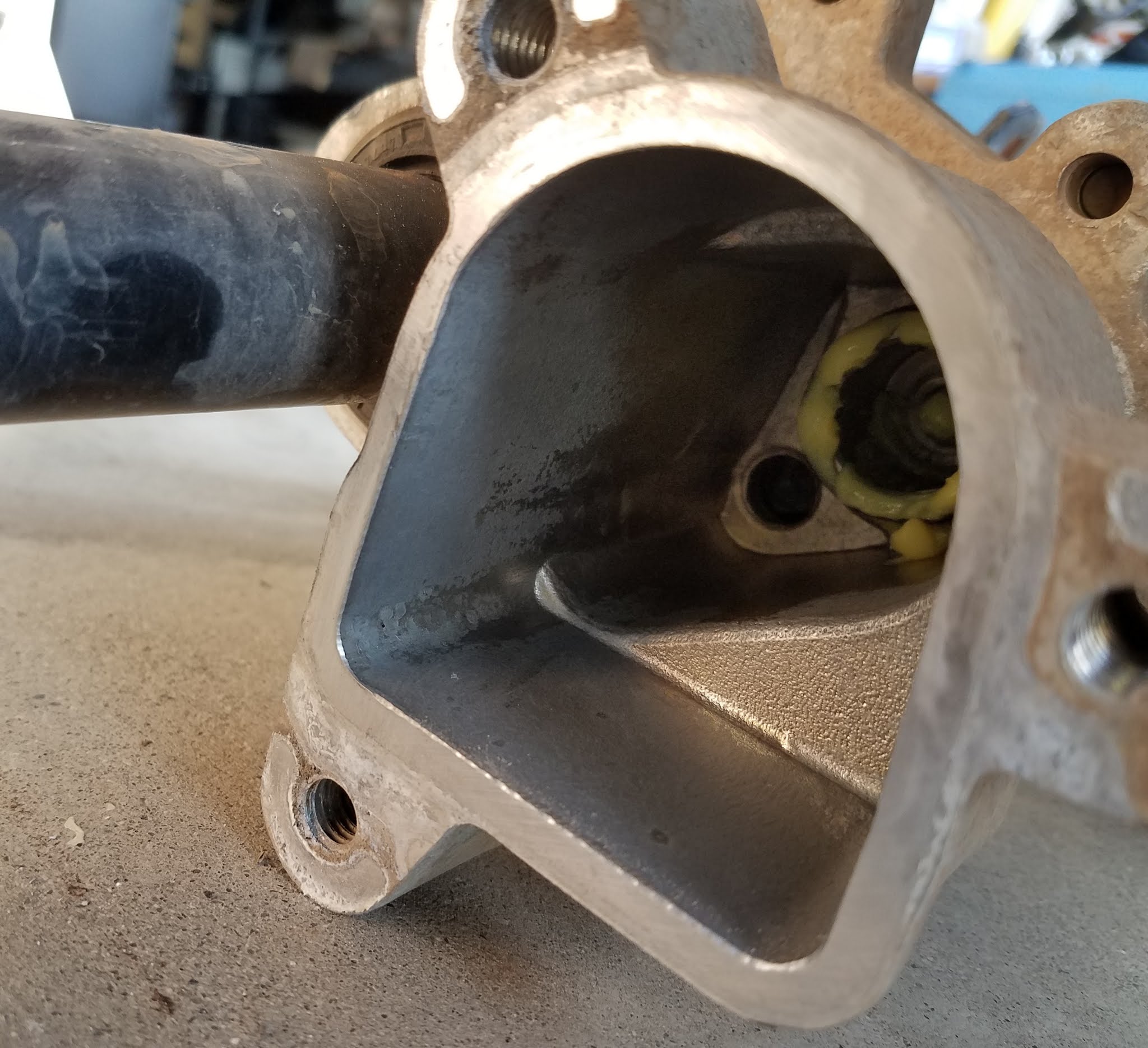
Figure 4: The fork with the outside gear-cam thingie. To disengage the sway bar, the outer gear is pushed out further than shown, disconnecting it from the end of the sway bar seen in the picture above and allowing the two halves of the rod to move independently. Click on the image for a larger version.
When one "reconnects" the sway bar for normal driving, the motor retracts the lead screw and another (weaker) spring pushes the fork that causes tension on the outside gear so that it will move back, covering both of the gears on the ends of the sway bar. Again, some vehicle movement - particularly rocking of the vehicle - is required to allow the two gears to align so that the outer gear can slip over the splines and lock them into place.
In order to detect when the sway bar shafts are coupled properly, there's a rod that touches the fork that moves the outer gear and this goes to a switch to detect the position of the fork - and in this way, it can determine if the sway bar is coupled or uncoupled. With everything disassembled, I plugged the motor unit back in and pushed the sway bar button and the lead screw dutifully moved back and forth - and pushing on the bar used to sense the position of the fork seemed to satisfy the computer and when pushed in, it happily showed that the sway bar was properly engaged.
What was wrong?
I was fortunate in that there seemed to be nothing obviously wrong mechanically or electrically (e.g. no corrosion or dirt) - so why was I having problems?
I manually moved the fork back and forth, noticing that it seemed to "stick" occasionally. Removing the fork and moving just the outer gear by itself, I could feel this sticking, indicating that it wasn't the fork that was hanging up. Using a magnifier, I looked at the teeth of the gears and noticed some small blobs in the grease - but poking them with a small screwdriver caused them to yield.
Figure 5: Embedded in the grease are blobs of pink rubber from the seal, seen in the background. Click on the image for a larger version.
Digging a few of these out, I rubbed them with a paper towel and discovered that they were of the same pink rubber that comprised the seals: Apparently, when the unit was manufactured, either the seal was pushed in too far, or there was a bit of extra "flash" on the molded portion of the seals - and as things moved back and forth, quite a few of these small pieces of rubber were liberated, finding their way into the works, jamming the mechanism.
Using tweezers, paper towels, small screwdrivers and cotton swabs, I carefully cleaned all of the gears (the two sets on the sway bar ends and the "outside" ring gear) of the rubber. A bit of inspection seemed to indicate that wherever these rubber bits had been coming from had already worn away and more were not likely to follow any time soon.
Figure 6: More pink blobs - this time on the gear on the other sway bar. Hopefully whatever "flash" from the seal had produced them has since worn down and no more will be produced! Click on the image for a larger version.
Putting an appropriate of synthetic grease to replace that removed, I reassembled the unit and put it back on the car, pushed the button. Upon reassembly, I applied a light layer of grease on all of the moving surfaces involved with the shifting fork - some of which may have been sparsely lubricated upon installation. I also put a few drops of light, synthetic (PTFE) oil on the leadscrew and the shaft that operated the sensing switch as both seemed to be totally devoid of any lubrication.
Although there was no sign of corrosion, I applied an appropriate amount of silicone dielectric grease to the electrical connector and its seal - just to be safe.
Did it work?
With the engine off, but in "4-Low", I could hear the lead screw motor move back and forth, and upon rocking the car gently I could hear the fork snap back and forth as it sought its proper position. Meanwhile, on the dashboard, the "Sway Bar" light properly indicated the state of the mechanism: Problem solved!
All of this took about two hours to complete, but now that I know my way around it, I could probably do it in about half the time.
Random comments:
I'd never really tried it before, but I was unsure if the motor would operate if the engine was not running: It does - pressing the "Sway Bar" button alternately winds the lead screw in and out - but it's not really obvious as to its position if the cam doesn't lock into place and the light turns on solid or goes out. Of course, this thing doesn't operate unless one has shifted to four wheel drive, low range.
June 2023 update:
I have had - and continue to have - NO problems at all with the sway bar mechanism. When I push the button to disconnect or - in particular, reconnect - it does so immediately- something that did not always happen prior to my working on it.