Reading view

There are new articles available, click to refresh the page.

Ham Radio Tech: RF Management–In the Field

This is the first of a two-part article about RF when you are operating “in the field,” meaning away from a fixed station.

For example, when you are operating a portable station for Parks On The Air (POTA), that’s considered “in the field” whether you are in an actual field or a parking lot or not even outside. Field Day certainly qualifies in most cases.

Because these are temporary situations, you have to apply a different set of techniques to get everything working and keep it working.

“RF Management”–What Does That Mean?

In both parts of this article, I’ll consider the RF to be from your transmitted signal. There is certainly RF floating around from other signals, and some might be very strong, but let’s deal with your transmitted signal here.

What does the “management” part mean, though?

I have been using the term to include all of the various techniques that are used to keep our RF where it belongs and out of where it doesn’t belong. That includes configuring your station so that it performs correctly when you are transmitting. So, we are going “manage” how your station performs when the strong RF is present.

As you’ll see, that covers a surprisingly wide range of concerns.

Where Is the RF? 

Better to ask, Where isn’t the RF? That is really a better question than the first part.

We tend to think of our station as “over here” and the antenna radiating RF as “over there,” so the RF just flies away in the direction of other stations. Well, not quite. You, the operator, and your station are very, very close to where that strong RF is launched, at least electrically.

Let’s ask a question: What is the wavelength of a 40 meter signal?

Not a trick question! It’s about 40 meters, which is about 132 feet. More specifically, a 7.15 MHz signal has a wavelength of about 42 meters, which is about 137 feet.

Note that only two of the HF bands contain the wavelength by which they’re known: 160 meters at 1.875 MHz and 80 meters at 3.75 MHz.

If your 40 meter antenna is closer to you than about 1/2 wavelength, or 60-something feet, you’re right in the near field of the antenna! It takes another 100 feet or more to get you out of the strong RF field.

The resulting strength of your signal is going to be STRONG!

rf grounding diagram for a ham radio station
In your station, fixed or portable, everything acts as an antenna! (Graphic from Grounding & Bonding for the Radio Amateur, 2nd Edition, courtesy of the ARRL)

As a result, RF is going to be picked up by just about every bit of conductive material within 100 feet or more of the antenna. Pro tip—you are conductive as well.

Everything in your station—everything—is going to have RF voltage and RF current on it. Unless you are operating in a metal shipping container, you might as well figure out how to deal with RF.

Let’s start with your station equipment.

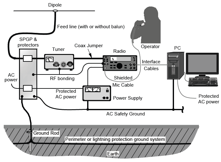
RF and the Equipment Table—Bonding

Take a look at your typical portable setup. There will be a radio, power supply, maybe an antenna tuner, a laptop or tablet for logging and digital modes, headphones or other audio gear, and a gadget or two. All of these are connected together with short antennas…er…wires and cables.

If you just throw everything on the table and hook it all up, there are lots of paths for RF to follow. Some might be low impedance so the RF current is high, and some might be high impedance so the RF voltage is high. The end of any unconnected wire or cable will be a high impedance point and that’s where you get an “RF burn”—on microphones, keys, and isolated metal boxes. You never forget an RF burn on your lips from touching a “hot” metal microphone!

These aren’t particularly hazardous, but they are obnoxious!

Even more obnoxious is equipment misbehaving when you press the key or mike switch. Maybe an automatic tuner decides to suddenly re-tune, a computer keyboard freezes up, or a radio changes a setting. This is caused by RF current getting into (or out of) something it shouldn’t. And what causes RF current to flow? RF voltage! More specifically, a difference of RF voltage between pieces of equipment.

If you can minimize the difference in voltage between pieces of equipment, you will also minimize RF current flowing between them along connecting cables.

That’s what bonding does for you.

If you look up “bonding” in an electrical dictionary, you’ll find that it is “a connection between two points to keep them at the same potential or voltage.” That’s all—no fancy implications or calculations. You just want to keep everything on the equipment table at the same voltage, and you do that by bonding them together with heavy wires or straps. The wires and straps should be short so they don’t have an appreciable impedance of their own.

In a portable setup, the easiest way to bond everything is to connect all of the equipment directly together. Have an assortment of jumper wires (#12-16 is good) or straps (flat tinned braid works well) that connect to screws on the metal enclosures. Powerpole connectors on the wires allow the equipment to be bonded however you arrange it. I recommend using green wire insulation and connector bodies, signifying a ground connection.

Another option is to put some aluminum foil under all the equipment and connect the enclosures to it with heavy test clip leads (#18 or heavier). The metal surface helps equalize voltage.

This is a great addition to any go-kit and has saved Field Day for me more than once.

The foil weighs hardly anything, so you can even use it for Summits On The Air (SOTA) stations carried in your pack. When you’re done, wad it up and recycle it. The foil surface should be big enough to cover a strip under all your equipment. I find a three-to-four-foot strip is more than adequate.

RF and the Station Wiring

What about all those cables connecting everything together? There are three basic techniques that will reduce or eliminate most RF problems:

  1. Use the shortest cables you can. One-foot USB and audio cables are available. 
  2. Coil up excess cable in a figure-8 to minimize its inductance and the RF voltage it will pick up.
  3. Use shielded cables for everything and avoid plastic, unshielded boxes for equipment enclosures.
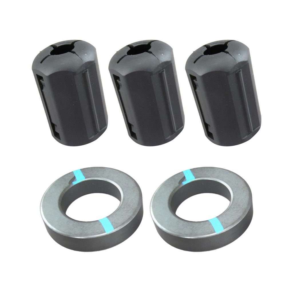
  4. Have Type/Mix 31 (preferred) or 43 ferrite clamp-on cores available.

What is a figure-8 winding? This is a handy technique for all kinds of cable, including coax feed lines, power cables, and extension cords. The basic idea is illustrated in the last half of this YouTube video on cable winding for video work. If you practice these techniques, you’ll avoid creating a spiral twist that creates kinks. For small cables, you can wind the figure-8, then fold the two halves together. Winding half the turns in opposite directions causes a magnetic field to create equal-but-opposite voltages in the coil, minimizing RF pickup.

If you use the aluminum foil approach or have a metal table, lay the cables, including the excess length all coiled up, on the foil. That minimizes the length of cable exposed to the RF fields.

If you do need the ferrite cores, place them on the affected cable as close to the equipment experiencing interference as possible. Wind several turns of the cable onto the core before snapping it shut. Be sure both surfaces of the core are flat against each other. This creates an impedance that blocks the RF current where it is getting into the equipment.

If you’re not sure what mix makes up a “mystery core,” it’s worth buying a half dozen, then labeling or color coding them as in this photo of a ferrite core kit. The toroids can be used to wind multiple turns of coax and power cords. Snap-ons can be labeled with a permanent marker or colored tape.

ferrite chokes for a wire
(Image/DX Engineering)

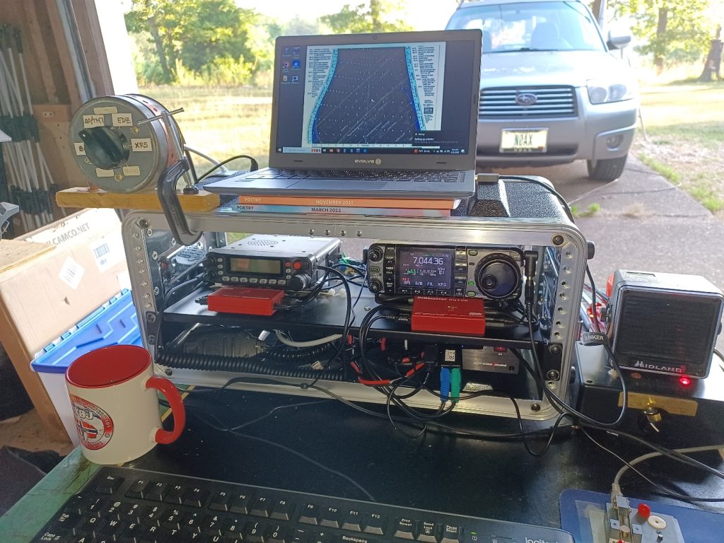
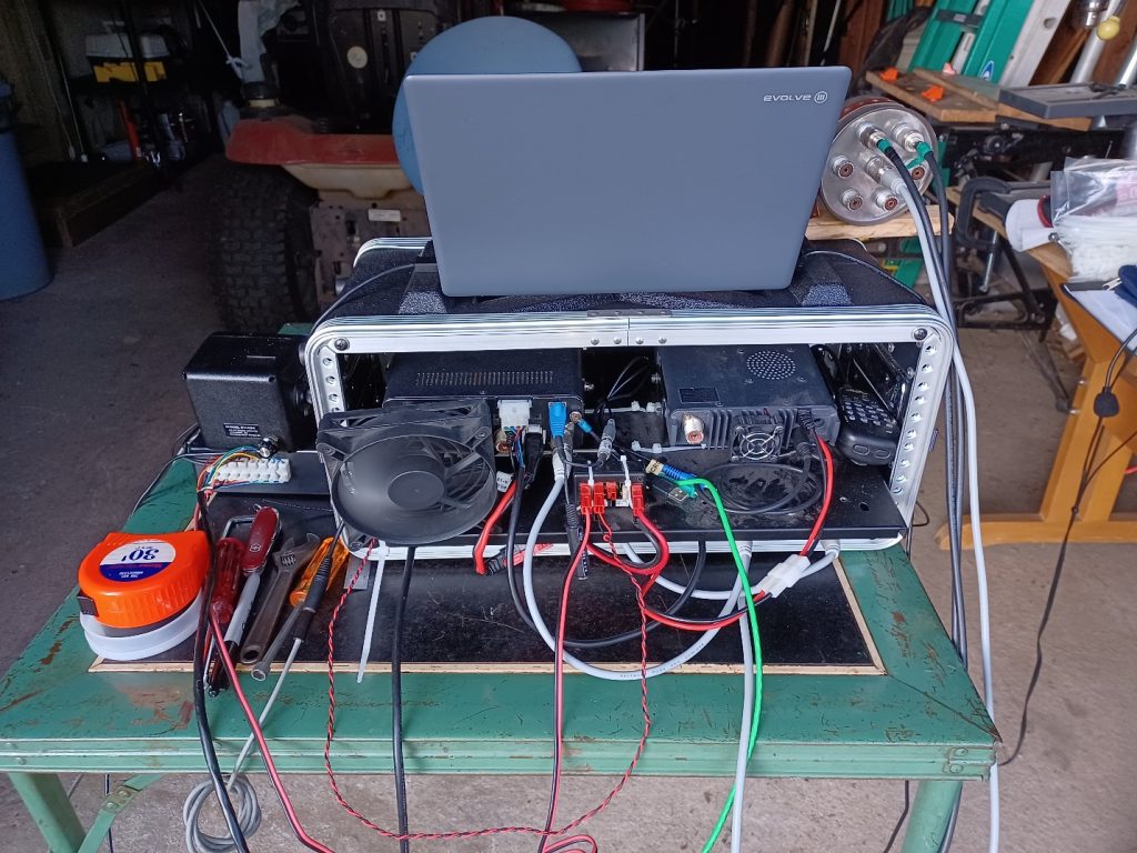
A combination approach that accomplishes bonding and keeps all of your equipment together is a portable rack. These have metal shelves and rails with an overall plastic enclosure. They’re usually available as portable audio equipment racks.

You can install all of your portable equipment more or less permanently in one of these racks. This lets you bond everything, use short cables, and debug all of the wiring so that when you take the rack of gear to the field, you know it will work with a minimum amount of setup.

True, a rack is heavier and not suitable for backpacking, but for many portable vehicle-based scenarios, it will be just fine.

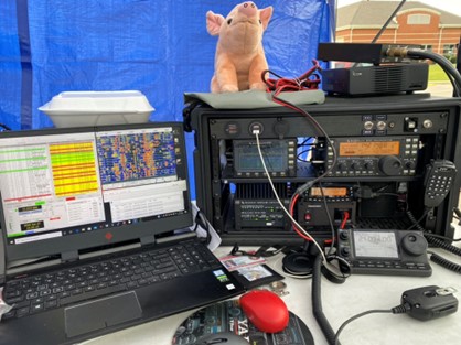
These photos are from my Field Day operation in 2023 showing an IC-7000 and an FT-7900 in a standard portable audio rack. All of the equipment is bonded to the metal rack shelf. The operating table is my great-Aunt Ruth’s!

front view of a portable ham radio station on a tabletop
(Image/Ward Silver, NØAX)
rear view of a portable ham radio station on a tabletop
(Image/Ward Silver, NØAX)

Despite your best efforts—and every field setup is different—you may find that transmitting on a particular band “lights up” the station equipment (or the operator). You might see RF interference to equipment, or a “hot spot” may cause a tingle (or more!) on some frequencies.

In this case, use a 1/4-wavelength piece of wire (calculate as 470/f in MHz–length is not critical) attached to the affected equipment on one end with an alligator clip and left open on the other. Insulate the open end.

This detuning wire will create a low-impedance point, lowering RF voltage where the wire is attached. The open end may have high voltages on it, so insulate it and don’t put it where you might touch it or step on it with bare feet! (Don’t ask me how I learned this…) Have one detuning wire for each band you plan on using.

RF on the Antenna System

Other than on the antennas themselves, as discussed earlier, RF is going to be picked up by every conductor in your station, including by the antenna feed lines as common-mode current. This is a particular challenge in mobile operation since the vehicle body is part of the antenna. The RF picked up by the feed line will flow into your station and cause problems unless you take steps to block it:

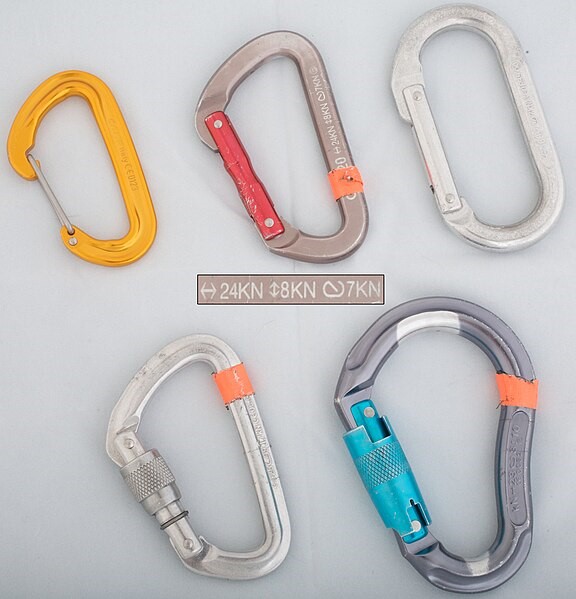
  1. Use a common-mode choke (ferrite or wound-coax) where the feed line attaches to station equipment.
  2. Add one or more chokes along the feed line between the station and antenna. If you are using an end-fed half-wave (EFHW) antenna, a choke at the impedance transformer may affect the antenna’s SWR. Check the antenna manual for guidance.
  3. If you are using a vertical antenna, such as a whip with a base-loading coil close to the ground, place some chicken wire or hardware cloth under the antenna to act as a ground plane. Route the feed line underneath it to maximize the shielding effect.
  4. If your antenna is mounted on a vehicle, bond the antenna mount to the body with a heavy wire as close to the mount as possible. This helps keep the feed line from becoming part of the antenna.
  5. In a vehicle, operate with the doors closed to keep RF on the outer surfaces. A ferrite choke where a feed line enters the vehicle is also helpful.

Finally, what about a ground connection to the Earth itself?

Generally, you don’t need one! Most generators do not require a ground rod or connection—check the manual.

A vertical antenna will require radials or a ground screen as in item three above but does not need a direct connection to the soil. Horizontally polarized antennas like dipoles, most EFHWs, and double-whips will be de-tuned by a ground connection. In many public places, it is not allowed to drive stakes or rods into the ground.

What about lightning protection?

In a portable or mobile setup, the best advice during storms is to lower the antennas to the ground, disconnect the feed line and secure it at least six feet from the station. There is little you can do to protect your equipment from a lightning strike in the field. Take shelter yourself! If you’re in a vehicle and lightning is striking nearby, close the doors and try not to touch any metal until the storm passes.

***

This article touched on some of the important aspects of dealing with the strong RF you’ll encounter when operating a portable station. In the next article, I’ll discuss some concerns for RF safety in these setups, an often-overlooked aspect of setting up away from home.

The post Ham Radio Tech: RF Management–In the Field appeared first on OnAllBands.

How To Strip (Wires and Cables)

Let’s start with a story about how NOT to strip wires. Back in the day, I worked with a fellow who had the unique talent of stripping wires with his teeth!

Well, just two of his teeth, actually.

It seems that at some point in his youth, he chipped the adjacent corners of his two front teeth just a little bit. The size of that little gap was just right for hookup wire, telephone wire, and all sorts of other wires. He would put the wire between his teeth, bite down just a little, and pull. Voila! Wire stripped and insulation spit out.

DON’T TRY THIS AT HOME!

Lucky for us, there are many great and inexpensive tools for getting insulation off of wires. You might only need to do that occasionally or you might need to strip dozens of wire ends. Whatever your need, there is a tool for you.

Let’s start with the most common and inexpensive manual stripper.

Basic Wire Strippers

My first order of business is to warn you about the too-cheap, no-name combo tools. While it might be nice to have one of those in the glove compartment for emergencies, they really aren’t quality workbench and toolbox tools. Good tools will last and last while doing the job right, so spend the extra few bucks on a “real” wire stripper from a solid tool company. If you need to spend a few bucks to qualify for free shipping, you could do a lot worse than to buy a good spare stripper.

Below is the Klein 1010, a basic wire stripper from Klein Tools, a well-known and trusted name in the electrical industry. As you can see, it not only strips and cuts wires from 10-22 AWG but crimps terminals, cuts small screws, bends wire, and has small plier jaws.

All of these functions are demonstrated in this handy video, “8 Wire Stripper Features Everyone Should Know.”

This is a low-maintenance tool. Keep it clean and free of rust and it will be your toolbox buddy forever.

close up of a set of wire stripper heads
(Image/DX Engineering)

Once I discovered it, I’ve used the small-screw cutter many times, making a short screw that was just right for the job. The important thing is to insert the screw so that after it’s been cut, you use the threaded part of the cutter to clean and re-align any distorted threads as you removed the screw. And sometimes, the little studs that are left can be used to join nuts or spacers.

You can tell I never throw anything away!

If you do a lot of home AC wiring, you can also find heavier strippers designed for the Romex-style cable and wire sizes you’ll encounter in those jobs. These will do a better job than the small strippers for electronic and radio work. They are also a little easier on your hands for the harder squeezing and pulling necessary for that type of work.

The pocket-friendly Squirt ES4 is a nice variation in the Leatherman line of multi-tools. Widely available used and occasionally new or in similar models, it includes a dandy little combination of wire stripper/cutter/needle-nosed pliers.

Folded up, the tool is less than two inches long. You’ll forget you’re carrying it, which is a bad thing if you try to take it through airport security! I’ve had to give up a couple of these that way, which is probably why they’re available used! Larger Leatherman multi-tools are also available with wire strippers.

folding multi tool pocket knife
(Image/DX Engineering)

Using manual strippers is pretty straightforward: insert the wire into the appropriate hole, squeeze, and pull. But there are a few fine points:

  • Be sure to use the right size hole, otherwise you’ll nick solid wire (leading it to break when bent) or cut off strands of stranded wire.
  • Using a too-large hole means you’ll get a ragged edge on the insulation and often pull the wire out of a multi-conductor cable.
  • Don’t rock the stripper back and forth because that will nick the wire. If you have to do this to get the insulation off, either you’ve used the wrong hole or the jaws are dull and the tool should be replaced.
  • Pull the wire straight through the stripper and don’t bend it, causing nicks and cutting strands.
  • If you find the stripping force pulling one wire out of a multi-conductor cable, use needle-nosed pliers to hold the wire while it’s being stripped.

Using a diagonal wire cutter as a stripper is a skill many of us old-timers have developed. Like my friend with the chipped teeth, there is a knack to doing it without damaging the wire. A gentle squeeze will put a nick in the insulation which will then break and slide off the wire. This will only work reliably on insulation that breaks cleanly and won’t leave a clean edge on the insulation. 

Automatic Strippers

Sometimes you’ll find yourself faced with having to strip many wires for a big wiring job or preparing multi-conductor cable for a rotator or control circuit.  If you are installing crimp terminals or connector pins, you need to strip all of the wires consistently and with the right length of exposed wire. This is where a self-adjusting wire stripper comes in very handy.

Properly set, these strippers will make a consistent, clean strip over and over. That results in higher quality work with better reliability.

Another item in the Klein Tools catalog, the Klein 11061 is a typical example of these tools. They don’t have all of the accessory features of the 1010 but make short and consistent (there’s that word again) work of stripping a lot of wires. After you insert the wire between the jaws, squeeze the handles—the jaws clamp the wire, and the blades come together to cut and pull off the insulation.

Here’s a video of how to use it and how they work

Klein Wire Stripping Tool
(Image/DX Engineering)

The Performance Tool W200 is a variation of the automatic strippers. It has jaws to hold the wire and a pair of cutting blades that come together and pull off the insulation. The sequence is completely automatic and the design of these tools to make this sequence happen is pretty nifty.

Wire stripping tool with red handles
(Image/DX Engineering)

Pistol-grip adjustable automatic strippers are also available, such as the Tool Aid 19100. The wire is inserted in the end of the jaws until it contacts the adjustable stop. Squeeze the jaws and the tool does the rest. This tool is intended for smaller gauge wire from 12 to 22 AWG.

I’ve used all of the different types of strippers and each has their appropriate role. I carry a manual and an automatic stripper in my tool kit. These are also fairly inexpensive and worth adding to your tool roster. You might also enjoy Adam Savage demonstrating how these work in this entertaining video.

Stripping Enameled Wire

So far, we’ve focused on wire with plastic insulation, and that is most of the jobs you’ll encounter. However, if you wind toroids or impedance transformers or baluns, it’s common to use enameled wire which is harder to strip. You want to avoid nicking the wire with a cutter or knife—it will break from mechanical or thermal flexing—so a different technique is required.

A convenient method for occasional use is to use sandpaper or emery boards. A small strip of sandpaper held between your fingers to squeeze the wire is an easy skill to learn. Squeeze the wire, rotate it, and pull it in and out of the sandpaper. This scrapes off the enamel without damaging the wire underneath.

This video shows how to do it properly.

If you have a big project with a lot of inductors or transformers, you can save yourself a lot of work (and sore hands) by using a power tool to scrape off the enamel. The Abisofix tool shown in the photo and this video will do the job on a wide range of wire sizes from 12 to 24 AWG. For very fine wires, the manual method is best for the home builder.

power wire stripping tool
(Image/DX Engineering)

Removing Heavy Insulation

A situation you’ll encounter frequently is removing the outer insulation from multi-conductor cables like rotator control or networking cable. If you don’t have a special cable stripper, you’ll have to use a knife or razor blade to remove the insulation. Be sure to use a SHARP, new blade for a utility or craft knife. A dull blade will make this job hard to do well.

  1. Score the insulation—cut the insulation but not all the way through. You can hold the cable in one hand and cut with the other, but an easier and more controlled way is to place the cable on a work surface and roll it under the blade.
  2. Do not cut into any of the inner conductors. It’s best to cut too shallowly at first, then go deeper as needed.
  3. Bend the insulation back and forth so that it breaks along the score. You may need to touch up the scoring in spots.
  4. Twist the insulation off in the same direction that the individual strands twist.

If you are working with coaxial cable, use a stripping tool for coax if possible. Those tools are well-covered in other On All Bands articles and videos.

However, sometimes you have to strip coax manually. First, when removing the outer insulation, be extra careful not to cut through the fine strands of shield braid. Take your time and work through the outer insulation. Use your sharpest wire cutters when removing the braid. Then repeat the score-and-bend technique to loosen the center insulation. 

It’s often hard to pull off coax’s solid center insulation without pulling it partially out of the braid. You can use manual wire strippers to hold the remaining insulation while pulling off the unwanted part. Carefully close the strippers on the center conductor using a stripper hole one or two wire sizes larger than the conductor so it doesn’t nick the coax conductor. Then slowly pull off the center insulation, remembering to twist the insulation in the same direction as the strands of wire.

Use the Right Tool

Just to repeat the message, use the right tool for the job and learn how to use it properly. So many problems in the ham station trace back to connectors and wires breaking or pulling loose. By doing it right the first time, you can save yourself a lot of headaches and keep ham radio fun. No matter what the type of wire or cable, there has probably been a special tool designed for it.

Many are quite inexpensive—don’t you have a birthday coming up?

The post How To Strip (Wires and Cables) appeared first on OnAllBands.

Ham Radio Tech: Knots & Slings

Antenna and tower work are never far from our minds as hams. Most amateur loads are considered light by professional installers, but they can be heavy enough to cause injuries if mishandled or poorly secured. This article is an overview of ropes, knots, and slings which are used by hams. Since most of us are not professionals, it’s always a good idea to review and brush up our skills before “game day.”

Two complementary resources are sold by DX Engineering: “Up the Tower” by K7LXC and the ARRL’s “Antenna Towers for Radio Amateurs” by K4ZA. The first features a lot of information on rigging, including ropes, slings, and tools. The second discusses how to properly build a tower system. You should review both of these references, which go into far more detail than this article.

up the tower ham radio book cover
(Image/DX Engineering)

OnAllBands also features an excellent five-part series, “Amateur Radio Tower Safety,” featuring W3YQ. Please be safe when climbing and working aloft. Take advantage of the excellent training material that is available to you!

Lifting & Lowering

Except for the lightest loads, always use a suitably rated pulley or block when raising and lowering items. Avoid the small hardware store pulleys that are not rated for heavy loads. Light-duty hardware is often stamped or labeled as unsuitable for climbing and lifting—heed that warning!

The snatch block is the most useful since the rope does not have to be threaded through the pulley—one side opens so the pulley can be placed directly on the rope, even when it is tied off at both ends. This is called “snatching the rope.” 

bluewater pulley block
(Image/Ward Silver)

The snatch block pulley shown in the photo is rated at a working load of 24 kN (kilo-Newtons), which is about 5,400 lbs. Marine and construction pulleys are also available, although they weigh more. Get pulleys with sheaves that fit your rope so it can’t slip and jam between the sheave and body of the pulley. Watch for sales and have a few pulleys in your tool kit.

Rope

For basic tower and antenna work, Dacron and nylon ropes are preferred. A kernmantle rope has a braided sleeve that protects the rope’s core. For tower work, use a 3/8 or 1/2 inch rope because they can handle heavy loads and are easier on your hands than thinner ropes. Inexpensive polypropylene rope is useful for light lifts—such as the tool bucket or a rotator. Wear sturdy gloves when working with a rope under load so that if the load slips, your hands won’t be burned from friction.

Remember that to lift something to a certain height, you’ll need at least twice that length of rope, and another 50% of length is recommended. Try to have at least two load-rated ropes available.

There are two strength ratings for rope: breaking strength and working load limit. The breaking strength is usually three times the working load rating. Try not to use ropes near or at their load limit.

Using ropes as temporary guys should be done with caution and rarely, if ever, as permanent guys. Stretching varieties, such as nylon, should never be used as a guy line. Use a low-stretch rope material, such as Dacron, and be sure it is well within its load limit.

Knots

There are many, many types of knots and you should find a how-to book or website that shows how to tie the basic knots. If you’re a beginner, some essential knots are demonstrated on the Columbus McKinnon YouTube channel. This site is about entertainment rigging, which is a lot like basic ham radio rigging! For more advanced knots, resources such as animatedknots.com show you exactly how to tie knots (it also includes a beginner’s section).

The most common types of knots used in antenna and tower work are hitches that pull on or lift tubing and tower sections. The below photo shows two half hitches:

two half hitches knot tied around table leg
(Image/Public Domain)

Another common knot is the bowline, which is very useful because it doesn’t slip and can be untied relatively easily, even after being used with a heavy load. I use it for tying ropes to antenna insulators because I can untie a bowline even after the rope has been out in the weather for months.

drawing of a bowline rope knot
(Image/Public Domain)

There are lots and lots of instructions for how to tie a bowline. Many of us of a certain age learned the “make a hole next to the tree, the rabbit comes up through the hole, goes around the tree, and back in the hole” method. This video, however, is probably easier to learn! You might also try to learn the one-handed bowline so you can tie a secure knot with one hand while the other is holding a load—a not unusual situation aloft.

Carabiners

To attach a rope to a structure, a climbing harness, or other rope, carabiners are often used. An assortment is shown in the photo below.

Clockwise from top left are a D shape wire gate, straight gate, oval shape straight gate, auto lock, and twist lock. The straight gate versions are the most common in antenna and tower work.

collection of carabiners
(Image/Assorted Biners by Zakabog | CC BY-SA 3.0)

Note the load ratings in the middle. The highest rating of 24 kN is the breaking load with the gate closed. The working load is one-third of the breaking rating. The smallest value is the maximum load with the gate open. Lightweight clips that look and act like carabiners are often sold as keychains or hangars but should never be used for lifting loads! They are stamped with warnings showing they are not to be used for load lifting.

Slings

Rather than tie a rope directly to the workpiece, a synthetic web sling is much more convenient to use. Visit Hoistwire.com for images of various web slings, including common types such as the endless sling and those with eyes at the end. There are also rope, wire rope, and chain slings, but those are not often used for ham radio jobs.

For a complete table of single-ply web sling ratings, see Table 22 “Rated Load for Two-Ply, Class 5 Synthetic Webbing Slings Expressed in Pounds” here: OSHA.gov.

The three most basic uses of slings are straight, choker, and basket as displayed at PracticalMaintenance.net, which shows many ways of using slings and how to determine the load rating of each method.

An assortment of web slings comes in handy for antenna and tower work. Most lifts will use slings from 18 to 36 inches long. One inch wide slings will handle nearly all antennas. A pair of 36 inch slings configured as a bridal hitch make a stable and strong way to lift a Yagi boom. I recommend having at least two slings of several lengths.

If you plan on lifting a tower with a boom truck or crane, use heavier slings that are two inch wide or more. Consult with the crane operator first.

Storage and Maintenance

Finally, you really need to take good care of anything you depend on for safely working on antennas and towers! After the job is done, lower your ropes into a plastic milk crate or bucket. The rope won’t tangle and will then pull out easily without kinking or knotting. Larger and longer ropes can be wound on a portable hose reel.

As you store ropes and slings, inspect them carefully for chafing or cutting that may have occurred in use. Look for carabiner gates that are twisted or won’t latch securely. Damage beyond superficial wear is enough to warrant replacement.

If your crew is going to be bringing some of their own gear, label your stuff! A permanent marker will help you keep your gear separate from that of others. Colored tape will also make it easy to tell everyone’s stuff apart.

Ropes and slings need to be kept clean, dry, and away from where rodents and insects can get at them. Avoid kinks and sets by making sure there are no tight knots or bends in storage. Keep them away from oil and grease that might degrade the fibers.

Take care of your gear and it will take care of you!

Editor’s Note: DX Engineering carries a variety of rope in a range of diameters and break strengths, along with rope hardware kits to work with different sizes of Mastrant rope.

The post Ham Radio Tech: Knots & Slings appeared first on OnAllBands.

Effective Field Day Operating

Operating at Field Day is lot different than operating a home station—and that’s more than half the fun. It’s also one of the main reasons Field Day exists, so that you get some practice under more stressful conditions than at home. The first Field Day in 1930 was held specifically to test amateurs’ ability to communicate in emergencies and after disasters. After all, it became part of the amateur service’s Basis and Purpose in Part 97.1(a)—our very first rule!

You want to be effective under those conditions, of course. Because the circumstances are so different than operating from home, you’ll have to learn some new techniques and approaches to operating. Having participated in more than fifty Field Days, here are some suggestions to make you a more effective communicator. I learn something new every time, and you will too.

Field Day vs. Other Contests

Is Field Day a contest? It all depends on how your group approaches it. It’s not part of the regular ARRL Contest Program, but if you are trying to get a higher score than that club across town, it sure feels competitive! The scoring rules provide a great yardstick for evaluating your performance, so if you want to treat it like a contest, go for it.

The first thing you must be aware of is the big difference from a regular contest for which fixed stations have been carefully constructed and optimized. I’ve operated at some very capable Field Day stations, but most aren’t as big and powerful as at home. The usual Field Day situation on HF is to run 100W or less using antennas that are usually just a fraction of a wavelength above ground, particularly on 40, 80, and 160 meters. On VHF/UHF, it’s a lot easier to install antennas at a wavelength or more above the ground, but the antennas are often smaller in order to be portable.

TIP: On CW, SSB, and digital modes like FT4 and FT8, most VHF/UHF signals will be horizontally polarized. Use vertical polarization for FM simplex.

Propagation—Get Ready

Knowing what to expect from propagation will also pay big benefits on Field Day since you won’t be able to rely on a big station to power your way through. Summertime propagation is often quite different from even late spring. 

TIP: Listen for a few days before Field Day to get an idea of when the bands are open. Use a propagation prediction service or prepared tables to plan for the best times and bands. Check out logs from previous years to see when stations were making contacts.

Use the different types of propagation to your advantage and be prepared for what you’re likely to encounter. 

TIP: On VHF, remember that you’ll be operating during prime sporadic-Eseason, so be prepared to take advantage of those openings on 6 and 2 meters. On HF, things may get started slowly because of the high absorption during summer around local noon. Practice NVIS (Near Vertical Incidence Skywave) operating during these hours. The bands will probably pick up in the afternoon. In the evening, 40 meters is often open coast-to-coast. Later on, 80 and 75 meters can provide lots of contacts.

Learning to Use Unfamiliar Equipment

Using low power and smaller, lower antennas relies more on the operator to get through and make contacts on the HF bands. You may be operating your own equipment, but frequently it’s someone else’s radio or spare radio dedicated to portable operating. 

TIP: Before beginning to operate, spend a few minutes learning the controls and configuration of the new radio and any accessories. Receiver controls like filter bandwidth, RF gain, attenuation/preamp, and noise blanker/reduction are very important. Don’t be afraid to ask how to use the radio correctly!

If you are the equipment owner, be available to help other operators learn to use it. After all, you want to avoid damage to the equipment or having to figure out how another operator may have scrambled the various settings and selections! 

TIP: Bring a copy of the operating manual or download the PDF version to your phone. Use sticky notes to show where the most important sections are. If you have preferred settings, label front-panel controls with colored tape and make a list of any menu items that are likely to need adjustment.

Avoid creating interference to your group’s stations and to other Field Day stations. Before the contest, check for clicks, splatter, and over-driving audio inputs for digital modes. A clean signal is a more effective signal. Even if the radio meets FCC rules, several stations at the same location really put a premium on signal cleanliness, particularly wide-band noise.

TIP: Bring band-pass filters, either LC circuits or transmission line “stubs,” to reduce out-of-band harmonics and noise from your radio.

You may also enjoy this article: Noise Management on Field Day

Know How to Log Contacts

Even more confusing than new equipment, learning how to use someone else’s logging computer and software can be a challenge. Make sure the entire group knows what software will be in use. If there is a free or evaluation version, encourage them to download and use it for practice. Cheat sheets of what keys perform what function are very helpful! Make sure you have the latest version that includes the latest ARRL/RAC sections.

TIP: Just like unfamiliar equipment, watch the previous operator use the software before you start operating. If the software has the ability to record the operator calls, be sure you “log in” before starting to operate.

The Field Day exchange is very simple: Category and ARRL/RAC Section as defined by the Field Day rules. One of the most common mistakes, though, is entering (or attempting to enter) an incorrect section abbreviation. 

TIP: New operators should get some tutoring to be sure they know what they are supposed to enter, particularly the many state/province abbreviations that begin with M: MA, MB, MD, ME, MI, MN, MO, MS, MT. Ontario has four sections: GH, ONE, ONS, and ONN. California’s Los Angeles section is abbreviated LAX, while Louisiana is just LA. A cheat sheet is pretty handy!

Operator Comfort

Operating outside can be surprisingly challenging. The weather can be too hot in the day and too cold at night, to say nothing of rain, bugs, wind, and so on. Be prepared! Check out your kit in advance and don’t wait until Game Day to find out your tent is missing the rain fly.

TIP: Dress in layers with all the necessary sunscreen, bug repellent, sunglasses, etc. in your Field Day kit.

Just like at a big contest station, remember that the operator will be sitting at the radio for hours. Tables tend to be camping or picnic tables, which are not the optimum height for radio operating. Make sure the tables and chairs will keep the operator relatively comfortable.

TIP: Avoid the low-slung fabric fold-up chairs in the operating tent. They are great for listening to a concert but TERRIBLE for operating at a table. Bring metal or wood folding chairs with a solid seat. A seat pad is also recommended. Nothing’s worse than a sore back or butt at Field Day!

Another commonly overlooked issue is noise. Not electrical noise but acoustic noise! Noise from wind and portable generators, conversations from visitors and non-operating operators, and audio from the other stations can all be very distracting. Pay attention to noise when locating the stations. Remind everyone to be quiet around the operators.

TIP: Use a headset with a boom mic since a small radio speaker may not have enough audio oomph outside. So that visitors can hear what you’re doing, a communication speaker that can switch between speaker-only, headphones-only, and speaker-and-headphones is quite handy. A simple splitter to share the audio can also work.

Operating Style and Courtesy

The question of “courteous vs. efficient” seems to come up every year. Speaking as a longtime ham, on the radio, being efficient is what makes an operator courteous. That is what good radio practice is all about—getting the message through with a minimum of extra transmissions. Field Day has always been a training exercise, so practice your best operating techniques. Minimize unnecessary words and phrases as if you were in a real emergency. Especially if signals are weak or in heavy QRM, extra information only makes it harder to understand, no matter what mode.

TIP: If you don’t need to say it, don’t send it.

***

Here’s a brisk, efficient Field Day QSO:

Me: CQ Field Day, CQ Field Day November-Zero-Alpha-Xray N-Zero-A-X

TIP: A snappy 2-by-2 CQ, nothing but the CQ and my call sign, no “from” or ending “Field Day” or “over.”

You: Whiskey-One-Alpha-Whiskey

TIP: Just one complete call, no repeats, no “over,” don’t start with my call–I already know it! Repeat your call if I don’t respond in a second or two.

Me: Whiskey-One-Alpha-Whiskey, 1 Alpha, Missouri

TIP: Give the contacted station and the exchange, no “you are,” no “thank you,” no “over,” no “please copy.”

You: N-Zero-A-X, 2-Delta, Connecticut

TIP: Give my call if there is any question about who you’re responding to. Otherwise it’s not necessary, and don’t repeat my exchange.

Me: Thanks, N-Zero-A-X

TIP: Acknowledge and give my call for the next station to respond.

***

That’s what courtesy looks like on the air. We’re not holding the door for each other at the store or passing the salt! If you need a repeat, just ask: “What’s your section?” or “What’s your category?” If you need a repeat of a call sign, use standard phonetics. (Save the funny ones like “Fuzzy Rabbit” for late night 75 meter fun.) It looks much the same on CW. One nice thing about FT8 is that it is definitely efficient!

TIP: New operators often get flustered or have a bit of mic fright, so help them out with a script showing exactly what to say and when to say it. Sit with them and guide them along, pointing to each step, reminding them to breathe.

That’s a Wrap!

Basically, it boils down to understanding what you’ll be doing, being prepared, and honing your technique to get the job done with a minimum of fuss and bother. That’s what the good operators do! I hope you’ll find yourself enjoying the benefits of good operating during Field Day, too.

field day ham radio station
(Image/Elizabeth Klinc, KE8FMJ)

The post Effective Field Day Operating appeared first on OnAllBands.

Noise Management on Field Day

Here comes Field Day and all of your careful equipment connections and filtering go out the window as the station is disassembled and hauled off to the operating site. Be aware that operating in a multi-station environment, like the popular 2A category, requires that all of the transmitters be “clean.” That is, transmit a minimum of spurious emissions like harmonics, intermodulation products, and the bugaboo of wideband noise.

One “bad apple” can really be aggravating, so here are a few techniques you can use to keep the peace.

If you want to know more about interstation interference, one of the best references is “Managing Interstation Interference” by W2VJN. It’s available as a PDF download here from Vibroplex. It covers filters, stubs, and other techniques.

managing interstation interference book cover page
(Image/Vibroplex)

Lightning Protection

Before we discuss noise, let’s start with the understanding that lightning protection is pretty much impossible for a portable station. Your ground system will be temporary and very lightweight. A ground rod or two just won’t do the job either. What to do? When lightning is in the area—say, within five miles—that’s the time to lower your antennas, disconnect the feed lines and power cords, and get away from the equipment. A lightning detector, such those available from Weather Shack or other vendors, is a good idea. Lightning monitoring apps such as www.blitzortung.org (below) are available for smartphones, tablets, and PCs.

screengrab of a map displayed on a computer
(Image/Ward Silver, NØAX)

When you disconnect feed lines, move them at least six feet away from any equipment and preferably a lot farther. Wait until the lightning has moved on before reconnecting your station.

Wideband Noise

The most common noise problem encountered on Field Day is wideband noise from a transmitter. Depending on the transmitter’s structure, the noise might be limited to the frequencies near the transmitted signal, just to the band of the signal, or across several bands. The cause is almost always noise on the oscillator(s) in the transmitter.

Noise close to a transmitted signal covers up weak signals on adjacent frequencies. As the noisy transmitter tunes closer to your listening frequency, you’ll hear the noise floor increase whenever the transmitter is keyed, independent of output power. Similarly, noise will also be present on harmonics of the transmitted signal.

Wideband noise that occupies an entire band or several bands is the biggest problem for multi-station Field Day setups.

How can you tell if your transmitter is generating this type of noise? Don’t worry, operators at the other stations will tell you! Right away! Because all of the stations are so close together, the transmitted noise may make it impossible to operate.

Field Day managers should make sure that any on-site transmitter is well-behaved. Conduct a test of your radio before Field Day. Get on the air with a ham close by or have a ham with a portable receiver listen on all of the bands from several hundred feet away. If they can hear noise when you close the PTT switch, your radio has a problem.

This type of noise must be filtered at the transmitter. Once radiated, it cannot be filtered out at the receiver because it is the same as any other “in-band” signal.

Band-pass filters, such as the LP-BPF-20 filter from VA6AM Engineering below, are good practice for all stations but an absolute necessity for transmitters that generate wideband noise. A set of band-pass filters for the HF bands is a good club purchase! QRP filter kits are also available, and there are a number of schematics available online if you want to build some from scratch.

VA6AM Band Pass Filter
(Image/DX Engineering)

Even with a filter, other stations on the same band, such as a 75 meter phone and 80 meter CW or FT8 station, will experience interference from the noisy transmitter.

The best solution to wideband noise is to not generate it in the first place. Test all transmitters before Field Day and leave the noisemakers at home. Be aware that you may be completely unaware that you have a noisy transmitter. After all, you probably aren’t receiving while you’re transmitting!

Harmonics & Intermodulation (IMD)

Every transmitter generates some harmonics. They are mostly quite weak but when you are operating more than one station in close proximity, they are strong and can cause a lot of problems. Like wideband noise, harmonics must be filtered out at the transmitter. A band-pass filter will work, or transmission line stubs can knock down harmonics. 

Even with filtering, you probably won’t be able to completely suppress harmonics. It’s a good idea to agree ahead of time on a plan to adjust operating frequencies to avoid interfering with another local station. For example, if the 20 meter station is going to operate on 14220 kHz, the 10 meter station needs to avoid 28440 kHz and nearby frequencies. Coordinate frequencies—it’s better than arguing about who’s interfering with who!

Another source of QRM is intermodulation in the transmitter or amplifier. Often a problem on phone, the different speech components mix together in the RF power devices and generate many signals outside the desired bandwidth of the output signal. This generates “splatter” and “buckshot” on nearby frequencies. 

You can reduce these unwanted signals by careful adjustment of your microphone gain and any speech processing. Before Field Day, have a nearby ham listen to your signal on a quiet band as you adjust the transmitter for the cleanest, full-power output. Take note of the settings so you don’t have to repeat the exercise on Field Day.

Key-clicks and audio IMD on digital signals are also sources of in-band interference to adjacent signals. Solid-state amplifiers are particularly susceptible to overdrive above about half their rated power output. Be a good neighbor and make sure you have signal rise-time and amplitude settings right for the best-sounding signal on adjacent channels. Run amplifiers at reduced output power to avoid generating “spurs” as well.

The ARRL is addressing these problems through the Clean Signal Initiative. As this program progresses, look for more information about how to ensure your transmitter is properly adjusted. In addition, there will be methods for comparing and evaluating signals.

Passive Harmonic Generators

Be aware that strong RF picked up on feed lines and control cables can be conducted into equipment by shields or unshielded conductors. Once inside the equipment, if the RF encounters any diodes or rectifiers (or LED indicators!) it will be partially rectified and many harmonics generated. Those harmonics go right back out by the same path and are radiated as interfering signals. 

These can be hard to troubleshoot and resolve during the short Field Day period. It may be best to simply take the minimum amount of equipment you need. Ferrite snap-on cores can be effective if you can determine which cables and equipment are causing the problem. Type 31 material is the best for HF use.

Receiver Overload

What sounds like wideband interference can often be caused by receiver overload from the strong signals of nearby transmitters. Turn off Noise Blankers, which respond to strong signals by trying to turn off the receiver during what they think is a noise pulse. This can result in what sounds like a transmitted signal “clobbering the whole band.” Turning on a preamp can result in the same problem.

Overload generally disappears as RF Gain is reduced below a threshold. You can give your receiver a little breathing room by switching in some attenuation. You’ll still be able to hear the other signals and the band may sound a lot cleaner. Only use the minimum amount of gain needed. Band-pass filters can also be used if an out-of-band signal is causing the overload.

Bonding to Prevent RF Problems

Within the station, you can help reduce harmonics and spurs by making sure all of the equipment is well-bonded together. This is particularly important if you are running an amplifier. RFI from a transmitted signal is generally caused by significant voltage between pieces of equipment. This is often a result of having antennas very close to the station, as is typical of Field Day setups. RF “hot spots” at high-voltage points are created by the same RF current.

You can address these problems with bonding—connecting equipment together to minimize voltage differences. This topic is covered in more detail by my 2022 OnAllBands article, “Grounding and Bonding for Portable Amateur Radio Stations.”

You may be surprised to find that a simple sheet of aluminum foil and some clip leads can solve a lot of RF problems!

The post Noise Management on Field Day appeared first on OnAllBands.

❌