Reading view

There are new articles available, click to refresh the page.

Ham Radio Tech: Choosing a Portable Vertical Antenna that Matches Your Needs

Whether you’re a seasoned ham or buying your first antenna, choosing the right one is more about how you operate as an individual and less about the antenna’s capabilities. In previous OnAllBands articles, I’ve explored field antennas and the decision-making process behind choosing the right one. I believe that a practical understanding of your operating style is key to making the best choice.

This article is about vertical antennas—specifically, those designed to be portable and stealthy. These antennas are ideal for field operations like POTA, SOTA, or IOTA, and for those living under HOA restrictions that prohibit permanent antennas.

portable ham antenna set up on mountainside
(Image/Thomas Witherspoon, K4SWL)

There are hundreds of vertical antennas on the market, and it’s beyond the scope of this post to cover them all. Instead, I’ll focus on three models I’ve personally used, each representing different concepts and reasons why you might choose one over another.

All of these antennas are multi-band, and while some can be installed permanently with proper sealing, they are primarily designed with portability and ease of setup in mind.

Before diving into the specifics, consider these questions as you search for your next antenna:

  1. What modes and power levels do you intend to operate? Ensure your antenna can handle the wattage and duty cycle of your chosen mode (SSB, CW, Digital). For example, an antenna that handles 100 watts SSB may not be suitable for 100 watts FT8.
  2. What bands do you plan to operate? Confirm that the antenna covers your preferred bands. Portable verticals are effective on 20 meters and above but become less efficient at lower frequencies due to the need for loading coils to electrically lengthen the radiating element. This compromises performance and decreases operating bandwidth. However, I’ve had great success on 80 meters with some portable verticals, though they are less efficient compared to longer wire antennas.
  3. How far do you plan to hike with this antenna? Check the specifications for weight and element lengths, as these factors will impact your comfort and the feasibility of carrying it in your pack.
  4. How important is frequency agility? If you primarily operate FT8 and stay on one frequency for extended periods, any antenna will likely suffice. If you frequently move across bands to chase activators or DX, consider an antenna that doesn’t require manual tuning.

***

Three Types of Portable Verticals

Here are three vertical antennas I’ve used in the field, along with their pros and cons:

***

1. Quarter Wave Verticals

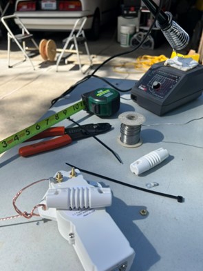
One of the simplest vertical antennas is the quarter wave. My first quarter wave antenna was a 5-meter radiator wire (one-quarter the length of 20 meters) with four counterpoise wires on the ground. I attached the radiator to the center of my coax and the counterpoises to the shield. I’ve deployed the radiator vertically in a tree (great for permanent setups) and supported it with a fiberglass telescoping fishing pole (ideal for portable use).

While these antennas are simple to build, I prefer an antenna that works on multiple bands and is easy to deploy and pack. This is why I’m a big fan of the Chelegance MC-750 .

portable ham antenna set up near riverbank
Chelegance MC-750 Portable HF Vertical Antenna (Image/Thomas Witherspoon, K4SWL)

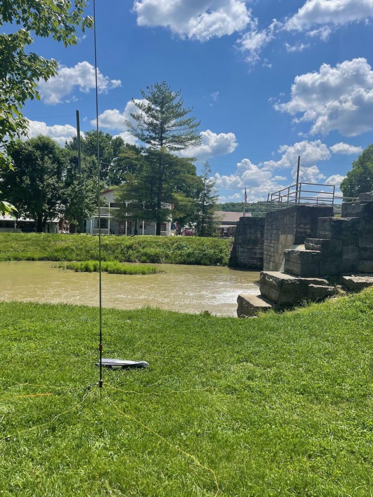
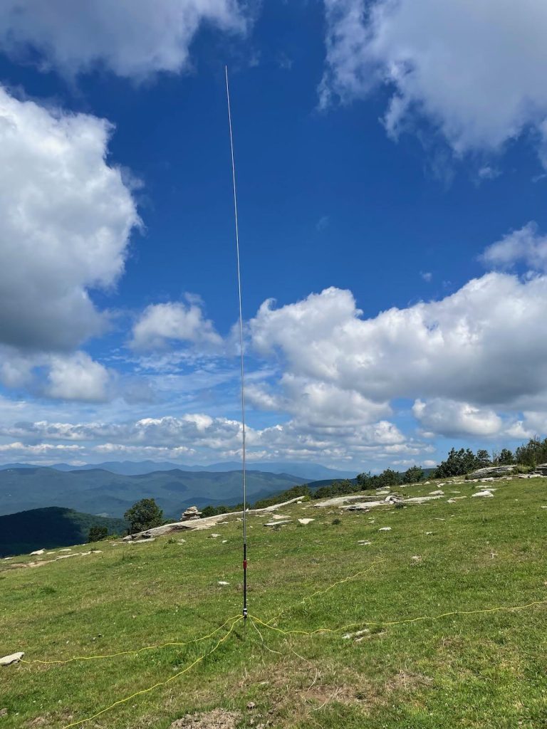
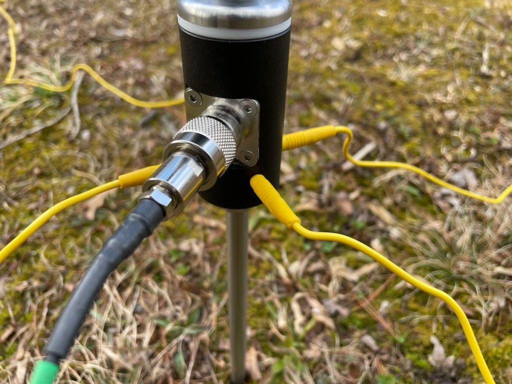
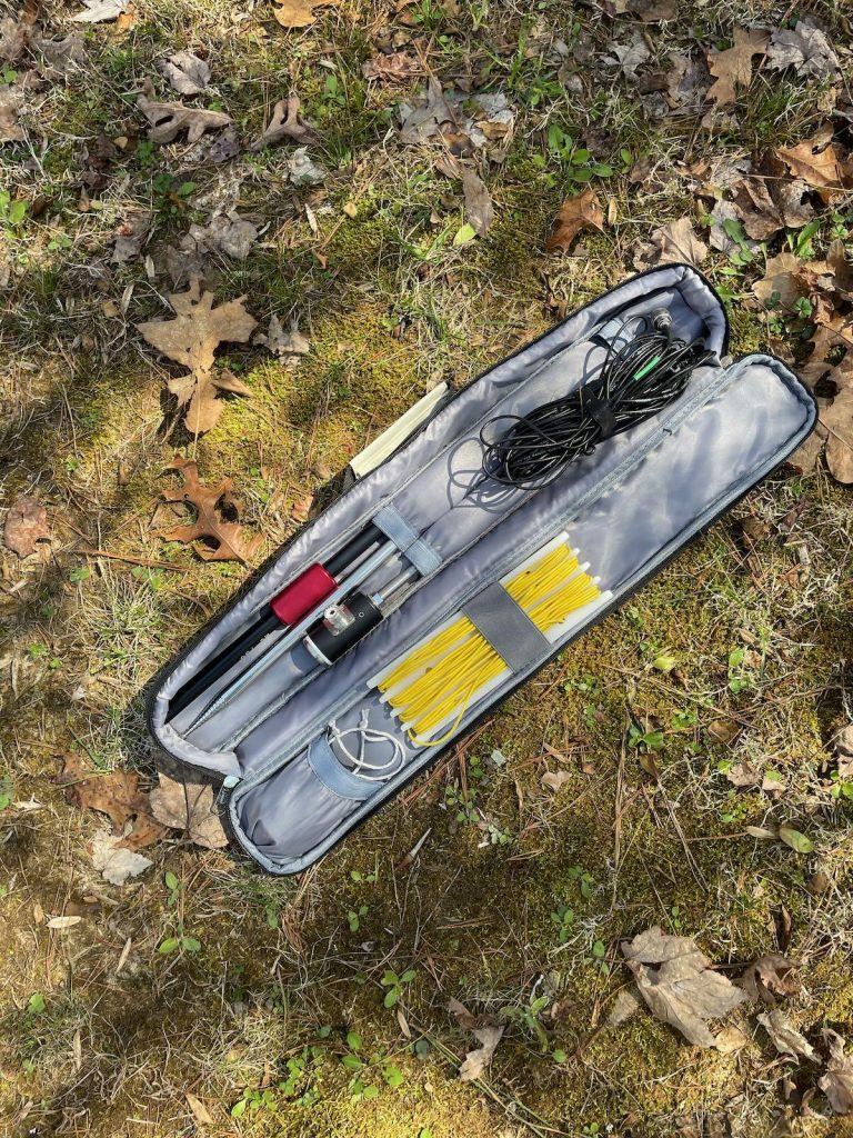
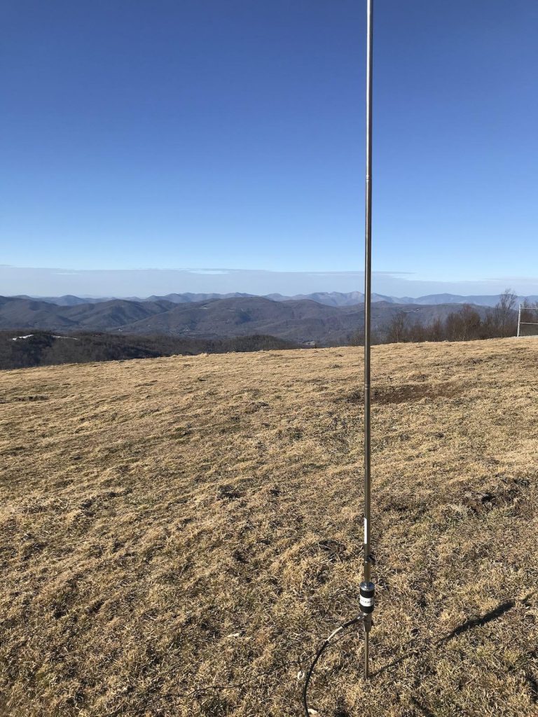
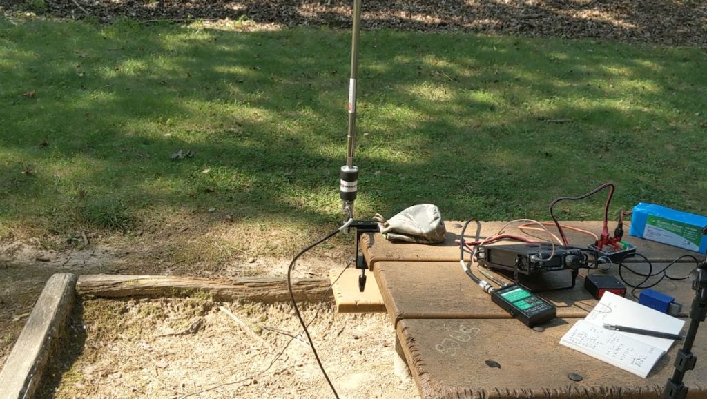
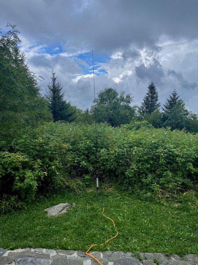
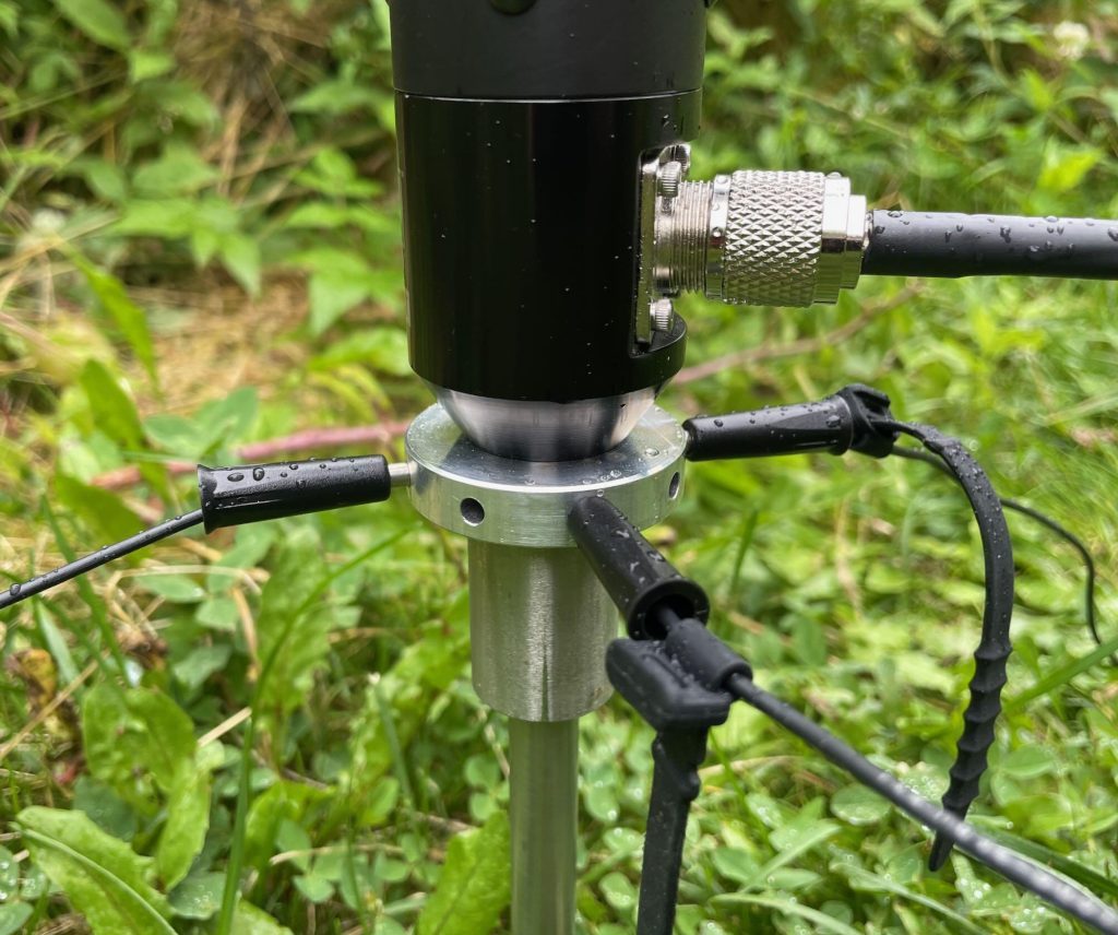
The MC-750 is a portable vertical deployed using either a stainless ground spike or a tripod. The vertical element is a stainless steel whip with silk-screen markings that help you deploy the antenna for resonance on multiple bands.

close up of a telescoping radio antenna joint
(Image/Thomas Witherspoon, K4SWL)

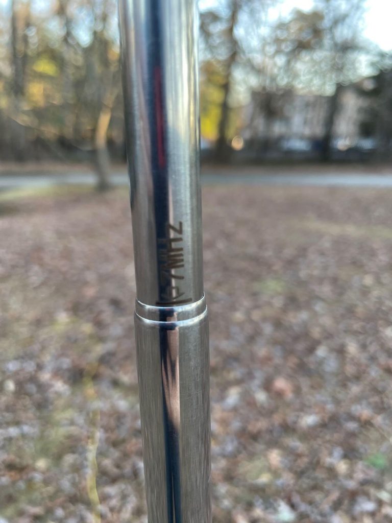
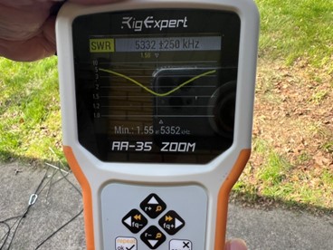
When I follow the silk-screen markings and all four counterpoise wires (attached to the base), I consistently achieve a near 1:1 SWR. Thus, no ATU is needed. The SWR remains consistent across various topographies.

radial wires and RF connector on a portable antenna
The Chelegance MC-750 comes with jacks to install four included preassembled counterpoise radials. (Image/Thomas Witherspoon, K4SWL)
portable ham radio antenna in bag
Chelegance MC-750 carrying case (Image/Thomas Witherspoon, K4SWL)

The MC-750 ships with a coil for 40 meters. Chelegance also offers an optional 80 meter coil as well.

  • Pros: Easy deployment, high quality, efficient, multi-band use with no ATU needed, resonates on 20-10 meters and 40/80 meters with coils, comes with a custom padded carrying case. 
  • Cons: Not truly a con, but you must adjust the whip length when changing bands if not using an ATU.

***

2. Verticals with Transformers

portable ham radio antenna set up in a field
Chameleon CHA MPAS Lite Modular Portable Antenna (Image/Thomas Witherspoon, K4SWL)

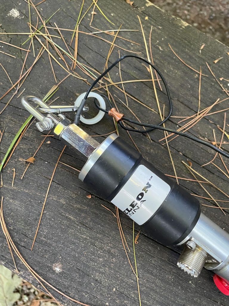
If you regularly use an antenna tuner in the field, you might prefer a high-quality multi-band vertical antenna equipped with a transformer to reduce potentially high impedances to a level manageable by most tuners. I think of this type of antenna as the vertical equivalent of a random wire antenna. Many of my QRP transceivers have internal ATUs, making this type of antenna very appealing. The one I have the most experience with is the Chameleon CHA MPAS Lite.

Like the MC-750, the MPAS Lite uses a stainless steel whip but includes a transformer at the base, making it easier to match the antenna across multiple bands with virtually any ATU. Additionally, it can operate on lower bands, including 80 meters, without needing a loading coil attached. While not as efficient below 30 meters, it remains highly effective for both POTA and SOTA where you are often the DX.

portable ham radio antenna set up over mountain range
(Image/Thomas Witherspoon, K4SWL)
portable ham radio mounted to a picnic table
(Image/Thomas Witherspoon, K4SWL)

The MPAS Lite offers excellent frequency agility, which is a major advantage if you frequently hunt or chase other stations in the field. Just change the frequency, activate the ATU, and you’re set.

close up of ham radio antenna base on table
(Image/Thomas Witherspoon, K4SWL)

The MPAS antenna can also be configured as an end-fed random wire using the counterpoise wire. Consult the MPAS Lite manual for multiple configurations.

  • Pros: Easy deployment, high quality, multi-band use, frequency agility, only one counterpoise, versatile platform for multiple antenna configurations. 
  • Cons: Pricier than the MC-750.

***

3. Loading Coil Verticals

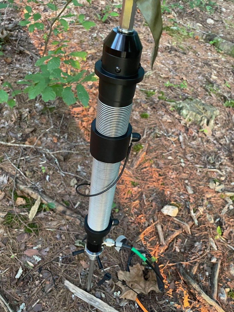
I’ve used several antennas with helically wound coils and a sliding tuning coupler at the base to match the antenna across multiple bands. The coil at the base shortens the antenna electrically, making it portable and low profile—ideal for stealthy use or in neighborhoods with aggressive HOA restrictions.

Among the many coil antennas available, the new REZ Antenna Systems Ranger 80 stands out for its robustness. I was impressed with its ease of setup, high quality, and smooth tuning coupler. The REZ Ranger 80 antenna also handles higher power than other coil systems—100 watts CW/digital and 200 watts SSB.

ham radio antenna installed near a forest
REZ Antenna Systems Ranger 80 HF Portable Antenna System (Image/Thomas Witherspoon, K4SWL)
Radio wires plugged into an antenna base
(Image/Thomas Witherspoon, K4SWL)

The Ranger 80 is quick to deploy and incredibly durable. While I’ve never been a big fan of verticals with loading coils and sliding tuning couplers, as they can be finicky to tune, I found the REZ Ranger 80 to be the best of the bunch and more forgiving than others I’ve used.

base loading coil for a ham radio antenna
(Image/Thomas Witherspoon, K4SWL)
  • Pros: Easy deployment, superb quality, higher power handling capacity, multi-band resonance, no ATU required. 
  • Cons: Heavier than other options, tuning coupler needs adjustment for each band change, pricey.

***

Summary

Choosing the right portable vertical antenna is more about matching your equipment to your specific operating style than simply selecting the most capable model. Whether you prioritize ease of deployment, frequency agility, or power handling, the antennas discussed—like the Chelegance MC-750, Chameleon CHA MPAS Lite, and the REZ Ranger 80—offer distinct advantages that cater to different needs.

Before making your decision, consider the nature of your operations. Are you regularly chasing signals across multiple bands, or do you prefer to set up and stay on one frequency? Do you need a lightweight, portable solution for long hikes, or are you more concerned with stealth and ease of use in restricted environments? Your answers will guide you to the right antenna.

Ultimately, the best antenna is the one that enhances your enjoyment of the hobby, allowing you to operate confidently and efficiently in your chosen environment. If possible, try before you buy—borrowing from friends or club members can provide valuable insights that specs alone can’t offer.

The post Ham Radio Tech: Choosing a Portable Vertical Antenna that Matches Your Needs appeared first on OnAllBands.

Ham Radio 101: A Few Basic Tips on Building Wire Dipoles

Single-band wire dipoles are one of the easiest antennas to make.

But just because they are easy to make doesn’t mean they do not work well. In fact, single-band wire dipoles outperform many antennas in many circumstances.

workbench with soldering iron & antenna parts
(Image/Elizabeth Klinc, KE8FMJ)

You will need these supplies to build your dipole:

  • Roll of wire
  • Measuring tape(s)
  • Wire cutters
  • Balun
  • Insulators
  • Solder (optional)
  • Antenna analyzer
  • Cable ties

You can use many different kinds of wire. Some people have used string soaked in saltwater! However, copper or copper-clad steel wire is generally considered the best. Stranded wire is generally better since solid wire can stretch under tension.

workbench with notepad and calculator
(Image/Elizabeth Klinc, KE8FMJ)

So how long do you need the wire to be?

From the OnAllBands article, “How High Should My Dipole Be”:

“The half-wave dipole is two equal lengths of wire with the feedpoint in the center. Each wire, or element, is a quarter wavelength of the frequency you want to transmit on. The basic formula for dipole construction is dividing 468 by the desired resonant frequency, in MHz. As an example, a dipole cut for 14.225 MHz SSB is 468/14.225 = 32.9 feet total length. Divide 32.9 in half, and we see each element of this dipole needs to be 16.45 feet long.”

There are other factors to consider when determining dipole length, such as proximity of the ground and other nearby objects. Because it’s difficult to find the ideal length before actually hanging the wire, it is always best to start any wire antenna slightly longer than the calculations might indicate and then shorten the antenna, measuring its performance each time.

homemade dipole antenna resting on grass
(Image/Elizabeth Klinc, KE8FMJ)

Now you have calculated this number. This is the length of wire you need on BOTH sides of the balun. Some of these wires are really long! How on earth do you measure and cut a wire that long?

Find a long, straight area. Roll out a heavy-duty measuring tape that will mark how long you need the wire to be. When my Elmer and I did this, we stuck a broomstick in the roll of wire and set both ends of the stick on different chairs. Next, as one held it steady, the other walked the wire out to the length of the rolled-out measuring tape.

Tie, solder, crimp, or any combination of these to each side of the balun. Short for “balanced to unbalanced,” a balun is a device used to convert a balanced signal to an unbalanced one.

For a good explanation of what that means, visit this OnAllBands article,“Baluns vs. Impedance Transformers.” Also check out this article from Moonraker, “What Is a Balun? Why You Need One and When to Use It.”

Attach your feedline to the balun. Attach insulators at the non-balun ends of the wire. This will help you hang your wire dipole without worrying if something is touching the ends of the antenna, causing your readings to be off.

rigexpert antenna analyzer display screen in use
(Image/Elizabeth Klinc, KE8FMJ)

Measure the SWR of the antenna. It is easiest to do this with an antenna analyzer with a graph display of SWR and frequency like those from RigExpert. If the SWR dip in the graph is at a lower frequency than the one you wanted, then your antenna is too long and you need to remove some of the wire. Clip very small amounts of wire from each side and take a lot of SWR readings. If the lowest SWR reading is at a higher frequency than your intended frequency, your wire is now too short.

Editor’s note: For more information on dipoles, read these OnAllBands articles:

Also, if you’re not inclined to collecting all the pieces and parts to build your own dipole, DX Engineering has taken care of it for you with their Single-Band Dipole Kits, which include:

Questions? Share them in the comments below or email me at KE8FMJ@gmail.com.

The post Ham Radio 101: A Few Basic Tips on Building Wire Dipoles appeared first on OnAllBands.

Ham Radio Tech: RF Ground—The Un-Ground

When it comes to ham radio, there are grounds…and then there are grounds.

Here are three types we typically find with radio systems:

  1. Safety ground
  2. Lightning ground
  3. RF ground

Safety grounds protect you from a shock hazard. The ground wire in your AC wall outlet is connected to a grounding rod driven into the earth by way of the entry panel. This provides a low-resistance path to dissipate any fault current safely.

Lightning/surge protection grounding works by routing voltage surges and spikes away from protected electrical devices. Devices such as lightning arresters are often installed on feed lines entering your shack and will direct surges to a ground rod.

Understanding RF Ground

RF ground is not the same thing as an electrical or lightning ground. The term is a misnomer—it really isn’t a ground at all. You know the dipole antenna is a half-wave long—two quarter-wave sections. If you have a quarter wave vertical antenna, it’s a monopole, which is actually half of a dipole. The RF ground makes up the other half of the dipole—you can provide this second half by adding radials to the antenna, or just a single elevated counterpoise wire that’s about a quarter wave long.

In a typical HF mobile setup, the vehicle is capacitively coupled to the ground, so the antenna is a cross between a lopsided vertical dipole—the whip being one side and the car body on the other—and a vertical with an elevated radial system.

Mobile Radios

Mobile installations present significantly more challenges than simply adding radials to your yard. The other half of the dipole is a random vehicle, a large chunk of metal of various sizes and configurations serving as a moving ground plane for your vertical antenna. The ground plane provides for return currents to the antenna and is an integral part of the vehicle antenna circuit.

One way to think about a ground plane is that it acts as a “mirror” for the active vertical element. As long as a mirror is big enough, you’ll hear your reflected signal from a distance. It doesn’t really matter if the mirror is circular, rectangular, or square. 

If the vehicle ground plane is lossy (which will happen to some extent), the performance of your antenna will suffer due to reduced current flow. Ground plane losses only add to existing losses from coil-loaded, physically shortened antennas typical of most mobile HF stations. It’s important to do what you can to minimize ground losses by improving the ground plane. Decreasing ground losses by just one ohm can make a significant increase in ERP (effective radiated power).

VHF/UHF mobile antennas have less ground losses if properly installed since their other half (vehicle ground plane) is sufficiently large for these frequencies

Bond, Frames Bond

Using the mirror analogy, a car is more like a collection of reflective tiles rather than a one-piece rectangular mirror hanging on the wall. Making the car work as a good signal reflector requires bonding.

Bonding is making low-impedance connections among the various conductive parts of your vehicle. The low impedance part is in the form of a conductive strap, such as a tinned braid, that is solidly attached between frame and body parts of the vehicle. Remember, the goal is to electrically join these surfaces into a single massive ground plane under the antenna and to improve the conductivity at RF frequencies. For larger gaps, one-inch-wide braid is a better solution, but keep it as short as possible. This helps it provide a low impedance connection.

For example, by using tinned braid you can electrically bond your exhaust pipe to the vehicle frame at several points along its length. Attach the braid to the pipe using ring clamps, screws with star washers, and soldered ring connectors to make a good connection to the car body or frame.

DX Engineering has a complete kit for exhaust bonding (below).

exhaust clamp and ground braid bonding strap kit dxe-egk-250_xl
An exhaust pipe directly bolted to the engine can be excited just like an antenna, radiating pulsing noise. An exhaust grounding system, like this kit from DX Engineering, can help eliminate noise from your mobile installation. (Image/DX Engineering)

Tinned braid is also suitable for bonding hood and trunk lids as well for enhanced ground plane performance. The hinges of trunks and hoods may not provide sufficient electrical connectivity for an effective ground plane. On pickup trucks, you can improve the ground plane by bonding its bed to the cab with braid beneath the truck using existing bolts and connection points. 

Important! When installing your antenna, be sure that the antenna mount provides solid continuity between the antenna ground side/coaxial shield and your newly bonded ground plane. Permanently mounted antennas using bolts and washers are usually best for electrical continuity, as long as they are mounted to a portion of the vehicle that’s part of the overall ground plane.

Using magnetic-mounted HF antennas will often result in poor grounding continuity for the antenna. At the very least, provide an additional ground braid for mag-mounts. Also, install your antenna as high as possible on the vehicle, with as much metal under the antenna as possible.

When improving a ground system, the main benefit by far is for transmitting. However, an improved ground plane with reduced losses helps to boost the received signal strength, thus improving the signal-to-noise ratio in your receiver.

Down to Earth

Moving from a rolling to a stationary RF ground plane, does efficiency increase or decrease with the number of wire radials?

Hams usually agree more radials on the ground are better, and it’s better to have more short radials than a few long ones. There has been a lot of debate about the extent of a radial system that might be needed. Based on a 1937 study, the FCC has suggested that a radial system consisting of 120 radials, each around 0.5 wavelengths long, would make an almost perfect ground system providing near 0 dB power loss at a low angle of radiation and a feed impedance of 35 ohms. It became the magic number for radial systems. However, such a radial system is impractical for most of us, especially on 80 and 160 meters.

dx engineering radial plate with radial wire installed
The patented DX Engineering Stainless Steel Radial Plate with 60 pre-drilled holes provides a neat and effective way to connect those essential radial wires and the coax to your vertical antenna. (Image/OnAllBands)

Sometimes you have to make a size compromise. The ARRL Antenna Handbook provides some figures for alternative configurations:

  • 16 radials of 0.1 λ gives a feed impedance of 52 Ω and a power loss of 3 dB
  • 36 radials of 0.15 λ gives a feed impedance of 43 Ω and a power loss of 1.5 dB
  • 60 radials of 0.2 λ gives a feed impedance of 40 Ω and a power loss of 1 dB

As we move toward 60 radials, diminishing returns kick in and the improvement gets progressively smaller. You’ll need to consider the cost of wire and the effort involved when deciding how far you’ll go.

There are other factors to consider, including local earth conductivity. The better the earth’s conductivity in a given region, the better the earth connection will be. It’s difficult to get a sufficiently good antenna RF ground plane on a rocky base. However, areas with moist soil provide a much better ground system. One of the best environments for a good ground connection is a salt marsh. This 1975 FCC Ground Conductivity map provides information about conductivity by region throughout the U.S.

There have been long-running discussions about the effectiveness of a vertical with an elevated ground system compared to one using a large number of radials on the ground surface. NEC modeling has shown that an antenna with four elevated λ/4-radials under ideal conditions would be as efficient as one with 60 or more λ/4 ground-based radials. In reality, you’ll probably need a few more than four.

The Ground That Isn’t Grounded

It acts as a reflector. It doesn’t radiate RF energy; it mirrors and reflects the energy. It also has a second purpose of providing the return path for RF current in unbalanced antennas.

No ground rod is involved, just lots of metal directly under a vertical antenna.

The post Ham Radio Tech: RF Ground—The Un-Ground appeared first on OnAllBands.

Doing a Good Turn: Choosing the Right Rotator for Your Amateur Radio Station

A rotator is a handy device used in ham radio communication systems to change the orientation of an antenna. Rotators have two parts, the rotator unit and the controller. The controller is normally placed near the radio equipment, while the rotator is mounted on the antenna mast below the antenna. It’s a must-have for DXers and operators who want to extend their reach and improve reception.

Is it Rotator or Rotor?

Let’s settle this before we move on. Hams tend to use both words interchangeably, but there is a subtle difference.

  • A rotator is a device, such as a motor, that makes something rotate—like a mast with a Yagi attached.
  • A rotor is a part of a device that rotates, such as a brake rotor or armature.

How Does an Antenna Rotator Work?

The rotator is typically mounted on the antenna mast or inside the tower, directly below the antenna, while the controller is usually placed in the ham shack near the operator’s position. The controller sends signals to the rotator unit, instructing it to rotate to a chosen heading.

Modern rotators are generally small. Due to gear reduction, the motor mechanism can be relatively compact and not draw much current. Large rotators have bigger motors, but the increase in strength is mostly due to improved gear and brake systems. The power required to turn even those big, stacked arrays is not that much.

To keep rotators from twisting in the wind, they include a braking mechanism. Smaller ones use a friction disc arrangement—when the rotator turns, the discs move apart to let the mast turn freely. When power is removed, the discs clamp together again. With medium-sized rotators, brakes consist of a heavy-duty solenoid with a spring-loaded wedge or bar that fits into indentations inside the rotating housing. On big rotators, worm gears are used and braking is done by the resistance to the gears turning backward under load.

Rotators are designed to turn a full 360 degrees, and often a bit more. That is known as overlap. At the ends of rotation, mechanical limit switches open to remove power from the motor. It’s important to leave a rotator loop in your feedline during installation to prevent stretching or breaking your feedline.

Choosing the Best Antenna Rotator

Durability is important, especially for something that’s exposed to the elements. Look for sturdy materials which can endure outdoor conditions without corroding or deteriorating over time. Opt for models with a sealed housing to protect internal components from moisture and dust for long-term reliability and performance.

Make sure the rotator you choose is compatible with your specific setup. This includes assessing antenna size, weight, and mounting considerations. There’s nothing more annoying than finding that your rotator won’t fit properly inside your tower. Also verify compatibility with any existing hardware you plan to use, such as controllers, accessories, and mountings.

It’s important not to overload a rotator. If you live in a location that’s subject to high winds, continuous winds, or large gusts, look at the wind load recommendations included with the unit. These are usually specified as a maximum antenna area in square feet or square meters. Add all of their wind load numbers together for several antennas on a single mast, and don’t forget the mast’s wind load. You can find your antenna’s specs in the manual or online.

A rotator can handle a larger wind load when mounted inside a tower section, as opposed to mast mounting, since the tower holds the mast in place straight above the rotator. Using a thrust bearing keeps most of the load off the mast, further increasing wind load capabilities. Inside tower mounting eliminates any sideways load on the rotating assembly relative to the base.

antenna rotator instructions
Mounting the rotator on a pole or mast limits the antenna’s size and the mast’s length from the rotator to antenna. This is due to the significant bending forces applied to the rotator’s clamps. Mount the antenna as close to the rotator as practical in this configuration. (Image/DX Engineering)

In the preferred tower-mounting configuration, a sleeve bearing provides additional support. Another option is using a thrust bearing at the top, which transfers the weight of the antenna and mast onto the tower and off the rotator. The rotator then just turns the antenna without the extra load.

Controlling the Rotator

Each manufacturer of rotator/controller combinations has its own design of control boxes for controlling the rotator and displaying antenna position. Yaesu’s desktop controllers provide a round dial with a 360-degree radial indication of antenna azimuth bearing. Hy-Gain HAM-IV and CD-45II models include a more traditional analog meter readout with N/S/E/W markings and azimuth readings in five degree increments.

There are also aftermarket control units that operate with many different rotators. These include the Green Heron RT-21 Series Digital Controllers and the EA4TX ARS-USB Rotator Controller with digital readout. The coolest of the group is the microHAM ARCO Advanced Rotator Controller (below) with touchscreen LCD control and azimuth information superimposed on a world map display.

moh-arco-115v_hu_xl rotator controller
(Image/DX Engineering)

If you’re old school, you may want to control your rotator manually with the clockwise/counterclockwise buttons or do point-and-shoot using the preset dial. If you plug in the call sign of a station, most logging programs will provide you with the short path and long path settings you’ll need.

Newer rotator controllers may have an interface—either RS-232 or USB. Some controllers can be connected directly to your PC to operate your unit. Older controllers may require an additional interface board that can be installed inside the rotator control box. For example, programs like PstRotator and DX-Lab can directly calculate the beam direction for long and short path and pass it on to the rotator control. Many of the popular logging software programs can also control a rotator with the help of a PC. The Ham Radio Deluxe Software suite for Windows includes the HRD Rotator Control module, which manages beam headings via any computer-interfaced rotator controller.

Interested in space? An antenna rotator with both rotational and elevation controls, like the Yaesu G-5500DC (plus related software), is essential for ham radio satellite, ISS, and EME (moonbounce) communication. It enables users to accurately track satellites and the ISS as they move across the sky. Such equipment can make adjustments quickly, maintaining a solid connection for communication.

What’s Right for You?

Decide what antenna(s) you plan to put on your mast or tower and calculate the total wind load. It doesn’t hurt to go a bit larger on your rotator. You’ll have some additional headroom and prepare for the possibility of an antenna upgrade or added antenna later on. It’s difficult to change out rotators on a tower—I know from experience.

Rotator packages usually include the necessary connectors. You’ll need to supply the wiring between the controller and the rotator, usually a six- or eight-conductor for ham rotators and three- or four-conductor for TV/light-duty rotators. They can be purchased by the foot or as ready-made cables. Other items to consider include thrust bearings and rotator shelves inside tower mounts, like the DX Engineering Accessory Shelf below for Yaesu and Hy-Gain rotators.

dxe-as25g_xl acessory shelf
(Image/DX Engineering)

Light-Duty Rotators

For smaller VHF/UHF Yagis and rotatable dipoles with wind loads >3 sq. ft. Mast/inside tower mount.

  • Hy-Gain AR-40, AR-500

Medium-Duty Rotators

For Hexbeam, tri-band 3-element monoband Yagis, and larger VHF/UHF arrays with wind loads of 8-10 sq. ft. Inside tower mount.

Medium/Heavy-Duty Rotators

For multi-element Yagis with wind loads of 15-22 sq. ft. Inside tower mount.

Heavy-Duty Rotators

For large Yagis, multiple Yagis with wind loads to 35+ sq. ft. Inside tower mount.

Editor’s note: The DX Engineering RT4500HD rotator comes in combos which include rotator and 2-inch or 3-inch mast clamp; rotator, clamp, and ARCO controller (below); and rotator, clamp, and DX Engineering controller.

dx engineering rotator and controller combo contents
(Image/DX Engineering)

The post Doing a Good Turn: Choosing the Right Rotator for Your Amateur Radio Station appeared first on OnAllBands.

My Weather Station on Apple Watch

Weather tracking has been a hobby of mine since childhood, and I’ve owned many weather stations over the years from Peet Brothers to Davis to now, happily, Ambient Weather.

One thing I’ve been looking for is a way to view my weather station stats on my Apple Watch. Thanks to a tip on a Weather Facebook group, I now have it! The myPWS app is working great.

In the first photo, the lower right temp is my weather station, while the upper right is my current location. Click on the lower right, and you see more scrollable info.

Apple Watch

myPWS scrollable display

Tech I Can’t Live Without: Tile

How often have you misplaced your keys? Your checkbook? Your wallet? And doesn’t this usually happen when you’re in hurry?

I’m in the same boat, but I’m here to extoll the praises of a clever piece of tech that has come to my rescue. It’s called Tile, and I can’t even count the number of times it has come through for us since its release in 2014.

IMG_2167At about 1.5 inches square, it’s easy to hang a Tile on your keychain, pop one in your checkbook and stash one in your wallet or purse. Load the Tile application on your Android phone or iPhone and you’re in business!

The Tile uses low power Bluetooth technology so that, if your valuable is misplaced, you can find it using the Tile app. The range is about 100 feet, and as you get closer, the concentric rings on the app’s screen get darker (like RADAR!)  When you initiate a Find, the app also instructs the Tile to initiate an audible alert. This really helps when your keys have fallen behind a couch cushion or under the driver’s seat!

If that Tile is out of range, the application will display the place it last “saw” it. You can then mark it as “lost” on the app. If any other Tile user comes within range, an anonymous message will be relayed back to you with its updated location (the other Tile user is not informed).  In a rural area, that might not help. but there a thousands of users here in Dallas.

Here’s another cool feature – let’s say you have your keys but can’t find your phone.  Not a problem. Click the button on any Tile three times and your phone will start playing the Tile tune, making it easy to find.

Until late 2018, there was one significant drawback to the Tile – the battery in each device would only last a year and was not replaceable.  That’s no longer the case, as the newest Tile models each have a user replaceable, inexpensive coin sized battery.

At $25 to $35 each, the Tiles are not inexpensive, but, for me, they are definitely worth the price! The Tile is a device I can’t live without.

http://www.thetileapp.com


About That UHF Connector

I caused a minor kerfuffle on Twitter recently, when I posted this:

This connector, properly called a PL-259, is the most common RF connector for ham radio use. The female counterpart is called the SO-239 connector. While these connectors are often “UHF” connectors, they actually don’t perform very well at those frequencies (300 to 3000 MHz). So I feel justified in disparaging that name.

The tweet generated a large number of replies, mostly in support of my anti-UHF-naming sentiment. It seems that other highly-educated and thoughtful radio amateurs agree with me. (It seems that the wise hams out there always agree with me.) You should be able to view the thread here: https://twitter.com/K0NR/status/1653575723838492672

Some people pushed back on the anti-UHF sentiment, usually saying that it is the common name for this connecter. A few folks pointed out that Amphenol calls these things “UHF Connectors”, which did surprise me. Who am I to disagree with this manufacturer of high-quality connectors? Of course, Amphenol also says this:

Originally intended for use as a video connector in radar applications, UHF coaxial connectors are general purpose units developed for use in low frequency systems from 0.6 – 300 MHz. Invented for use in the radio industry in the 1930’s, UHF is an acronym for Ultra High Frequency because at the time 300 MHz was considered high frequency. They can be used when impedance mating is not required.

Well, there you have it: the connector was named UHF back when UHF meant up to 300 MHz. (Today, UHF means 300 to 3000 MHz). I particularly like the comment “They can be used when impedance mating is not required.” What? That does not sound good for RF applications. I do agree that these connectors can generally be used to 300 MHz, but these days the ITU calls that VHF (30 to 300 MHz).

Wikipedia provides a more complete explanation, worth reading.

OK, so the name “UHF” is archaic but it has kind of stuck, the way old terminology sometimes does. I am still going to avoid using this term because it really should be deprecated.

And don’t use these connectors above 300 MHz (UHF frequencies). Unless you have to. Which I did last weekend when the only cable available for my 440 MHz antenna had a PL-259 connector on it.

73 Bob K0NR

The post About That UHF Connector appeared first on The KØNR Radio Site.

❌