This is the second installment of a two-part article about RF when you are operating “in the field,” meaning away from a fixed station.
For example, when you are operating a portable station for Parks On The Air (POTA), that’s considered “in the field” whether you are in an actual field or a parking lot or not even outside. Field Day certainly qualifies in most cases. In both parts of this article, the RF from your transmitted signal is what we’re concerned with.
Mechanical Concerns
We can start with some non-RF considerations that are certainly related to antennas, but not the radiated RF.
Most antennas used in the field are either ground-mounted or lower in height than at a fixed station. This, combined with the likelihood of their being in a public space, presents a variety of hazards to passers-by and other visitors. Your goal is to keep people from walking into, tripping over, touching, or otherwise getting too close to the antennas and feed lines.
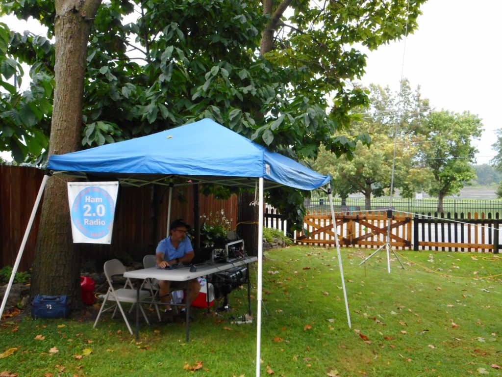
The photo below shows a typical portable station with a table, tarp, and temporary antenna about 20 feet away in the background.
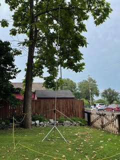
Carl, AE0CJ, and I operated from the grounds of Missouri’s first capitol to celebrate the state’s bicentennial. Note that the tripod-mounted antenna takes advantage of the property fence to help keep other visitors from getting too close. Below is another photo of the antenna. (Image/Ward Silver, NØAX)(Image/Ward Silver, NØAX)
You can see the yellow rope placed around the antenna as a warning not to get too close. Plastic fence posts were used to hold the rope. Yellow caution tape is inexpensive and even more visible. Remember that many parks prohibit sticking anything in the ground, even for safety. In such cases, orange traffic cones are a good compromise.
Feed lines and power cords present a tripping hazard to both visitors and operators. If allowed, a stake in the ground next to the cables with a bit of yellow caution tape marks their location and can secure the cables. I always tie or secure the cables to a table leg so that if something does happen, the equipment is not dragged off onto the ground. (Don’t ask me how I learned to do this…)
Finally, don’t install your antenna where it can come in contact with vegetation. The end of an antenna element can present fairly high RF voltages, even at 100 watts output. This is enough to heat up leaves to the point where they will catch fire or at least smolder. Starting a fire is a definite no-no! (Don’t ask me how I learned this, either…)
Choose Your Words Carefully
Before we go any further, I need to remind you that the word “radiation” when referring to our transmitted RF may be accurate, but it is not a word the public or facility staff are comfortable with. I am careful to keep things simple and speak of “radio signals” instead of “field strength” or “radiation.” If someone asks about risks, you could truthfully tell them they might get a slight shock if they touch the antenna while you are transmitting. (If you are using an amplifier, it might be harsher than “slight,” so consider the possibilities.) Then explain that is why you have taken steps to prevent anyone from accidentally coming in contact with the antenna.
This is also a reminder to read or re-read the paragraph on preventing RF burns in the first part of this article, “RF Management—In the Field.”
RF Field Strength
The primary concern of this article is the high RF field strength near an antenna. FCC rules require us to evaluate the RF exposure from our fixed station antennas. Portable stations don’t require the same level of scrutiny, but you can use the same methods to determine whether your portable antennas might present a hazard to you or the public with respect to the Maximum Permissible Exposure (MPE).
Uncontrolled vs. Controlled
The allowed exposure levels are different for two kinds of environments—controlled (or operational) and uncontrolled (or general public). For a fixed station at our home, for example, the antennas are on private property and access to them is limited by property boundaries, fences, etc. This implies that anyone in the vicinity of the antenna either knows it is present or is there with your permission and supervision.
This is a controlled environment, and the MPE levels are higher because it is assumed the person can either take steps to stay away from the antenna or avoid being close to the antenna when the station is transmitting.
Uncontrolled environments are different and assume someone near the antenna is not aware of what it is or that it is present. They may approach the antenna at any time and are not assumed to be under your supervision, nor can they manage their own exposure.
For example, a vehicle-mounted antenna on your car in a parking lot can be approached by anyone in the lot. This is why the MPE levels are lower for uncontrolled environments. It’s safest that you assume these limits apply when considering how to construct and use your station.
High-Q Antennas
Another factor to consider is how your antenna radiates a signal and whether the RF field strength near the antenna will be particularly strong. The antenna’s ratio of stored energy to radiated energy is a measure of the antenna’s Q. Q is also known as quality factor, and for components, measures the ratio of reactance which stores energy to resistance which dissipates energy.
Antennas that store a lot of energy in the near field (within a wavelength or two of the signal frequency) can build up a surprisingly high field strength for any given power. These are known as high-Q antennas.
A high-Q antenna usually has a very low radiation resistance, which represents the antenna’s ability to radiate power into its far field, which is what launches our signals. The low radiation resistance means the antenna has to store a lot of energy for our transmitter output power to be turned into radiated signal (or heating in antenna system losses).
Imagine our antenna as a balloon being inflated by a compressor that delivers a continuous flow of air—this is our transmitter. The antenna’s radiation resistance is represented by a hole in the balloon through which air leaks out to the outside world (i.e., our transmitted signal). The balloon inflates until the amount of air leaking through hole balances the compressor’s output. The smaller the hole (the lower the radiation resistance), the higher the pressure in the balloon must be (the near field strength) for the leaking air to equal the incoming air.
The relationship between stored energy and radiated power and Q is clearly presented in a February 2013 QST article, “Q and the Energy Stored Around Antennas,” by Kai Siwiak, KE4PT. In the article, he describes and illustrates these important relationships and gives examples for real-world antennas.
For example, dipole antennas have a Q ranging from around 7 to 20, while small HF transmitting loops (a.k.a., a “magnetic” loop) can have a Q as high as 1,000. Antennas that are physically small compared to the transmitted signal wavelength generally have low radiation resistances and are high-Q.
You can tell if you have a high-Q antenna if the SWR bandwidth of the antenna is low compared to a full-size antenna. Along with the small loops, this includes popular antennas like loaded whips that are often mounted near the ground.
Tune the antenna for an SWR of 1:1 at the operating frequency. Then find the two frequencies at which SWR increases to 2.6, FU and FL. Divide the square root of FU x FL by the SWR bandwidth, FU – FL, and that will give you Q.
For example, if SWR equals 2.6 at 14.275 and 14.295 MHz, Q = 714. That’s a high-Q antenna!
Bear in mind that losses in the feed line will make SWR look a little better at the meter than it is at the antenna terminals, so the actual SWR bandwidth is smaller and Q is higher.
How Safe is Safe?
Like most questions about antenna systems, the answer always seems to begin with “It depends…” So do answers about minimum safe distances for transmitting antennas.
The answer depends on operating frequency, antenna Q, and transmitter output power. Since every portable setup is a little (or a lot) different, you can’t be modeling or making complex calculations all the time.
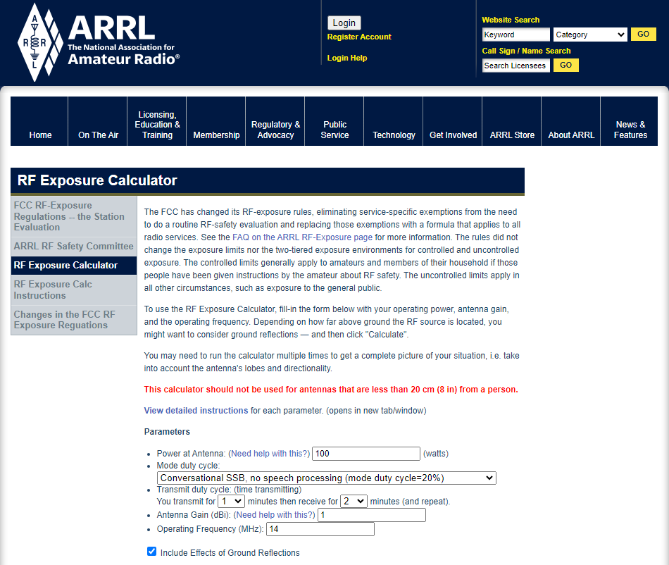
To help amateurs deal with this complexity, the ARRL provides an online RF exposure calculator.
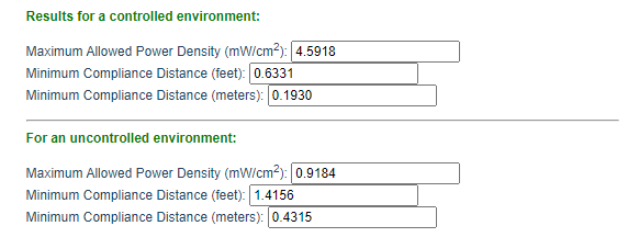
The following is a calculation for a 100-watt, 14 MHz station using unprocessed SSB with a 20% operating duty cycle and a ground-plane antenna with 1 dBi of gain.
(Image/ARRL.com)(Image/ARRL.com)
Note that it’s safe to get pretty close to the antenna. However, if I turn on speech processing or operate more aggressively, such as during a contest or POTA activation, the minimum distance will increase. Similarly, using a mode like FT8, which has a 50% duty cycle of full power on periods, will increase minimum distances still further.
This short table is an excerpt from Table 5.7 of RF Exposure and You (see this article’s conclusion for how to obtain that book) that provides typical gains for some popular portable antennas. For a vertical dipole or end-fed half-wave antenna, use the half-wavelength dipole gain. For a “hex” beam, use the two-element Yagi gain. Loaded whips are less efficient than a full-size vertical, so that antenna’s safe distances are a conservative estimate for the whip.
Typical Antenna Gains in Free Space (dBi)
Quarter-wave ground plane – 1.0
Half-wavelength dipole – 2.15
2-element Yagi – 6.0
For the special case of a small HF transmitting loop, the minimum distances are larger, due to the higher stored energy of this very high-Q antenna. Siwiak calculates these minimum safe distances in his May 2017 QST Technical Correspondence item, “RF Exposure Compliance Distances for Transmitting Loops, and Transmitting Loop Current.”
From that article, for a one-meter-diameter loop with five watts of continuous transmit power on the 40–10 meter bands, the minimum safe distance for the uncontrolled environment is 1.7 meters (5.6 feet). This increases to 2.1 meters (6.9 feet) at 10 watts output power. Table 17 from the FCC OET Bulletin 65B shows the safe uncontrolled distances for 150 watts increasing from 2.8 meters (9.2 feet) on the 40 meter band to 4.2 meters (13.8 feet) on 10 meters.
Using an amplifier, such as for a special event or contest, with a small loop increases the minimum distances on 40 through 10 meters to 17.4 feet to 42.4 feet, respectively. (A two-meter-diameter loop on 80 meters requires 21.6 feet of separation at full power.)
See Siwiak’s March 2012 QST Technical Correspondence article, “An Antenna Idea for Antenna-Restricted Communities” for more information.
Please Think About RF Safety
It’s easy to overlook these concerns in the “heat of battle” when you are just trying to get a station put together and on the air. Hopefully, this article will encourage you to consider antenna placement in the field. I see far too many pictures of portable setups where the antenna is a few feet away from a 100-watt transceiver. There are even photos of “mag loops” sitting right on a picnic table next to the operator! Don’t do that.
You can learn a lot more on the ARRL’s RF Exposure website. The excellent text reference RF Exposure and You by the ARRL’s Ed Hare, W1RFI, is downloadable at no cost as a PDF book. It has many helpful tables and examples.
I don’t think RF exposure is something we should be afraid of, but neither should we be careless in how we treat it.
This is the first of a two-part article about RF when you are operating “in the field,” meaning away from a fixed station.
For example, when you are operating a portable station for Parks On The Air (POTA), that’s considered “in the field” whether you are in an actual field or a parking lot or not even outside. Field Day certainly qualifies in most cases.
Because these are temporary situations, you have to apply a different set of techniques to get everything working and keep it working.
“RF Management”–What Does That Mean?
In both parts of this article, I’ll consider the RF to be from your transmitted signal. There is certainly RF floating around from other signals, and some might be very strong, but let’s deal with your transmitted signal here.
What does the “management” part mean, though?
I have been using the term to include all of the various techniques that are used to keep our RF where it belongs and out of where it doesn’t belong. That includes configuring your station so that it performs correctly when you are transmitting. So, we are going “manage” how your station performs when the strong RF is present.
As you’ll see, that covers a surprisingly wide range of concerns.
Where Is the RF?
Better to ask, Where isn’t the RF? That is really a better question than the first part.
We tend to think of our station as “over here” and the antenna radiating RF as “over there,” so the RF just flies away in the direction of other stations. Well, not quite. You, the operator, and your station are very, very close to where that strong RF is launched, at least electrically.
Let’s ask a question: What is the wavelength of a 40 meter signal?
Not a trick question! It’s about 40 meters, which is about 132 feet. More specifically, a 7.15 MHz signal has a wavelength of about 42 meters, which is about 137 feet.
Note that only two of the HF bands contain the wavelength by which they’re known: 160 meters at 1.875 MHz and 80 meters at 3.75 MHz.
If your 40 meter antenna is closer to you than about 1/2 wavelength, or 60-something feet, you’re right in the near field of the antenna! It takes another 100 feet or more to get you out of the strong RF field.
The resulting strength of your signal is going to be STRONG!
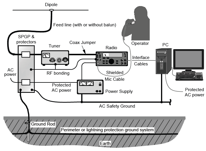
In your station, fixed or portable, everything acts as an antenna! (Graphic from Grounding & Bonding for the Radio Amateur, 2nd Edition, courtesy of the ARRL)
As a result, RF is going to be picked up by just about every bit of conductive material within 100 feet or more of the antenna. Pro tip—you are conductive as well.
Everything in your station—everything—is going to have RF voltage and RF current on it. Unless you are operating in a metal shipping container, you might as well figure out how to deal with RF.
Let’s start with your station equipment.
RF and the Equipment Table—Bonding
Take a look at your typical portable setup. There will be a radio, power supply, maybe an antenna tuner, a laptop or tablet for logging and digital modes, headphones or other audio gear, and a gadget or two. All of these are connected together with short antennas…er…wires and cables.
If you just throw everything on the table and hook it all up, there are lots of paths for RF to follow. Some might be low impedance so the RF current is high, and some might be high impedance so the RF voltage is high. The end of any unconnected wire or cable will be a high impedance point and that’s where you get an “RF burn”—on microphones, keys, and isolated metal boxes. You never forget an RF burn on your lips from touching a “hot” metal microphone!
These aren’t particularly hazardous, but they are obnoxious!
Even more obnoxious is equipment misbehaving when you press the key or mike switch. Maybe an automatic tuner decides to suddenly re-tune, a computer keyboard freezes up, or a radio changes a setting. This is caused by RF current getting into (or out of) something it shouldn’t. And what causes RF current to flow? RF voltage! More specifically, a difference of RF voltage between pieces of equipment.
If you can minimize the difference in voltage between pieces of equipment, you will also minimize RF current flowing between them along connecting cables.
That’s what bonding does for you.
If you look up “bonding” in an electrical dictionary, you’ll find that it is “a connection between two points to keep them at the same potential or voltage.” That’s all—no fancy implications or calculations. You just want to keep everything on the equipment table at the same voltage, and you do that by bonding them together with heavy wires or straps. The wires and straps should be short so they don’t have an appreciable impedance of their own.
In a portable setup, the easiest way to bond everything is to connect all of the equipment directly together. Have an assortment of jumper wires (#12-16 is good) or straps (flat tinned braid works well) that connect to screws on the metal enclosures. Powerpole connectors on the wires allow the equipment to be bonded however you arrange it. I recommend using green wire insulation and connector bodies, signifying a ground connection.
Another option is to put some aluminum foil under all the equipment and connect the enclosures to it with heavy test clip leads (#18 or heavier). The metal surface helps equalize voltage.
This is a great addition to any go-kit and has saved Field Day for me more than once.
The foil weighs hardly anything, so you can even use it for Summits On The Air (SOTA) stations carried in your pack. When you’re done, wad it up and recycle it. The foil surface should be big enough to cover a strip under all your equipment. I find a three-to-four-foot strip is more than adequate.
RF and the Station Wiring
What about all those cables connecting everything together? There are three basic techniques that will reduce or eliminate most RF problems:
Use the shortest cables you can. One-foot USB and audio cables are available.
Coil up excess cable in a figure-8 to minimize its inductance and the RF voltage it will pick up.
Use shielded cables for everything and avoid plastic, unshielded boxes for equipment enclosures.
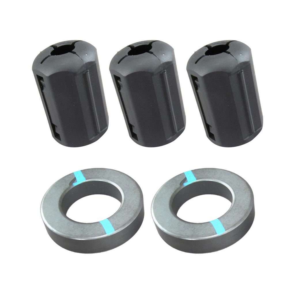
Have Type/Mix 31 (preferred) or 43 ferrite clamp-on cores available.
What is a figure-8 winding? This is a handy technique for all kinds of cable, including coax feed lines, power cables, and extension cords. The basic idea is illustrated in the last half of this YouTube video on cable winding for video work. If you practice these techniques, you’ll avoid creating a spiral twist that creates kinks. For small cables, you can wind the figure-8, then fold the two halves together. Winding half the turns in opposite directions causes a magnetic field to create equal-but-opposite voltages in the coil, minimizing RF pickup.
If you use the aluminum foil approach or have a metal table, lay the cables, including the excess length all coiled up, on the foil. That minimizes the length of cable exposed to the RF fields.
If you do need the ferrite cores, place them on the affected cable as close to the equipment experiencing interference as possible. Wind several turns of the cable onto the core before snapping it shut. Be sure both surfaces of the core are flat against each other. This creates an impedance that blocks the RF current where it is getting into the equipment.
If you’re not sure what mix makes up a “mystery core,” it’s worth buying a half dozen, then labeling or color coding them as in this photo of a ferrite core kit. The toroids can be used to wind multiple turns of coax and power cords. Snap-ons can be labeled with a permanent marker or colored tape.
(Image/DX Engineering)
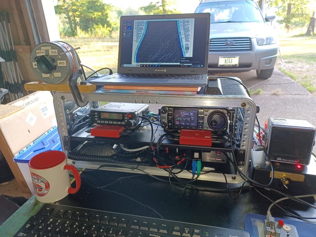
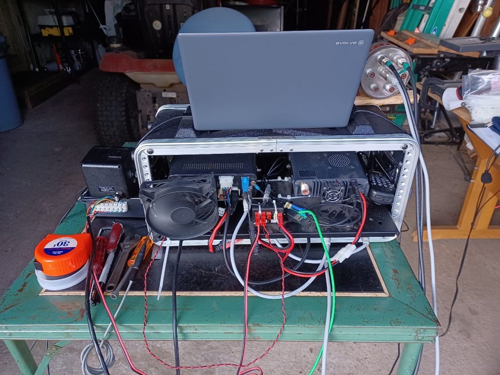
A combination approach that accomplishes bonding and keeps all of your equipment together is a portable rack. These have metal shelves and rails with an overall plastic enclosure. They’re usually available as portable audio equipment racks.
You can install all of your portable equipment more or less permanently in one of these racks. This lets you bond everything, use short cables, and debug all of the wiring so that when you take the rack of gear to the field, you know it will work with a minimum amount of setup.
True, a rack is heavier and not suitable for backpacking, but for many portable vehicle-based scenarios, it will be just fine.
These photos are from my Field Day operation in 2023 showing an IC-7000 and an FT-7900 in a standard portable audio rack. All of the equipment is bonded to the metal rack shelf. The operating table is my great-Aunt Ruth’s!
Despite your best efforts—and every field setup is different—you may find that transmitting on a particular band “lights up” the station equipment (or the operator). You might see RF interference to equipment, or a “hot spot” may cause a tingle (or more!) on some frequencies.
In this case, use a 1/4-wavelength piece of wire (calculate as 470/f in MHz–length is not critical) attached to the affected equipment on one end with an alligator clip and left open on the other. Insulate the open end.
This detuning wire will create a low-impedance point, lowering RF voltage where the wire is attached. The open end may have high voltages on it, so insulate it and don’t put it where you might touch it or step on it with bare feet! (Don’t ask me how I learned this…) Have one detuning wire for each band you plan on using.
RF on the Antenna System
Other than on the antennas themselves, as discussed earlier, RF is going to be picked up by every conductor in your station, including by the antenna feed lines as common-mode current. This is a particular challenge in mobile operation since the vehicle body is part of the antenna. The RF picked up by the feed line will flow into your station and cause problems unless you take steps to block it:
Use a common-mode choke (ferrite or wound-coax) where the feed line attaches to station equipment.
Add one or more chokes along the feed line between the station and antenna. If you are using an end-fed half-wave (EFHW) antenna, a choke at the impedance transformer may affect the antenna’s SWR. Check the antenna manual for guidance.
If you are using a vertical antenna, such as a whip with a base-loading coil close to the ground, place some chicken wire or hardware cloth under the antenna to act as a ground plane. Route the feed line underneath it to maximize the shielding effect.
If your antenna is mounted on a vehicle, bond the antenna mount to the body with a heavy wire as close to the mount as possible. This helps keep the feed line from becoming part of the antenna.
In a vehicle, operate with the doors closed to keep RF on the outer surfaces. A ferrite choke where a feed line enters the vehicle is also helpful.
Finally, what about a ground connection to the Earth itself?
Generally, you don’t need one! Most generators do not require a ground rod or connection—check the manual.
A vertical antenna will require radials or a ground screen as in item three above but does not need a direct connection to the soil. Horizontally polarized antennas like dipoles, most EFHWs, and double-whips will be de-tuned by a ground connection. In many public places, it is not allowed to drive stakes or rods into the ground.
What about lightning protection?
In a portable or mobile setup, the best advice during storms is to lower the antennas to the ground, disconnect the feed line and secure it at least six feet from the station. There is little you can do to protect your equipment from a lightning strike in the field. Take shelter yourself! If you’re in a vehicle and lightning is striking nearby, close the doors and try not to touch any metal until the storm passes.
***
This article touched on some of the important aspects of dealing with the strong RF you’ll encounter when operating a portable station. In the next article, I’ll discuss some concerns for RF safety in these setups, an often-overlooked aspect of setting up away from home.
I think the point I was trying to make about the influence of signal strength is here:
Referring to fig. 1C, note the high level of rf at the 3rd order level - typically 36-dB down. Consequently, there will be rf energy outside the normal 23 kHz passband that will be only 36-dB below the carrier peaks, or about one four-thousandth of the peak power. Not bad if the station is only 25-30 dB out of the noise, but very objectionable if it's 40-60 dB out of the noise.
I think it is supposed to read "2-3 kHz passband" vice "23kHz passband."
I guess the point is that QRP levels of operation can hide a host of ills. IMD ills. This makes me wonder about the cleanliness of my own signals. I will have to do some more careful measurements.
I finally landed at a quiet tape vs. noise configuration for TouCans on Saturday afternoon. Here’s how.
In the picture above, the wires circled in green include the + and - power wire, (white and red respectively), and the keyer wire, (also red.) When I taped the bundle of wires including the single turn coil shown in the white wire to the side of the can, the noise from the power supply went away. I was left with only noise from the radio, (the kind I want), and a gentle hum from the power supply because it had switched into buck converter mode to step its voltage up to the required 15V! The helicoptering from the Pico-W was also almost gone.
In other parts of the project, the Pico-W has started burning through pairs of AA batteries rather quickly.
At the moment, I pretty much have my HF radio on 28.1246 MHz USB all of the time listening for QSPR and QRSS signals on the 10m band. Over the last few weeks and months, I've noticed plenty of solar noise from flares erupting on the sun.
The vast majority of these hardly move the S meter on the radio, it's just that I can hear the increase in noise level. At 16:47 UTC on the 14th of May 2024, there was a huge burst of noise and when I looked, the S meter was up at S6.
The is shown in the audio spectrum display above with time moving from right to left. The sudden onset of the solar noise can be seen as a result of the flare on the sun.
I knew that this flare was a really big enough and sure enough when I checked later, it turned out to be X8.7 solar flare and the largest one so far for the the current solar cycle.
I posted on Twitter /X that a big flare had occurred and Chris, G4IFX in England noted that he had heard the same thing on the 50 MHz band.
Larry, VO1FOG in Newfoundland got a screen capture of the solar noise while listening at 92.3 MHz so it was certainly broadband as expected.
It also resulted in a big radio blackout on the HF bands. The question now is if this will result in a big aurora in the next day or two? We'll have to wait and see.
10th May 2024: I had the radio turned on in the background this morning and I noticed a large burst of noise from the sun. I had the SpectrumLab software running since yesterday and I took this screen grab.
Just to explain the image above...
1) I was listening on 28.1246 MHz USB which is the 10m WSPR & QRSS frequency.
2) Around 06:42 UTC, a meteor burnt up about 100kms above the west of England or Wales leaving an ionised trail behind. This lasted long enough that I was able to hear some of the QRSS signals from stations to the east of London, about 600kms to the east of me. The signals lasted for about a minute.
3) At about 06:43:30, the noise from a solar flare erupting on the sun reached the Earth and I heard the burst of solar noise as a loud hissing sound on 28 MHz. You can see this as the brighter colour in the image. It then faded slowly with some minor peaks over the next few minutes.
The author discusses choosing a solar charge controller suitable for radio communication. He focuses on three criteria: portability, radio frequency quietness, and Maximum Power Point Tracking (MPPT) functionality. Recommending Genasun due to its compatibility with these requirements, he mentions his dissatisfaction with another brand, Victron, that caused excessive radio frequency noise. For optimal results, he suggests keeping devices DC powered and using no inverters. He provides specific instructions about matching controllers to battery and solar panel specs, and suggests parallel configuration for Genasun controllers.
In a previous post I discussed how a band-pass "cavity" could be constructed from a chunk of 1-5/8" Heliax (tm) cable (a link to that article is here). This is the follow-up to that article.
Figure 1: The dual notch filter assembly - installed at the repeater. Click on the image for a larger version.
Notch versus band-pass
As the name implies, a "notch" filter removes only a specific frequency, ideally leaving all others unaffected while a "band pass" filter does the opposite - it passes only a specific frequency. Being the real world, neither type of filter is perfect - which is to say that the "width" of the effect of the notch or pass response is not infinitely narrow, nor is it perfectly inert at frequencies other than where it is supposed to work: The notch filter will have some effect away from its frequency of rejection, and a band pass filter will let through off-frequency energy and both will have loss even where it would not be ideal. These filters may be constructed many ways - from individual coils and capacitors to resonant structures, such as cavities - which are often larger-diameter tubes with smaller tubes inside, the latter being resonant at the frequency of interest. The cavity-type of filters often have better performance as their operation is closer to that of ideal (perfect) components.
The degree to which a filters is imperfect is significantly determined by the "Q" (quality factor) of the resonating components and in general for a cavity-based device, the bigger the cavity (diameter of conductors and the container surrounding it) the better the performance will be in terms of efficacy - which is "narrowness" in the case of the notch filter and "width" and loss in the case of the band-pass cavity.
While a cavity-based device with a large inside resonator and larger outside container is preferred, one can use pieces of large coaxial cable, instead. The use of large-ish coaxial cable as compared to smaller cable (like RG-8 or similar) is preferred as it will be "better" at everything that is important - but even a cavity constructed from 1-5/8" coax will be significantly inferior to that of a relatively small 4" (10cm) diameter commercial cavity - but there are many instance where "good" is "good enough.
Case study: Removal of APRS/packet transmitter energy from a repeater input
As noted in the article about the band-pass cavities linked above, a typical repeater duplexer - even though it may have the words "band" and "pass" on the label and in the literature - RARELY have an actual, true "band-pass" response. In other words, a true "bandpass" cavity/duplexer would have 10s of dB of attenuation, say, 20 MHz away from its tuned frequency - but most duplexers found on amateur repeaters will actually be down only 6-10 dB or so, meaning that even very far off-frequency signals (FM broadcast, services around 150-174 MHz, TV transmitters) will hit the receiver nearly unimpeded. When I tell some repeater owners of this fact, I'm often met with skepticism ("The label says 'band-pass'!") but these days - with inexpensive NanoVNAs available for well under $100, they can check it for themselves - and likely be disappointed.
Many clubs have replaced their old Motorola, GE or RCA repeaters from the 70s and 80s with more modern amateur repeaters (I'm thinking of those made by Yaesu and Icom) and found that they were suddenly plagued with overload and IMD (intermod). The reason for this is simple: The old gear typically had rather tight helical resonator front-end filters while the modern gear is essentially a modified mobile rig - with a "wideband" receiver - in a box. In this case, the only real "fix" would be the installation of band-pass cavities on the receive and transmit paths in addition to the existing duplexer.
In the case of APRS sharing a radio site, the problem is different: Both are in the amateur band and it may be that even a "proper" pass cavity may not be enough to adequately reject the energy if the two frequencies are close to each other. In this case, the scenario was about as good as it could be: The repeater input was at 147.82 MHz - almost as far away as it could be from the 144.39 APRS frequency and still be in the amateur band.
What made this situation a bit more complicated was the fact that there was also a packet digipeater on 145.01 MHz - a bit closer to the repeater input, but since it was about 600 kHz away from the 144.39 APRS frequency, that meant that just one notch wouldn't be quite enough to do the job: We would need TWO.
Is it the receiver or transmitter?
Atop this was another issue: Was it our receiver that was being desensed (overloaded) by these packet transmitters, or was it that these packet transmitters were generating broadband noise across the 2 meter band, effectively desensing the repeater's receiver?
We knew that the operators of the packet stations did not have any filtering on their own gear (the only way to address a transmit noise problem if generated by their gear) and were reluctant to spend the time, effort and money to install it unless they had compelling reason to do so. Rather than just sit at a stalemate, we decided to do due diligence and install notch filtering on the receiver to answer this question - and give the operators of the packet gear a compelling reason to take action if it turned out that their transmitters were the culprit.
A simple notch cavity:
Suitable pass cavities
are readily available for purchase new from a number of suppliers and
used from auction sites - they are also pretty easy to make from copper
and aluminum tubing - if you have the tools. Because of the rather
broad nature of a typical pass or lower-performance (e.g. broader) notch cavity, temperature stability is usually
not much of an issue in that its peak could drift a hundred kHz and
only affect the desired signal by a fraction of a dB.
As mentioned earlier, another material that could be used to make reasonable-performance pass cavities is larger-diameter hardline or "Heliax" (tm).
Ideally, something on the order of 1-5/8" or larger would be used owing
to its relative stiffness and unloaded "Q" and either air or foam
dielectric cable may be used, the main difference being that the "Q" of
the foam cable will be slightly lower and the cavity itself will be
somewhat shorter due to the different velocity factor.
Figure 2: Cutting the (air core) cable to length Refer to the calculator on the KF6YB web page, linked at the end of this article. Click on the image for a larger version.
The
"Heliax notch cavity" described here can be built with simple hand
tools, and it uses a NanoVNA for tuning and final adjustment. While
its performance will not be as good as a larger cavity, it will - in
many cases - be enough to attenuate signals that are "far enough" away for the somewhat limited "Q" of a notch filter of this construction to be effective without excessively attenuating the desired frequency.
Using 1-5/8" "Heliax":
Note:For an online calculator to help determine the length of cable to use, see the link to KF6YB's site at the end of this article.
The
"cavity" described uses 1-5/8" air-core "Heliax" - and it is necessary
for the inner conductor to be hollow to accommodate the coupling
capacitors. Most - but not all - cable of this size and larger has a
hollow center conductor. Cables larger diameter than 1-5/8" should work
fine - and are preferred - but smaller than this may not or may note be practical in situations where the notch and desired frequency are closely spaced - this, for reasons of unloaded "Q". If the center conductor is
solid or if its inside diameter cannot accommodate the coupling
capacitors (described later on) you will have to improvise their construction, using either a discrete variable capacitor or a small "sleeve" capacitor - external to the piece of cable similar to the coupling capacitors described below.
Preparing the "shorted" end:
For 2 meters, a piece of cable 18" long was cut. For cables with an air dielectric, it's recommended that one cuts itgentlywith a hand saw rather than a power tool as the latter can "snag" and damage the center conductor.
Figure 3: The "shorted" end of the stub with the slits bent to the middle and soldered to the center conductor. This end should be covered with electrical tape and/or RTV/silicone to keep out insects/dirt. Click on the image for a larger version.
For the "cold" (e.g. shorted) end, carefully (using leather gloves) remove about 3/4" (19mm) of
the outer jacket and then clean the exposed copper shield with a wire
brush, abrasive pad and/or sand paper. With this done, use a pair of
tin snips cut slots about 1/2" (12mm) deep and 1/4" (6mm) wide around the perimeter. Once this is done, use a pair of needle nose pliers and remove every other
tab, resulting is a "castellated" series of slots. At this point,
using a pair of diagonal pliers or a knife, cut away some of the inner
plastic dielectric so that it is about 1/2" (12mm) away from the end of the center conductor.
Now,
clean the center conductor so that it is nice and shiny and then bend
the tabs that were cut inwards so that they touch the center conductor.
Using a powerful soldering iron (I used a 150 watter) or
soldering gun - and, perhaps a bit of flux - solder the shield tabs to
the center conductor all of the way around. It's best to do this with
the section of coax laying on its side so that hot solder/metal pieces
do not end up inside the coax - particularly if air-core cable is used.
If you used acid-core flux, carefully remove it before proceeding.
With
one end of the cable shorted you can trim back any protruding center
conductor and file any sharp edges - again taking care to avoid getting
bits of metal inside the air-space of the cable or embedded in the foam. At some point,
you should cover the shorted end with RTV (silicone) and/or good-quality electrical tape to prevent contamination by dust or insects.
Preparing the "business" end:
Figure 4: This shows how the tube for the coupling capacitor is placed. This photo is from the band-pass version with two tubes. Click on the image for a larger version.
At
this point, the chunk of coax should be trimmed again, measuring from
the point where the center conductor is soldered to the shield: For
air-core trim it to 17" (432mm) exactly and for foam core, trim it to 16-1/8" (410mm). Again, using a sharp knife and gloves, remove about 3/4" (19mm) of the outer jacket and, again, clean the outer conductor so that it is bright and shiny.
Making coupling capacitors:
We
now need to make a capacitor to couple the energy from the coaxial cable to the center resonator and for this, we could use either a commercially-made variable capacitor (an air-type up to about 20pF - but much less will likely be required) or we could make our own capacitors: I chose the latter.
At this point you may be asking yourself, "Self, if I make a coax stub for HF, I connect it directly to a coax Tee - why don't I do that here?" While you could connect a 1/4" stub directly across the coaxial cable to effect attenuation, this is only practical for notches that are a significant distance away from the desired frequency. For example, if you find yourself in the situation mentioned above (e.g. you replace your ancient repeater with a modern one with poor front-end filtering) where a nearby FM broadcast transmitter is overloading your receiver, you could reasonably measure/cut an open 1/4 wave stub for its frequency and put it across the coax feed with a "Tee" connector and reduce its energy by 20dB or so. The problem is that a direct connection like this will have rather poor "Q" and be very wide - possibly suitable for a signal 10s of MHz away, but it won't help you if the signal is just a couple MHz away.
By "lightly" coupling to the resonator with a reactance - typically a capacitor in the 10s of pF range or lower - the "Q" of the resonating element is somewhat preserved and with "critical" coupling (not too much, not too little) one can achieve narrower, deeper notches.
Using RG-8 center for the coupling capacitor
For this, I cut a 3" (100mm) length of solid dielectric RG-8 coax, pulled out the center conductor and dielectric and threw the rest away. I then fished around in my box of hardware and found a piece of hobby brass tubing into which the center of the RG-8 fit snugly cut to the same length as the center conductor. If you wish, you can foam dielectric RG-8 center but be aware that it is more fragile - particularly when soldering.
I then soldered to tubing inside the center conductor/resonator as doing so offers good
mechanical stability, preventing the piece of coax cable dielectric from
moving around and changing its capacitance.
Using RG-6 center for the coupling capacitor:
While RG-8 and brass tubing is nice to use, I have also built these using the center of inexpensive RG-6 foam type "TV" coaxial cable and a small piece of soft copper water tubing that I had laying around - but it can easily be found at a hardware store. This type of capacitor is fine for receive-only applications, but it is not recommended for more than a few watts: The aforementioned RG-8 capacitor is better for that.
For this, I cut a 3" (75mm) long
piece of RG-6 foam TV coaxial cable and from it, I
removed and kept the center conductor and dielectric - removing any foil
shield and then stripping about 1/2" (12mm) of foam from one end of each piece.
At this point, you'll need some small copper tubing: I used some 1/4" O.D. soft-drawn "refrigerator" tubing, cutting a 2" (50mm)
length and carefully straightening it out. To cut this, I used a
rotary pipe cutting tool which slightly swedged the ends - but this
worked to advantage: As necessary, I opened up the end cut with the
deburring blade of the rotary cutting tool just enough that it allowed the inner dielectric of the RG-6 to slide in and out with a bit of friction to hold it in place.
Figure 5: The PC Board plate soldered to the end of the coax. This is from the band-pass version, but you get the idea! Click on the image for a larger version.
No matter which type of coax center you are using, using
a hot soldering iron or gun, solder the tube for the coupling capacitor inside the Heliax's center conductor, the end
flush with the end of the center conductor: A pair of sharp
needle-nose pliers to hold it in place is helpful in this task. Remember that you are soldering to a large chunk of copper, so you'll need a fair bit of heat to be able to make a proper connection!
Making a box:
On the "business" (non-shorted)
end of the piece of cable we need to make a simple box with a solid
electrical connection to the outer shield to which we can mount the RF
connectors with good mechanical stability. For the 1-5/8" cable, I cut a
piece of 0.062" (1.58mm) thick double sided glass-epoxy circuit board material into a square that was 3" (75mm) square and using a ruler, drew lines on it from the opposite corners to form an "X" to find the center.
Using a drill press, I used a 1-3/4" (45mm) hole
saw to cut a hole in the middle of this piece of circuit board
material, using a sharp utility knife to de-burr the edges and to
enlarge it slightly so that it would snugly fit over the outside of the
cable shield: You will want to carefully pick the size of hole saw to
fit the cable that you use - and it's best that it be slightly
undersized and enlarged with a blade or file than oversized and loose.
Figure 6: Bottom side of the solder plate showing the connection to the coax. Click on the image for a larger version.
After cleaning the outside of the coaxial cable and both sides of the circuit board material, solder it to the (non-shorted)
end on both sides of the board, almost flush with just enough of the
shield protruding through the top to solder it. For this, a bit of flux
is recommended, using a high-power soldering iron or gun - and it's
suggested that it first be "tacked" into place with small solder joints
to make sure that it is positioned properly.
Adding sides and connectors:
With the base of the box in place, cut four sides, each being 1-3/8" (40mm) wide and two of them being 3" (75mm) long and the other two being 2-1/2" (64mm)
long. First, solder the two long pieces to the top, using the shorter
pieces inside to space and center them - and then solder the shorter
pieces, forming a five-sided (base plus four sides) box atop the piece of cable.
Figure 7: A look inside the box showing the connection to the center of the capacitor, the "tuning" strips and ceramic trimmer. Click on the image for a larger version.
Resonator adjustment capacitor:
You will need to be able to make slight adjustments to the frequency of the center conductor of the Heliax resonator. If all goes well, you will have cut the coaxial cable to be slightly short - meaning that it will resonate entirely above the 2 meter band. The installation of the coupling capacitor will lower that frequency significantly - but it should still be above the frequency of interest so a means for "fine tuning" is necessary.
Figure 7 shows two strips of copper: One soldered to the center conductor (the sleeve of the coupling capacitor, actually) and another soldered to the inside for the Heliax shield. These to plates are then moved closer/farther away to effect fine-tuning: Closer = lower frequency, farther = higher frequency. Depending on how far you need to lower the frequency, you can make these "plates" larger or smaller - or if you can't quite get low enough in frequency with just one set of these "plates", you can install another set.
NOTE: It is recommended that you do NOT install the copper strips for tuning just yet: Go through the steps below before doing so.
If your resonant frequency is too low - don't despair yet: It's very likely that you'll have to reduce the coupling capacitor a bit (e.g. pull it out of the tubing and/or cut it a bit shorter) and this will raise the frequency as well.
How it's connected:
A single notch cavity is typically connected on a signal path using a "Tee" connector as can be seen in Figure 1: At the notch's resonant frequency, the signal is literally "shorted out", causing attenuation.
As can be seen in Figure 7, there is only one connector (BNC type) on our PC board box - but we could have easily installed two BNC connectors - in which case we would run a wire from one connector to the center capacitor as shown and then run another wire from the capacitor to the other connector.
Adjusting it all:
For this, I am presuming that you have a NanoVNA or similar piece of equipment: Even the cheapest NanoVNA - calibrated according to the instructions - will be more than adequate in allowing proper adjustment and measurement of this device.
Using two cables and whatever adapters you need to get it done, put a "Tee" connector on the notch filter and connect Channel 0 on one side of the Tee and Channel 1 on the other side of the Tee and put your VNA in "through" mode. (Comment: There are many, many web pages and videos on how to use the NanoVNA, so I won't go through the exact procedure here.)
Configure the VNA to sweep from 10 MHz below to 10 MHz above the desired frequency and you should see the notch - hopefully near the intended frequency: If you don't see the notch, expand the sweep farther and if you still don't see the notch, re-check connections and your construction.
At this point, "zoom in" on the notch so that you are sweeping, say, from 2 MHz below to 2 MHz above and carefully note the width and depth of the notch. Now, pull out the center capacitor (the one made from the guts of RG-8 or RG-6 cable) a slight amount: The resonant frequency will move UP when you do this.
The idea here is to reduce the coupling capacitance to the point where it is optimal: If you started out with too much capacitance in the first place, the depth of the notch will be somewhat poor (20dB or so) and it will be wider than desirable. As the capacitance is reduced, it should get both narrower and deeper. At some point - if the coupling capacitance is reduced too much - the
notch will no longer get narrower, but the depth will start to get
shallower.
Comment: You may need to "zoom in" with the VNA (e.g. narrow the sweep) to properly measure the depth of the notch. As the VNA samples only so many points, it may "miss" the true shape and depth of the notch as it gets narrower and narrower.
The "trick" with this step is to pull a bit of the coax center out of the coupling capacitor and check the measurement. If you need to pull "too much" out (e.g. there's a loop forming where you have excess) then simply unsolder the piece, trim it by 1/4-1/2" (0.5-1cm), reinstall, and then continue on until you find the optimal coupling.
It's recommended that when you do approach the optimal coupling, be sure that you have a little bit of adjustment room - being able to push in/pull out a bit of the capacitor for subsequent fine tuning.
At this point your resonant (notch) frequency will hopefully be right at or higher than your target frequency: If it is too low, you may need to figure out how to shorten the resonator a bit - something that is rather difficult to do. If you already added the "capacitor plates" for fine-tuning as mentioned above, you may need to adjust them to reduce the capacitance between the ground and the center conductor and/or reduce their size.
Presuming that the frequency is too high (which is the desirable state) then you will probably need to add the copper capacitor strip plates as describe above, and seen in Figure 7. You should be able to move the resonant frequency down toward your target by moving the plates together. Remember: It is the proximity of the plate connected to the center conductor of the resonator to the ground that is doing the tuning! If you can't get the frequency low enough, you can add more strips to the center conductor - but you will probably want to remove the coupling capacitor (e.g. the coax center conductor) to prevent melting it when soldering.
Optimizing for "high" or "low" pass:
As described above, the notch will be more or less symmetrical - but in most cases you will want a bit of asymmetry - that is, you'll want the effect of the notch to diminish more on one side than the other. Doing this allows you to place the notch frequency (the one to block) and the desired frequency (the one that you want) closer together without as much attenuation.
Figure 8: The simplest form of the "high pass" notch, used during initial testing of the concept - See the results in Figure 9. Click on the image for a larger version.
"High-pass" = Parallel capacitor
In our case - with the higher of the two notches as 145.01 MHz and the desired signal at 147.82 MHz, we want the attenuation to be reduced rapidly above the notch frequency to avoid attenuating the 147.82 signal - and this may be done by putting a capacitor in parallel with the center of the coupling capacitor and ground: A careful look at Figure 7 will reveal a small ceramic trimmer capacitor.
This configuration is more clearly seen in Figure 8: There, we have the simplest - and kludgiest - possible form of the notch filter where you can see two ceramic trimmer capacitors connected across the center coupling capacitor and the center pin of the BNC connector. Off the photo (to the upper-left) was the connection to a "tee" connector and the NanoVNA. If you just want to get a "feel" for how the notch works and tunes, this mechanically simple set-up is fine - but it is far too fragile and unstable for "permanent" use.
For 2 meters, a capacitor that can be varied form 2-35pF or so is usually adequate - the higher the capacitance, the more effect there is on the asymmetry - but at some point (with too much capacitance) losses and filter "shape" will start to degrade - particularly with inexpensive ceramic and plastic trimmer capacitors. Ideally, an air-type variable capacitor is used, but an inexpensive ceramic trimmer will suffice for receive-only applications - and if the separation is fairly wide, as is the case here. For transmit applications, the air trimmer - or a high-quality porcelain type is recommended.
"Low-pass" = Parallel inductor
While the parallel capacitor will shift the shape of the notch's "shoulders" for "low notch/high pass" operation, the use of a parallel inductor will cause the response to become "low pass/high notch" where the reduced attenuation is below the notch frequency. If we'd needed to construct a notch filter to keep the 147.22 repeater's transmit signal out of the 145.01 packet's receiver, we would use a parallel inductor.
It is fortunate that an inductor is trivial to construct and adjust. For 2 meters, one would start out with 4-5 turns wound on a 3/8" (10mm) drill bit using solid-core wire of about any size that will hold its shape: 12-18 AWG (2-1mm diameter) copper wire will do. Inductance can be reduced by stretching the coil of wire and/or reducing the number of turns. As with the capacitor, this adjustment is iterative: Reducing the inductance will make the asymmetry more pronounced and with lower inductance, the desired frequency and the notch frequency can be placed closer together - but decrease the inductance too much, loss will increase.
Comment: The asymmetry of the "pass" and "notch" is why some of the common repeater duplexers have the word "pass" in their product description: It simply means that on one side of the notch or the other the attenuation is lower to favor receive/transmit.
Results:
Figure 9: VNA sweep of one of the prototype notch filter depicted in Figure 8. This shows the asymmetric nature of the notch and "pass" response (blue trace) when a parallel capacitor is used. The yellow trace shows the low SWR at the pass frequency. Click on the image for a larger version.
Figure 9 shows a the sweep of the assembly shown in Figure 8 from a NanoVNA screen.
The blue trace shows the attenuation plot: At the depth of the notch (marker #1) we have over 24dB of attenuation, which is about what one can expect from a notch cavity simply "teed" into the NanoVNA's signal path.
We can also see the asymmetry of the blue trace: Above the notch frequency we see Marker #2 - which is a few MHz above the notch and how the attenuation decreases rapidly - to less than 0.5dB. In comparison the blue trace below the notch frequency has higher attenuation near the notch frequency.
If you look carefully you'll also notice that just above the notch frequency, the attenuation (blue trace) is reduced to the lowest value right at the desired pass frequency: This is our goal - set the notch at the frequency we want to reject and then set the parallel inductor or capacitor to the value that yields the lowest attenuation and lowest VSWR (the yellow trace) at the frequency that we want to pass.
Again, if we'd placed an inductor across the circuit rather than a capacitor, this asymmetry would be reversed and we'd have the lower attenuation below the notch frequency.
Note: This sweep was done with the configuration depicted in Figure 8 at whatever frequency it happened to resonate "near-ish" 2 meters to test how well everything would work. Once I was satisfied that this notch filter could be useful, I rebuilt it into the more permanent configuration and tuned it properly, onto frequency.
Putting two notches together:
Because we needed to knock down both 144.39 and 145.01 MHz, we can see from the Figure 9 that we'd need two notch filters cascaded to provide good attenuation and not affect the 147.82 MHz repeater input frequency. A close look at Figure 1 will reveal that these two filters are, in fact, cascaded - the signal from the antenna (via the receiver branch of the repeater's duplexer) coming in via one of the BNC Tees and going out to the receiver via another.
The cable between the two notches should be an electrical quarter wavelength - or an odd multiple thereof (e.g. 3/4, 5/4) to maximize the effectiveness of the two notches together: Since we only need a very short cable, we can use 1/4 wavelength here. A quarter wave transmission line has an interesting property: Short out one end and the impedance on the other end goes very high - and vice-versa. To calculate the length of a quarter-wave line we can use some familiar formulas:
300/Frequency (in MHz) = Wavelength in meters
If we plug 145 MHz into the above equation (300/145) we get a length of 2.069 meters (multiply this by 3.28 and we get 6.79 feet).
Since we are using coaxial cable, we need to include its velocity factor. Since the 1/4 wave jumper is foam-type RG-8X we know that its velocity factor is 0.79 - that is, the RF travels 79% of the speed of light through the cable, meaning that it should be shorter than a wavelength in free space, so:
2.069 * 0.79 = 1.63 meters (5.35')
(Solid dielectric cable - like many types of RG-8 and RG-58 will have a velocity factor of about 0.66, making a 1/4 wave even shorter! There are online tables showing the velocity factor of many types of cable - refer to one of these if you aren't sure of the velocity factor of your cable.)
Since this is a full wavelength, we divide this length by 4 to get the electrical quarter-wavelength:
1.63 / 4 = 0.408 meters (16.09")
As it turns out, the velocity factor of common coaxial cables can vary by several percent - but the length of a quarter-wave section is pretty forgiving: It can be as much as 20% off in either direction without causing too much degradation from the ideal (e.g. it will work "Ok") - but it's good to be as precise as possible. When determining the length of the 1/4 wave jumper, one should include the length to the tips of the connectors, not just the length of the cable itself.
Figure 10: The response of the two cascaded notch filters - one tune to 144.39 and the other to 145.01 MHz. Click on the image for a larger version.
Because we know that the notch filters present a "short" at their tuned frequency, that means that the other end of a 1/4 wave coax at that same point will go high impedance - making the "shorting" of the second cavity even more effective. In testing - with the two notches tuned to the same frequency, the total depth of the notch was on the order of 60dB - significantly higher than the sum of the two notches individually - their efficacy improved by the 1/4 wave cable between them.
As we needed to "stagger" the two notches to offer best attenuation at the two packet frequencies, the maximum depth was reduced, but as can be seen in Figure 10, the result is quite good: Markers 1 and 2 show 144.39 and 145.01 MHz, respectively with more than 34 dB of attenuation: The two notches are close enough to each other than there is some added depth by their interaction. Marker 3 at the repeater input frequency of 147.82 has an attenuation of just 0.79dB - not to bad for a homebrew filter made from scrap pieces!
Comment: If you are wondering of the 0.79dB attenuation was excessive, consider the following: Many repeaters are at shared sites with other users and equipment - in this case, there were two other land-mobile sites very nearby along with a very large cell site. Because of this, there is excess background noise generated by this other gear that is out of control of the amateur repeater operator - but this also means that the ultimate sensitivity is somewhat limited by this noise floor. Using an "Iso-Tee", it was determined that the sensitivity of this repeater - even with coax, duplexer and now notch filter losses - was "site noise floor limited" by a couple of dB, so the addition of this filter did not have any effect on its actual sensitivity.
Putting it together:
Looking again at Figure 1, you will noticed that the two notches filters are connected together mechanically: Short pieces of PVC "wood" (available from the hardware store) were cut and a hole saw was used to make two holes in each piece, slipped over the end and then secured to the notch assemblies with RTV ("Silicone") adhesive.
Rather than leaving the tops of the PC board boxes open where bugs and debris might cause detuning, they were covered with aluminum furnace tape which worked just as well as soldering a metal lid would have - plus it was cheap and easy! (The boxes were deep enough that the proximity of metal - or not - at the top had negligible effect on the tuning of the resonators.
Did it work?
At the time we installed the filter, the packet stations were down, so we tested the efficacy of the filter by transmitting at high power on the two frequencies alternately from an on-site mobile-mounted transceiver. Without the filter, a bit of desense from this (very) nearby transmitter was noted in the receiver, but was absent with it inline.
With at least 34dB of attenuation at either packet frequency we were confident that the modest amount of desense (on the order of 10-15dB - enough to mask weak signals, but not strong ones) - IF it was caused by receiver overload - would be completely solved by attenuating those signals by a factor of over 2000. If it had no effect at all, we would know that it was, in fact, the packet transmitters generating noise.
Some time later the packet stations were again active - but causing a bit of desense, but this was not unexpected: At the start, we were not sure if the cause of the desense was due to the repeater's receiver being overloaded, or noise from the packet transmitter - but because the amount of desense was the same after adding the notch filter we can conclude that the source of desense was, in fact, noise from the packet transmitters.
Having done due diligence and installed these filters on our receiver, we could then report back to the owner of the packet transmitters what we had done and more authoritatively request that they install appropriate filtering on their transmitters (notch or pass cavities - preferably the latter) in order to be good neighbors, themselves.
* * *
"I have 'xxx' type of cable - will it work?"
The
dimensions given in this article are approximate, but should be
"close-ish" for most types of air and foam dielectric cable. While I
have not constructed a band-pass filter with much smaller Heliax-like cable such as
1/2" or 3/4", it should work - but one should expect somewhat lower
performance (e.g. not-as-narrow band-pass with higher losses) - but it may still be useful. With these smaller cables you may not be able to put the coupling inside the center conductor, so you'll have to get creative.
Because
of the wide availability of tools like the NanoVNA, constructing this
sort of device is made much easier and allows one to characterize both
its insertion loss and response as well as experimentally determining
what is required to use whatever large-ish coaxial cable that you might
have on-hand.
"Will this work on (some other band)?"
Yes,
it should: Notch-only filters of this type were constructed for a 6
meter repeater - and depending on your motivation, one could also build
such things for 10 meters or even the HF bands!
It is likely that,
with due care, that one could use these same techniques on the 222 MHz
and 70cm bands provided that one keeps in mind their practical
limitations.
* * *
Related articles:
A 2-meter band-pass cavity using surplus Heliax - link - This article describes constructing a simple band-pass filter using 1-5/8" Heliax. The techniques used in that article are the same as those applied here.
Second Generation Six-Meter Heliax Duplexer by KF6YB - link - This article describes a notch type duplexer rather than pass cavities, but the concerns and construction techniques are similar.
When Band-Pass/Band-Reject (Bp/Br) Duplexers really aren't bandpass - link
- This is a longer, more in-depth discussion about the issues with such
devices and why pass cavities should be important components in any
repeater system.
Figure 1: The packaged MEMs microphone, along with the ultrasonic receiver. Click on the image for a larger version.
Years ago - probably 20+ - I constructed a superheterodyne "Bat Listener" to eavesdrop on the goings-on of our winged Chiroptera friends. (That receiver - the one depicted in Figure 1 - is described HERE.
In retrospect, this device is probably a lot more complicated than it need be as it up-converts from "audio" to a 125 kHz IF, using a modified 262.5 kHz Philco (Ford) car radio IF Can as the filtering element before being converted back down to audio. This device has a built-in microphone, but it also has a jack for an external microphone, which comes in useful.
This device actually works pretty well for its intended purpose and, in a pinch, can even be used to listen to LF and VLF signals like the time station WWVB at 60 kHz and the powerful transmissions intended for submarines in the 20-40 kHz range if a simple wire is attached to the external microphone input, but I digress.
One of the weak points of this unit has always been the microphone. To be sure, there exist the 40 kHz ultrasonic transducer modules: These units used to be common in TV remote controls before the Infrared versions became common and you might still find them in the (now rare-ish) ultrasonic intrusion alarms. While fairly sensitive, these units do have a "problem": They are rather sharply resonant around their design frequency - which is typically somewhere around 40 kHz. In other words, they aren't very good over much of the ultrasonic frequency range above or below 40 kHz.
It would seem that many commercial ultrasonic power mains arc detectors use these things (The MFJ-5008 seems to be an example of one of these) and there have been a few articles on how to make these devices (See the April, 2006 QST article, A Home-made Ultrasonic Power Line Arc Detector - link) but it, too, uses one of these "narrowband" 40 kHz transducers.
While certainly fit for purpose, I was more interested in something that could be used across the ultrasonic spectrum. When I built my "bat listener" I fitted it with a "condensor" (electret) microphone, rummaging through and trying each of the units that I'd accumulated in my parts box at the time to find the one (make and model unknown) that seemed to be the most sensitive - but compared to a 40 kHz transducer, it was still somewhat "deaf".
This issue has nagged at me for years: I occasionally break out the "bat listener" to (would you believe) listen for bats and other insects when camping, and it is useful if you have a suspected air leak in a compressed air system - plus it's sometimes just plain interesting to walk around the house and yard to hear what's happening at frequencies beyond human hearing - and it may also be used for finding arcing power lines as the QST article referenced above suggests.
In more recent years, an alternative to the electret microphone has appeared on the scene in the form of the MEMS (MicroElectricroMechanical System) microphone. This class of devices are literally tiny mechanical devices embodied in silicon structures and they can range from oscillators to accelerometers to exotic tiny motors to (you guessed it) - microphones. Their small size, which makes them the choice when space is at a premium, as in the case of a phone or web camera, also reduces the mass of the the mechanical portion that responds to variations in air pressure (e.g. sound) which can enable them to respond to frequencies from a few 10s of Hertz to well into the 10s of kHz.
Figure 2: The MEMs microphone mounted and wired up. The element is mounted "dead bug" by gluing its top side to the circuit board and small (#30) wires connect to the pads. Click on the image for a larger version.
Perusing the data sheets of devices found on the Mouser Electronics web site, I found what seemed to be (one of many) suitable candidates: The Knowles SPU0410LR5H-QB. This device, which is a version with an analog output, is about 3mm by 4mm, has a rated frequency response to at least 80 kHz - and it is pretty cheap: US$ 0.79 each in single quantities at the time of this writing - and, in these days of erratic supply lines, it was available immediately as Mouser reported having more then 30k of them in stock.
Importantly, this device had its "audio port" on the same side as the wiring - the intention being that it would get its sound through a hole in the circuit board, but this would also make it easier to wire up as described below.
The fact that this is a small, surface-mounted device may seem daunting to the home building - but don't be daunted: Given the appropriate magnification device (I use a pair of "Geezer Goggles" that I got from Harbor Freight) and a fine-tipped soldering iron, it's perfectly reasonable to solder just a few fine (30 gauge) wires to a device this small.
Figure 3: The completed board, containing the circuit depicted in Figure 4, below. The board with the microphone is on the left, and the attaching cable is seen in the upper-right. LED1, the one across the microphone element itself, was mounted on the bottom side of the board. Click on the image for a larger version.
First, I cut a small piece of circuit board material to use as a substrate and mounted at a right angle on a larger piece, as shown. I then took the microphone and "Super Glued" it "dead bug" to the middle of this board (see Figure 2, above) leaving the side with the connections and sound port facing outwards.
With this simple operation, a very tiny part suddenly becomes a larger, easier-to-manage part - albeit with very closely-spaced wire connections. Being careful with very thin solder not to get any solder or flux in the sound port, I first tinned the connections on the device itself (there are four pads - two grounds, a power and an audio) and then proceeded to use some #30 "wire wrap" wire to make flying lead connections to the device, using a slightly longer section of one to tie the two "grounds" together. I could have just as easily used some tinned #30 enameled wire, instead, but I tend to keep the Kynar-covered wire wrap wire on-hand for this very purpose.
With the flying leads and the piece of circuit board as a "breakout" device, I was then free to treat the MEMs microphone as a "normal sized" device and build an interface circuit onto the rest of the board.
In perusing the data sheet, I noted that the power supply voltage rating was 1.5-3.6 volts which was incompatible with the 5 volts of "phantom power" applied by my bat listener to the microphone jack to power a condensor (electret) microphone, but this was easily remedied using the circuit shown below:
Figure 4: The interface circuit used to adapt the MEMs microphone to the existing 5-volt electrect microphone circuit. Click on the image for a larger version.
Circuit description:
This circuit depends on there being power applied via the audio/microphone lead, as is commonly done for computer microphones. Typically, this is done by biasing the audio line through a resistor (2.2-10k is common) from a 5 volt supply - and that is assumed to have been done here on the device to which this will be connected, as I did on my "bat listener".
DC is decoupled from the audio output of the microphone via C1. In this circuit, I chose a 0.01uF capacitor as I wanted to reject audible frequencies (<10 kHz) to a reasonable extent - and this means that this capacitor value is way too small if you plan to use it as a "normal" microphone to listen well down into the lower audible range: Something on the order of 1-10 uF would be appropriate if you do want audio response down to a few 10s or 100s of Hz.
A word of warning: Do NOT use a ceramic capacitor for C1 as these can be microphonic in their own right.I used a 0.01uF plastic capacitor (probably polyester) which is neither microphonic or prone to change capacitance wildly with temperature.
Resistor R1 (2.2k shown here, but anything from 2.2k to 4.7k would likely be just fine) decouples the audio from the DC and capacitor C2 removes that audio, providing a "clean" power source for the microphone.
Here, LED2 is used as a voltage limiter: Being an "old fashioned" green panel indicator LED, its forward voltage is somewhere around 2 volts. The use of an LED in this manner has the advantage that unlike a Zener, this type type of LED has a very sharp "knee" and practically no leakage current below its forward voltage - and it is much easier to find than a 2-2.5 volt Zener. It's likely that about anyLED would work here - including a more modern Gallium Nitride type (e.g. blue, white, super bright green) but I have not verified that they would properly clamp the voltage in the 1.5-3.6 volt range needed by the microphone. (And no, there are not any detectable effects on the circuit from light impinging on the LEDs.)
LED1 is present to protect the microphone itself. When it's plugged in, whatever voltage is present on the audio cable will be dumped into the microphone output as capacitor C1 is charged and it could damage it, particularly if the power source is 5 volts and the microphone's maximum rated voltage is just 3.6 volts. This LED, which is the same type as LED2, will not normally conduct as the audio output from the microphone typically has a voltage of roughly half that of the supply, so LED1 will be completely "invisible" (in the electrical sense) in normal operation.
Figure 5: A spring, soldered to a wire connecting to the "ground" side of the circuit (also the microphone cable shield) used to make contact with the aluminum tubing. Click on the image for a larger version.
I mounted the board with the microphone in a piece of aluminum tubing that would fit the microphone mount of my parabolic dish (see below) and this not only provides protection for the microphone and circuitry, but also serves as an electrostatic shield, preventing energy - say, from a power line - getting into the circuitry. To make this effective, the tubing itself is connected to the ground lead (cable shield) by soldering a wire to a metal spring and placing it in the end of the tubing as seen in Figure 5.
To secure things into place, a bit of "hot melt" glue was used, preventing the board from sliding out. The connection to the receiver was made via a length of PTFE (Teflon) RG-316 coaxial cable - but shielded audio cable would have sufficed: This cable is firmly attached to the board as seen in Figure 3 as a strain relief.
The parabola:
While the microphone is sensitive in its own right, its sensitivity can be noiselessly "amplified" many-fold by placing it at the focus of a parabolic dish. I was fortunate to have obtained a Dan Gibson EPM model P-200 (minus the original microphone element or any electronics, but including the holder) at a swap meet, but the QST article linked above suggests other sources - and I have seen parabolic-based microphones on Amazon - often as semi-serious toys - as well. Using the holder - the inner diameter of which was the basis for choosing the specific size of the aluminum tubing - the microphone was mounted at the focus of the dish.
Finding this focus can be a bit of a challenge without the proper equipment, so I set up a "test range". At one end of my back yard I placed a 40 kHz transducer (of the sort noted in the QST article linked above) connected to a function generator set to 40 kHz: I'm sure that a small speaker would have been sufficient to generate a signal.
Figure 6: The MEMs microphone, mounted in the aluminum tubing, at the focus of the parabolic dish, with attached cable. Click on the image for a larger version.
From across the yard - perhaps 30 feet (10 meters) away, I sighted the emitter through the dish, using its alignment dots and slid the microphone in and out until I had the best combination of the loudest signal, the sharpest aiming, and the "cleanest" pattern. On this last point, I noted that if I focused too far in our out, the peak of the signal would become "blurry" (e.g. spread out) or, in some cases, I would get two peaks - one on either side of the "real" one, so the object was to have the single, loudest peak possible. Once this was found, it was marked and a bit of heat-shrink tubing was put over the end of the aluminum tube, corresponding with that mark, to act as a "stop" to set the correct focus depth.
Again, refer to the QST article linked above for additional advice on where to obtain a suitable parabolic reflector, and hints on the mechanical construction.
Does it work?
The answer is yes. From significant distances, I can hear the acoustic signature of switching power supplies (apparently, many of these have transformers that vibrate at their 30-60 kHz switching frequency) as well as the sounds of insects, and the hissing of the capillary valve of the neighbor's window air conditioner.
Importantly, I was able to verify that a power pole's hardware was, in fact, arcing slightly - although I wasn't able to determine which hardware, exactly was making the racket as it was quiet enough that it became inaudible when I stood far enough away from the (tall!) pole to get a better viewing angle.
When I get the chance, I will replace the capsule electret microphone built into the receiver itself with one of these MEMs units, but that's just one project on a rather long list!
A few weeks ago I was helping one of the local ham clubs go through their repeaters, the main goal being to equalize audio levels between the input and output to make them as "transparent" as possible - pretty much a matter of adjusting the gain and deviation appropriately, using test equipment. Another task was to determine the causes of noises in the audio paths and other anomalies which were apparent to a degree at all of the sites.
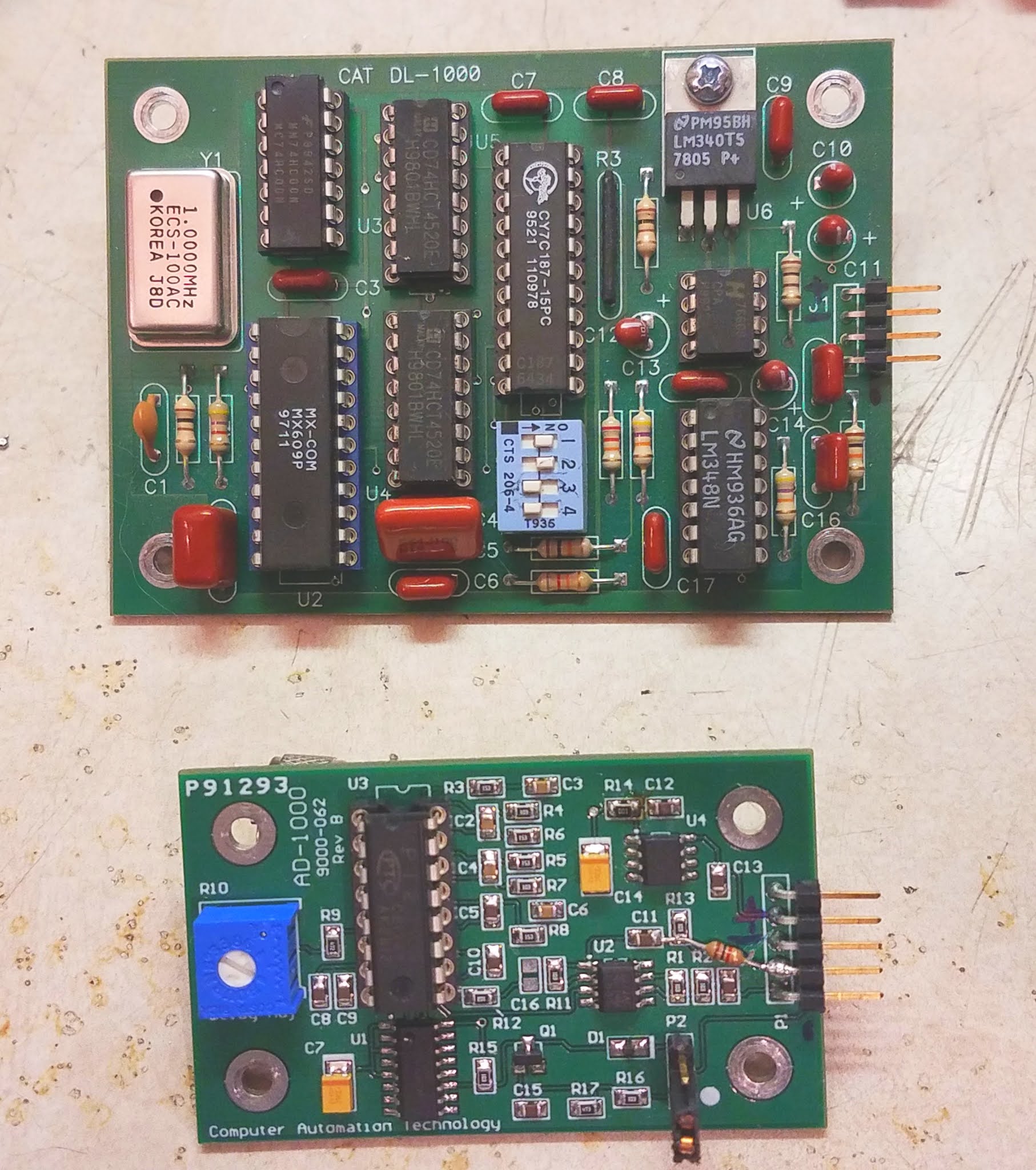
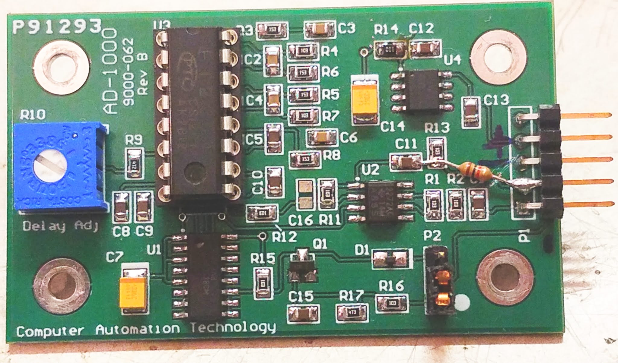
All of the repeater sites in question use CAT-1000 repeater controllers equipped with audio delay boards to help suppress the "squelch noise" and to ameliorate the delay resulting from the slow response of a subaudible tone decoder. Between the sites, I ran across the older DL-1000 and the newer AD-1000 - but all of these boards had "strange" issues.
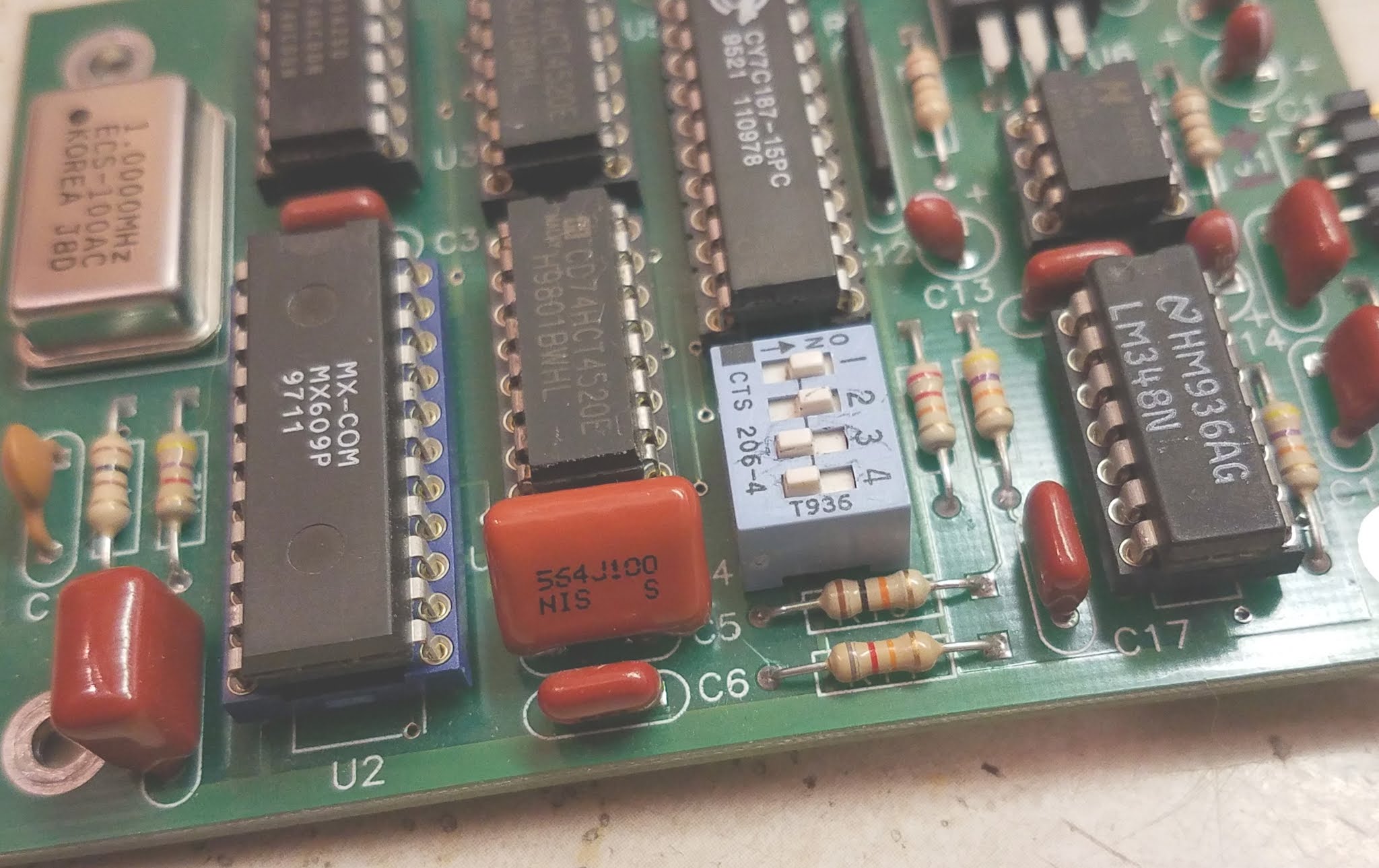
The DL-1000:
This board uses the MX609 CVSD codec chip which turns audio into a single-bit serial stream at 64 kbps using a 4-bit encoding algorithm, which is then fed into a CY7C187-15 64k x 1 bit RAM, the "old" audio data being read from the RAM and converted back to audio just before the "new" data is written.. To adjust the amount of delay in a binary-weighted fashion, a set of DIP switches are used to select how much of this RAM is used by enabling/disabling the higher-order address bits.
The problem:
It was noticed that the audio from the repeater had a bit of an odd background noise - almost a squeal, much like an amplifier stage that is on the verge of oscillation. For the most part, this odd audio property went unnoticed, but if an "A/B" comparison was done between the audio input and output - or if one inputted a full-quieting, unmodulated carrier and listened carefully on a radio to the output of the repeater, this strange distortion could be heard.
Figure 2: The location of C5 on the DL-1000. A 0.56 uF capacitor was used to replace the original 0.1 (I had more of those than I had 0.47's) and either one would probably have been fome As noted below, I added another to the bottom of the board. Click on the image for a larger version.
This issue was most apparent when a 1 kHz tone was modulated on a test carrier and strange mixing products could be heard in the form of a definite "warble" or "rumble" in the background, superimposed on the tone. Wielding an oscilloscope, it was apparent that there was a low-frequency "hitchhiker" on the sine wave coming out of the delay board that wasn't present on the input - probably the frequency of the low-level "squeal" mixing with the 1 kHz tone. Because of the late hour - and because we were standing in a cold building atop a mountain ridge - we didn't really have time to do a full diagnosis, so we simply pulled the board, bypassing the delay audio pins with a jumper.
On the workbench, using a signal tracer, I observed the strange "almost oscillation" on pin 10 of the MX609 - the audio input - but not on pin 7 of U7B, the op-amp driver. This implied that there was something amiss with the coupling capacitor - a 0.1uF plastic unit, C5, but because these capacitors almost never fail, particularly with low-level audio circuits, I suspected something fishy and checked the MX609's data sheet and noted that it said "The source impedance should be less than 100 ohms. Output channel noise levels will improve with an even lower impedance." What struck me was that with a coupling capacitor of just 0.1uF, this 100 ohm impedance recommendation would be violated at frequencies below 16 kHz - hardly adequate for voice frequencies!
Figure 3: The added 2.2uF tantalum capacitor on the bottom of the board across C5. The positive side goes toward the MX609, which is on the right. Click on the image for a larger version.
Initially, I bridged C5 with another 0.1uF plastic unit and the audible squealing almost completely disappeared. I then bridged C5 it with a 0.47uF capacitor which squashed the squealing sound and moved the 100 ohm point to around 4 kHz, so I replaced C5 with a 0.56uF capacitor - mainly because I had more of those than small 0.47uF units.
Not entirely satisfied, I bridged C5 with a 10uF electrolytic capacitor, moving the 100 ohm impedance point down to around 160 Hz - a frequency that is below the nominal frequency response of the audio channel - and it caused a minor, but obvious quieting of the remaining noise, particularly at very low audio frequencies (e.g. the "hiss" sounded distinctly "smoother".) Because I had plenty of them on-hand, I settled on a 2.2 uF tantalum capacitor (100 ohms at 723 Hz) - the positive side toward U2 and tacked to the bottom of side of the board - which gave a result audibly indistinguishable from 10 uF. In this location, a good-quality electrolytic of 6.3 volts or higher would probably work as well, but for small-signal applications like this a tantalum is an excellent choice, particularly in harsh temperature environments.
At this point I'll note that any added capacitance should NOT
be done with ceramic units. Typical ceramic capacitors in the 0.1uF
range or higher are of the "Z5U" type
or similar and their capacitance changes wildly with temperature meaning that
extremes may cause the added capacitance to effectively "go away" and
the squealing noise may return under those conditions. Incidentally, these types of ceramic capacitors can also be microphonic, but unless you have strapped your repeater controller to an engine, that's probably not important.
Were I to do this to another board I would simply tack a small tantalum (or electrolytic) capacitor - anything from 1 to 10 uF, rated for 6 volts or more - on the bottom side of the board, across the still-installed, original C5 (as depicted in Figure 3) with the positive side of the capacitor toward U2, the MX609.
Note:
One of the repeater sites also had a "DL-1000A" delay board - apparently a later revision of the DL-1000. A very slight amount of the "almost oscillation" was noted on the audio output of this delay board, too, but between its low level and having limited time on site, we didn't investigate further.
This board appears to be similar to the DL-1000 in that it has many of the same chips - including the CY7187 RAM, but it doesn't have a socketed MX609 on the top of the board, and likely a surface-mount codec on the bottom. It is unknown if this is a revision of the original DL-1000 or closer to the DL-1000C which has a TP4057 - a codec functionally similar to the MX609.
The question arises as to why this modification might be necessary? Clearly, the designers of this board didn't pay close enough attention to the data sheet of the MX609 codec otherwise they would have probably fitted C5 with a larger value - 0.47 or 1 uF would have probably been "good enough". I suspect that there are enough variations of the MX609 - and that the level of this instability - is low enough that it would largely go unnoticed by most, but to my critical ears it was quite apparent when an A/B comparison was done when the repeater was passing a full-quieting, unmodulated carrier and made very apparent when a 1 kHz tone was applied.
* * * * * * * * * * * * * * *
The AD-1000:
This is a newer variant of the delay board that includes audio gating and it uses a PT2399, a chip commonly used for audio echo/delay effects in guitars pedals and other musical instrument accessories as it has an integrated audio delay chip that includes 44 kbits of internal RAM.
The problems:
This delay board hadtwo problems: An obvious audio "squeal", very similar to that on the older DL-1000, but extremely audible, but there was a less obvious problem - something that sounded like "wow" and flutter of an old record on a broken turntable in that the pitch of the audio through the repeater would warble randomly. This problem wasn't immediately obvious on speech, but this pitch variation pretty much corrupted any DTMF signalling that one attempted to pass through the system, making the remote control of links and other repeater functions difficult.
RF Susceptibility:
Figure 4: The top of the modified AD-1000 board where the added 1k resistor is shown between C11/R13 and pin 2 of the connector, the board trace being severed. Near the upper-right is R14, replaced with a 10 ohm resistor, but simply jumpering this resistor with a blob of solder would likely have been fine. Click on the image for a larger version.
This board, too, was pulled from the site and put on the bench. There, the squealing problem did not occur - but this was not unexpected: The repeater site is in the near field of a fairly powerful FM broadcast and high-power public safety transmitters and it was noticed that the squealing changed based on wire dressing and by moving one's hand near the circuit board. This, of course, wasn't easy to recreate on the bench, so I decided to take a look at the board itself to see if there were obvious opportunities to improve the situation.
Tracing the audio input, it passes through C1, a decoupling capacitor, and then R2, a 10k resistor - and this type of series resistance generally provides pretty good resistance to RF ingress, mainly because a 10k resistor like this has several k-ohms of impedance - even at VHF frequencies, which is far higher impedance than any piece of ferrite material could provide!
The audio output was another story: R13, another 10k resistor, is across the output to discharge any DC that might be there, but the audio then goes through C11, directly to pin 1 of U2, the output of an op-amp. While this may be common practice under "normal" textbook circumstances, sending the audio out from an op-amp into a "hostile" environment must be done with care: The coupling capacitor will simply pass any stray RF - such as that from a transmitter - into the op amp's circuitry, where it can cause havoc by interfering/biasing various junctions and upsetting circuit balance. Additionally, having just a capacitor on the output of an op amp can be a hazard if there also happens to be an external RF decoupling capacitor - or simply a lot of stray capacitance (such as a long audio cable) as this can lead to amplifier instability - all issues that anyone who has ever designed with an op amp should know!
Figure 5: The added 1000pF cap on the audio gating lead. A surface-mount capacitor is shown, soldered to the ground plane on the bottom of the board, but a small disk- ceramic of between 470 and 1000 pF would likely be fine. Click on the image for a larger version.
An easy "fix" for this, shown in Figure 4, is simply to insert some resistance on the output lead, so I cut the board trace between the junction of C11/R13 and connector P1 and placed a 1k resistor between these two points: This will not only add about 1k of impedance at RF, but it will decouple the output of op amp U2 from any destabilizing capacitive loading that might be present elsewhere in the circuit. Because C11, the audio output coupling capacitor is just 0.1uF, the expected load impedance in the repeater controller is going to be quite high, so the extra 1k series resistance should be transparent.
Although not expected to be a problem, a 1000pF chip cap was also installed between the COS (audio gate) pin (pin 5) and ground - just in case RF was propagating into the audio path via this control line - this modification being depicted in Figure 5.
Of course, it will take another site visit to reinstall the board to determine if it is still being affected by the RF field and take any further action.
And no, the irony of a repeater's audio circuitry being adversely affected by RF is not lost on me!
The "wow" issue:
On the bench I recreated the "wow" problem by feeding a tone into the board, causing the pitch to "bend" briefly as the level was changed, indicating that the clock oscillator for the delay was unstable as the sample frequency was changing between the time the audio entered and exited the RAM in the delay chip. Consulting the data sheet for the PT2399 I noted that its operating voltage was nominally 5 volts, with a minimum of 4.5 volts - but the chip was being supplied with about 3.4 volts - and this changed slightly as the audio level changed. Doing a bit of reverse-engineering, I noted that U4, a 78L05, provided 5 volts to the unit, but the power for U2, the op amp and U3, the PT2399, was supplied via R14 - a 100 ohm series resistor: With a nominal current consumption of the PT2399 alone being around 15 milliamps, this explained the 1.6 volt drop.
The output at resistor R14 is bypassed with C14, a 33 uF tantalum capacitor, likely to provide a "clean" 5 volt supply to decouple U14's supply from the rest of the circuit - but 100 ohms is clearly too much for 15 mA of current! While testing, I bridged (shorted) R14 and the audio frequency shifting stopped with no obvious increase in background noise, so simply removing and shorting across R14 is likely to be an effective field repair, but because I had some on hand, I replaced R14 with a 10 ohm resistor as depicted in Figure 4 and the resulting voltage drop is only a bit more than 100 millivolts, but retaining a modicum of power supply decoupling and maintaining stability of the delay line.
Figure 6: Schematic of the AD-1000, drawn by inspection and with the aid of the PT2399 data sheet. Click on the image for a larger version.
Figure 6, above, is a schematic drawn by inspection of an AD-1000 board with parts values supplied by the manual for the AD-1000. As for a circuit description, the implementation of the PT2399 delay chip is straight from the data sheet, adding a dual op-amp (U2) for both input and output audio buffering and U1, a 4053 MUX, along with Q1 and components, were added to implement an audio gate triggered by the COS line.
As can be seen, all active circuits - the op-amp, the mux chip and delay line - are powered via R14 and suffer the aforementioned voltage drop, explaining why the the supply voltage to U3 varied with audio content, causing instability in audio frequencies and difficulty in decoding DTMF tones passed through this board - and why, if you have one of these boards, you should make the recommended change to R14!
Conclusion:
What
about the "wow" issue? I'm really surprised that the value of R14 was
chosen so badly. Giving the designers the benefit of the doubt, I'll
ignore the
possibility of inattention and chalk this mistake, instead, to
accidentally using a 100 ohm resistor instead of a 10 ohms resistor -
something that might have happened at the board assembly house rather
than being part of the original design.
After a bit of digging around online I found the manual for the AD-1000 (found here) which includes a parts list (but not a schematic) that shows a value of 100 ohms for R14, so no, the original designers got it wrong from the beginning!
While the RF susceptibility issue will have to wait until another trip to the site to determine if more mitigation (e.g. addition of ferrite beads on the leads, additional bypass capacitance, etc.) is required, the other major problems - the audio instability on the DL-1000 and the "wow" issue on the AD-1000 have been solved.
* * * * * * * * * * * * * * *
Comments about delay boards in general:
Audio delay/effects boards using the PT2399 are common on EvilBay, so it would be trivial to retrofit an existing CAT controller with one of these inexpensive "audio effects" boards to add/replace a delay board - the only changes being a means of mechanically mounting the new board and, possibly, the need to regulate the controller's 12 volt supply down to whatever voltage the "new" board might require. The AD-1000 has, unlike its predecessor, an audio mute pin which, if needed at all, could be accommodated by simple external circuitry. Another blog post about using one of these audio delay/effects boards for repeater use will follow.
In bench testing, the PT2399 delay board is very quiet compared the MX609 delay board - the former having a rated signal-noise ratio of around 90 dB (I could easily believe 70+ dB after listening) while the latter, being based on a lossy, single-bit codec, has a signal-noise ratio of around 45 dB - about the same as you'd get with a PCM audio signal path where 8 bit A/D and D/A converters were being used.
A signal/noise ratio of around 45 dB is on par with a "full quieting" signal on a typical narrowband FM communications radio link so the lower S/N ratio of the MX609 as compared with the PT2399 would likely go unnoticed. Were I to implement a repeater system with these delay boards I would preferentially locate the MX609-based delay boards in locations where the noise contribution would be minimized (e.g. the input of the local repeater) while placing the quieter PT2399-based board in signal paths - such as a linked system - where one might end up with multiple, cascaded delay lines on link radios as the audio propagates through the system. Practically speaking, it's likely that only the person with a combination of a critical ear and OCD is likely to even notice the difference!