via Hackaday: Blowing Up Shell Scripts
 One of the most universal experiences of any Linux or Unix user is working through...
  One of the most universal experiences of any Linux or Unix user is working through...
  Although Android technically runs on top of Linux, generally most Android devices abstract away the...
 Ever since I built my RaspberryPi/SHARI AllStarLink node I’ve had to manage connecting/disconnecting to/from other nodes using the Allmon2 or Supermon web admin interfaces. These work fairly well albeit, a bit clunky and buggy. It’s impossible to use from a mobile device though and so I have to get my Macbook out each time I want to connect/disconnect nodes.
Being a Node-RED fanatic I decided that I should put something together that was more portable, mobile friendly and much easier to use. A simple user interface is all that is required and can be achieved very easily using the standard Node-RED dashboard nodes.
Initially I started investigating the Linux command-line interface for Asterisk, the VOIP system that underpins AllStarLink (ASL). I very quickly discovered that the ASL node can be very easily controlled directly from the command-line and that this would be an ideal interface to use to enable node management via a Node-RED dashboard.
In very little time at all I had an experimental control dashboard working with the ASL node and was able to connect/disconnect to/from a single node. All that was required now was to extend this so that I could connect to a number of nodes with nothing more than a push of a button.
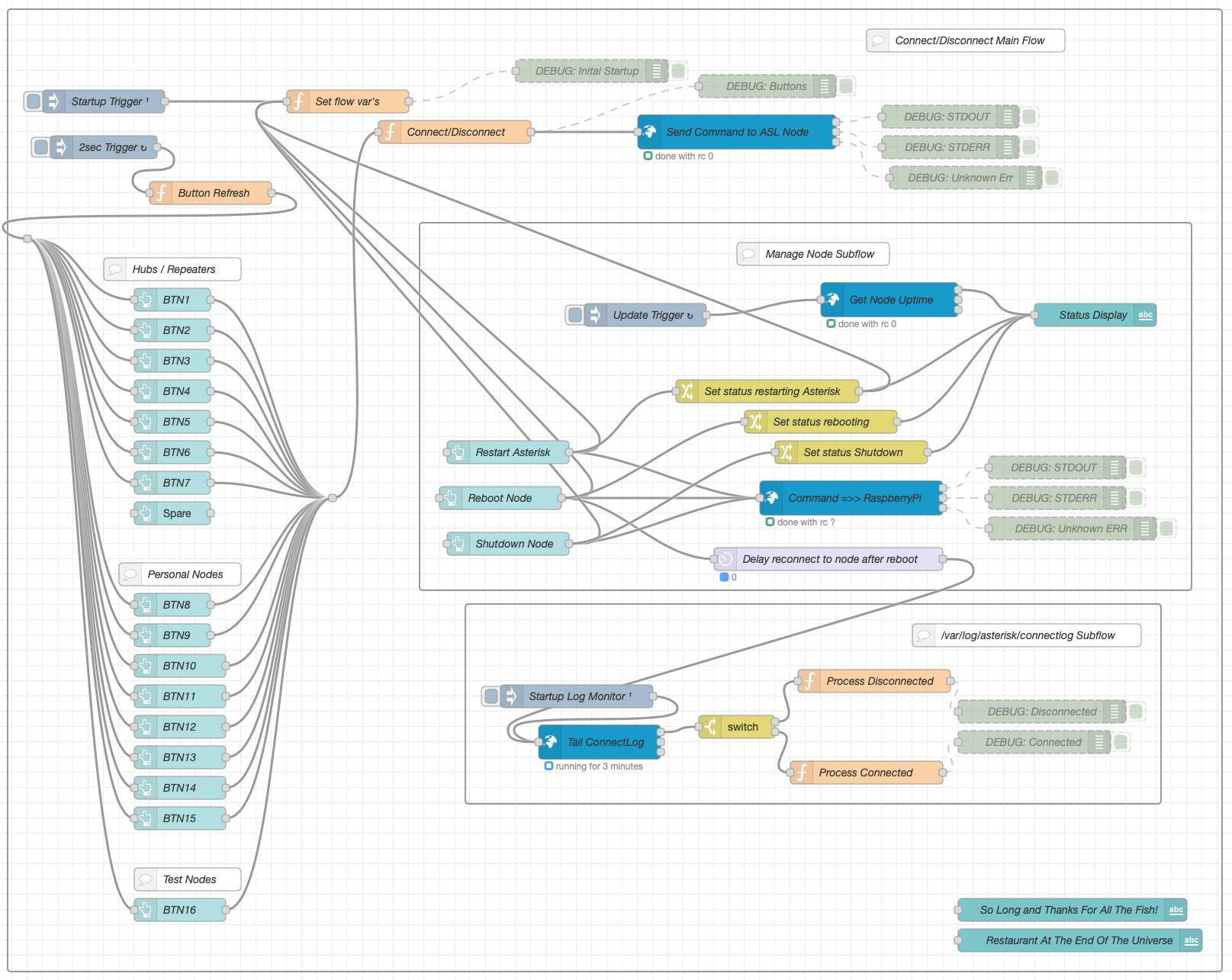
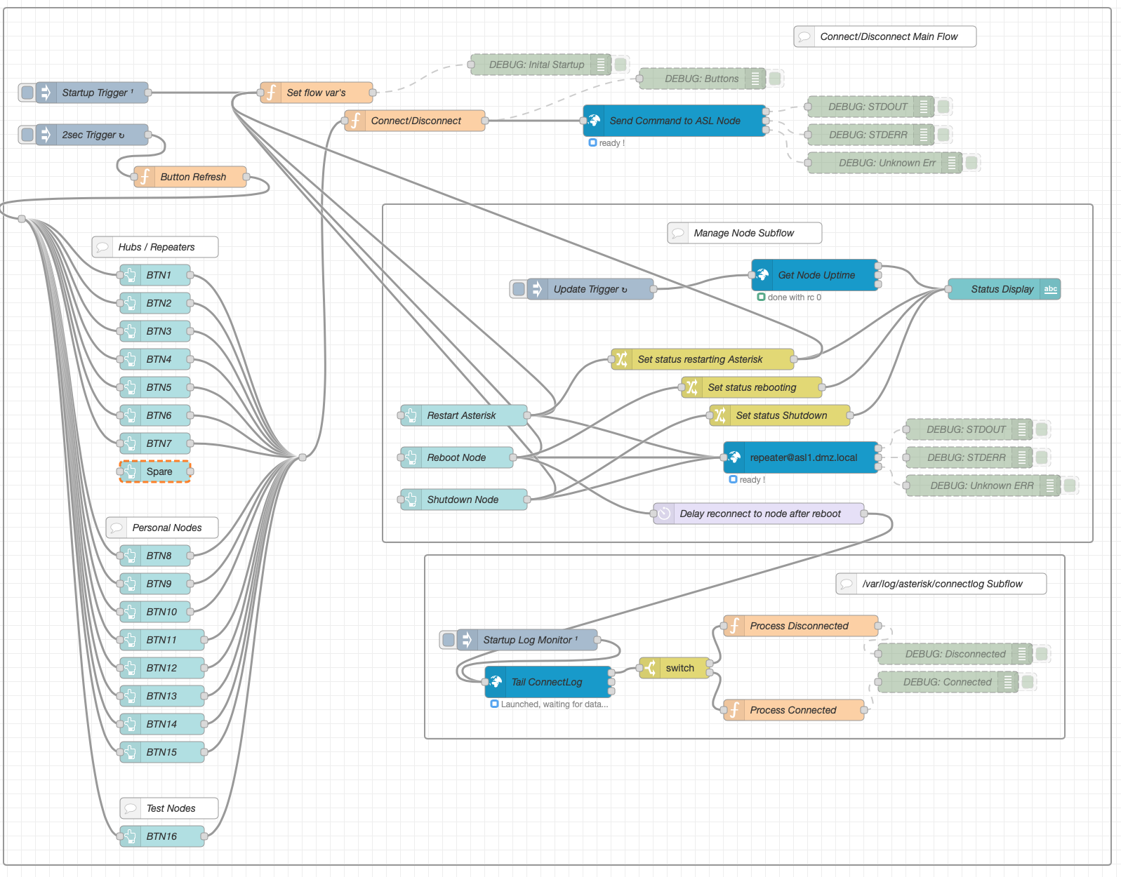
The resultant flow consists of 3 sections, Connect/Disconnect Main Flow, Manage Node Subflow and /var/log/asterisk/connectlog Subflow.
The Connect/Disconnect Main Flow handles all the input from the buttons on the dashboard and the communication to the underlying Asterisk VOIP system.
The button status is denoted by 3 colours, green (Ready to connect), orange (Transitioning to/from connect) and red (Connected). Each button is updated automatically by the button refresh function that is triggered every 2 seconds.
The Manage Node Subflow provides a simple interface to restart the Asterisk VOIP system, reboot the RaspberryPi and shutdown the RaspberryPi. The node status is automatically updated every 45 seconds and will show when the Asterisk subsystem is being restarted or the node is being rebooted or shutdown.
Finally the var/log/asterisk/connectlog Subflow monitors the Asterisk connectlog looking for connect/disconnect messages so that it can signal to update each button status.
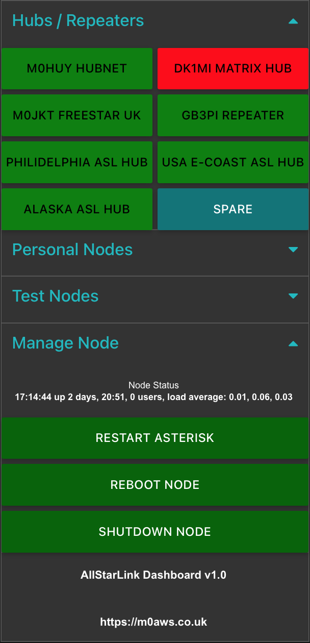
Each section of the dashboard can be collapsed/opened by touching/clicking the little blue arrows on the right of the dashboard. The dashboard works fine on Android, iOS, Windows, MacOS and Linux.
If you’re not familiar with Node-RED and haven’t yet installed it to your PC, take a look at the Node-RED Getting Started Page. The information takes you through installing Node-RED onto a multitude of devices including PC and RaspberryPi devices.
Once you have Node-RED installed all you need to do is download the AllStarLink Control Dashboard Flow and import it to your Node-RED flow editor.
Once downloaded, select Import from the burger menu icon on the right-hand side of the flow editor as shown below and import the flow file.
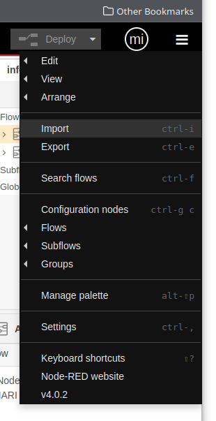
Once imported you will find that some of the nodes in the flow are not available. This is because you need to add them to the flow editor palette before being able to deploy the flow.
Drop down the same menu as shown above but, this time select Manage Palette. This will open another window where you will need to select the Install tab as shown below.
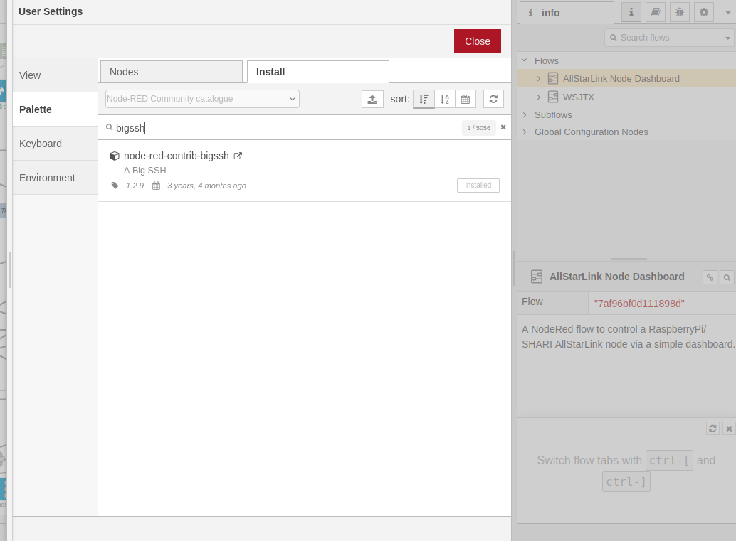
You need to install two node sets to complete the flow, node-red-contrib-bigssh and node-red-dashboard. Type in the name of each package one at a time in the search bar and then click the Install button.
Once the two packages are installed you then need to configure the credentials for logging into your RaspberryPi. This is simply done by double clicking the blue Send Command to ASL node at the top of the main flow and then clicking the Pencil button at the end of the Credentials field. This will open another window where you will need to type in the IP Address of your ASL RaspberryPi into the Host field, then enter 22 into the port field, add repeater into the Username field (repeater is the default username, if you have changed this then you will need to add the new username name in instead) and then the password associated with the repeater login into the Password field. (Normally allstarlink)
Once this is done, do the same on the other blue nodes, namely “Get Node Uptime“, “Command =>> RaspberryPi” and “Tail ConnectLog”.
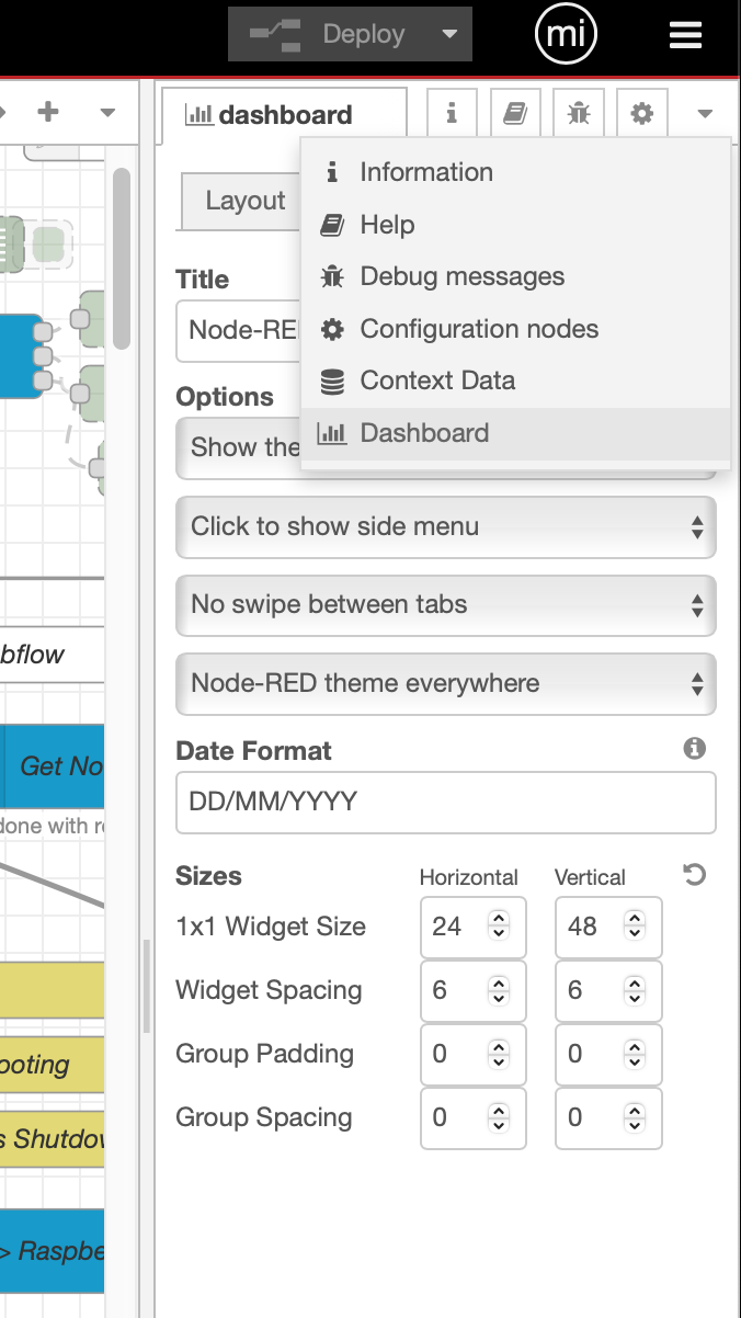
The final thing to setup is the dashboard size. Click on the downward pointing triangle at the top right of the menu bar (under the burger menu) and select dashboard. Check that the sizes are set the same as in the image below. For some reason, these settings aren’t always imported (Possible bug?) so, if your dashboard layout isn’t like shown above it will be because these settings failed to import.
You are now ready to deploy your AllStarLink Control Dashboard!
Press the red Deploy button at the top of the flow editor window.
To access the dashboard from any device, open your favourite web browser and enter the following URL: http://IP-Address-of-Node-RED-Computer:1880/ui
Finally, if you want to change the nodes that each button connects/disconnects you will need to edit the set flow var’s function at the top of the main flow. All you will need to do is replace the existing node numbers taking care not to alter the rest of the code in any way otherwise, it could stop the flow from working.
Once you’ve edited the node numbers, double click on the associated button node and change its Label to show the new node name.
Once your changes are complete, Deploy the flow again and your changes will be live.
This is version 1 of the ASL Dashboard, I already have ideas for version 2 that will also have the ability to enter a node number into a field and connect to it without the need to program it into a button.
More soon …
Ever since we moved into the village of Eyke we’ve suffered with power cuts and power surges. It’s been that bad that we have a number of uninterruptible power supplies (UPS) dotted around the house to keep important things running when the power goes out.
Of late it’s been getting worse, not just the power cuts but, the power bouncing on and off very quickly for period of 10-15secs when the power comes back on. Unfortunately we had a particularly bad power bounce when the power came back on and it killed the main UPS for the IT equipment rack and also took out my RAID storage array that I use for backups.
On top of this the main server computer also took a hit and its solid state (SSD) drives started to fail. This left me in a position where I had no backups to recover from and had to get all the data off the running virtual machines (VMs) before the SSDs failed.
My old server that I decommissioned some months ago was now my radio shack PC and so had a desktop operating system on it and lots of HAM radio software installed and configured but, I needed to press it back into service as a server again, very quickly!
So after backing up the desktop data I rebuilt the computer as a server again and began the tedious job of building new VMs and migrating the configuration and data over from the old VMs.
You’re probably wondering why I didn’t just transfer the VMs over hole to the replacement server?
To do this I’d need to shut them down to get a clean snapshot however, when I tried it with a small, unimportant VM it became corrupt during the shutdown process and could no longer be transferred to the replacement server.
Not wanting to take the risk with any of the other VMs due to having lost all the backups, I decided to replicate all the VMs manually. Needless to say this isn’t a 5min job!
So, after a rather long week rebuilding everything I now have all the services up and running on the replacement server and the damaged server ready to be stripped down to an empty case and rebuilt from scratch.
This has meant that at times my M0AWS Blog, The Matrix server and other online services have been offline for short periods but, sadly there was nothing I could do about it. Unfortunately the national grid/power companies take no responsibility for such events and say they only guarantee the frequency of the mains power (50Hz) not the voltage!
The last entry in the old UPS log was an over voltage alert showing 1000v!
With a new UPS in place and online, we’ve already had a number of power cuts and it’s handled them well, lets hope we don’t get another big one!
Backups are now running again on external drives that are disconnected when not in use to protect them from power surges and all the services successfully migrated over to the replacement server.
More soon ….
Coding of version 1 of the AllStarLink Dashboard is now complete and in the final testing phase. Below is a short video clip showing some of the functionality.
The Node-RED flow for the web app is pretty compact and easy to alter should I add more functionality in the future.
The dashboard is designed such that it’ll display nicely on mobile phones, tablets and desktop computers so, I can easily control my AllStarLink SHARI node from any of my devices around the house.
I’ll put together a more detailed article on the web app once testing is complete and it’s ready to be released into the wild.
More soon …
This is more of an aide memoire for myself more than anything but, may be useful to anyone who is using a SHARI powered AllStarLink node.
Out the box the SHARI build as documented here and here uses node numbers in announcements when connecting/disconnecting. The information in this article will change this so that the announcements use the node callsigns instead of node numbers.
As user repeater, login to the RaspberryPi that the SHARI is connected too via SSH and run the following commands:
1: Edit /usr/sbin/write-node-callsigns and change SRCDIR to point to /var/www/html/allmon2
# 28/08/24 - M0AWS - Changed path to point to allmon2
##SRCDIR=/var/www/html/allmon
SRCDIR=/var/www/html/allmon2
2: Copy the astb.txt file into the necessary directory:
sudo cp /var/hdd.log/asterisk/astdb.txt /var/www/html/allmon23: Run the programme to create the sound files. (This will run for some time on a RaspberryPi 3b)
sudo /usr/sbin/write-node-callsigns4: Once all the sounds files have been created, connect to another node and you should now get node name announcements instead of node numbers ….
More soon …
 Read more at ARRL.org
 After writing my article on how to build an AllStarLink node using a RaspberryPi 3b and SHARI radio device I was asked by a few people if I could possibly automate the process to make it easier for those who aren’t Linux command line junkies like me.
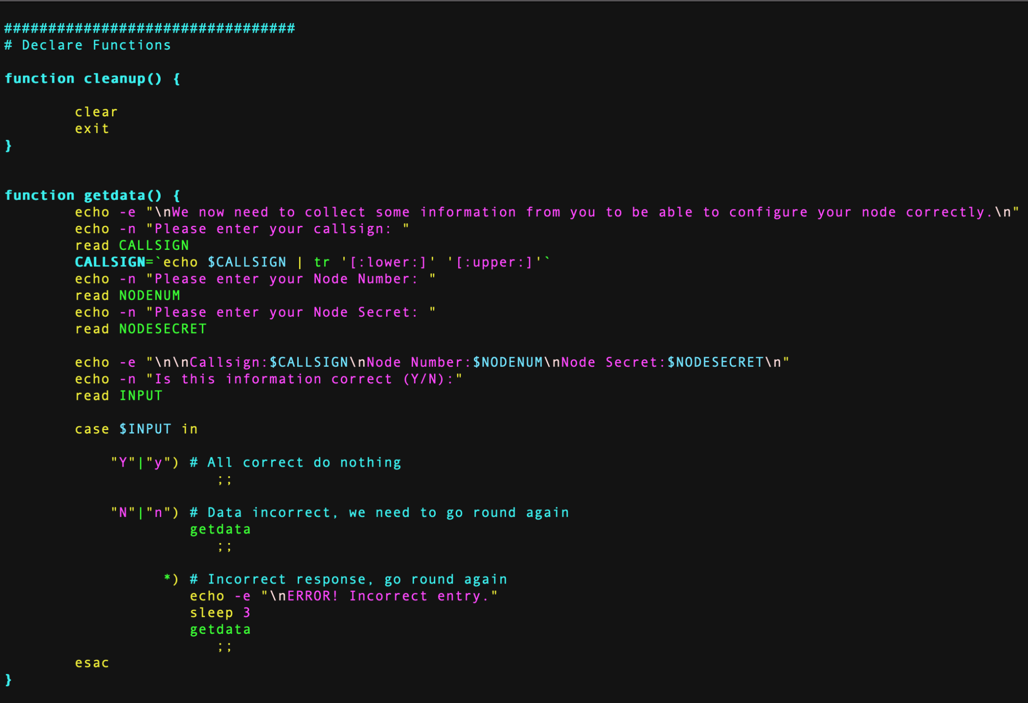
Over the last couple of days in-between doing other things I’ve been writing and testing a BASH shell script that will completely configure a fully working AllStarLink node.
To use the script you must already have your RaspberryPi (preferably a Pi 3b) connected to your LAN with full internet access using the Raspbian based version of the AllStarLink software downloadable from here.
The specific version I use is:
asl-2.0.0-beta.6-kc1kcc-20210324-rpi-armhfI have tested the BASH script using this specific version of O/S only.
Once your RaspberryPi 3b is up and running, has full internet access and is accessible on your local LAN, using SSH login in as the user ‘repeater‘ using the password ‘allstarlink‘.
It’s important you only use this login to configure the node as this is the user the script is expecting to be run by. You must login via SSH as the SHARI device needs to be connected to the RaspberryPi 3b and you won’t be able to connect a keyboard and mouse at the same time. (If you are using two USB cables for the SHARI device then you can use a keyboard and mouse along with a monitor attached to your RaspberryPi instead of using SSH).
Once logged in as user repeater run the following wget command to download the zipped install script:
wget https://m0aws.co.uk/AllStarLink/AllStarLinkBuild.zipOnce downloaded you need to unzip the program from the zip file and make it executable using the following commands:
unzip ./AllStarLinkBuild.zip
chmod 755 ./install.sh
You are now ready to build your AllStarLink node. Before you run the script make sure you have your node number and node secret to hand. These are obtained from the AllStarLink portal.
Once you’ve got all your node information you can run the script using the following command:
./install.shThe script will now take you through the full process of updating the operating system as necessary, installing all the required packages and software. It will then reboot the RaspberryPi and you will need to login and run the script a second time using the command above.
On the second run the script will install some python specific software, ask you to enter your callsign, node number and node secret and will then configure your node. The last thing it does is configure the Allmon2 and Supermon Web Admin websites. During this process it will ask you to enter a password twice for the Admin user for the two websites, make sure you make a note of this password as you will need it to login and control your node.
Once the node is configured it will be rebooted and you will then be able to connect to your node using your favourite web browser and the user admin and the password you set above.
To access the Allmon2 web-admin system use the following URL:
http://your-RaspberryPi-IP-Address/allmon2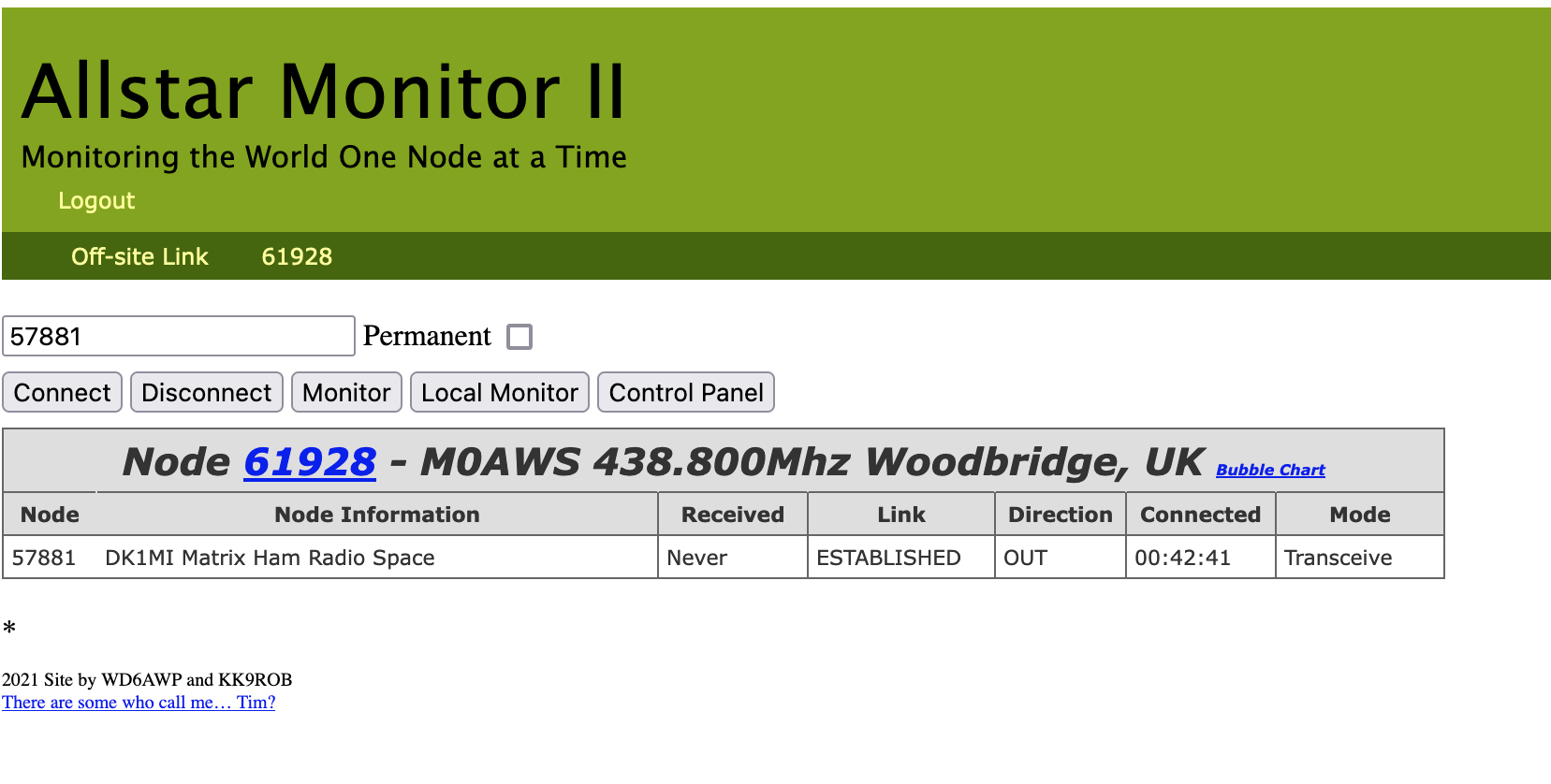
For those of you who prefer Supermon you an use the following URL:
http://your-RaspberryPi-IP-Address/supermon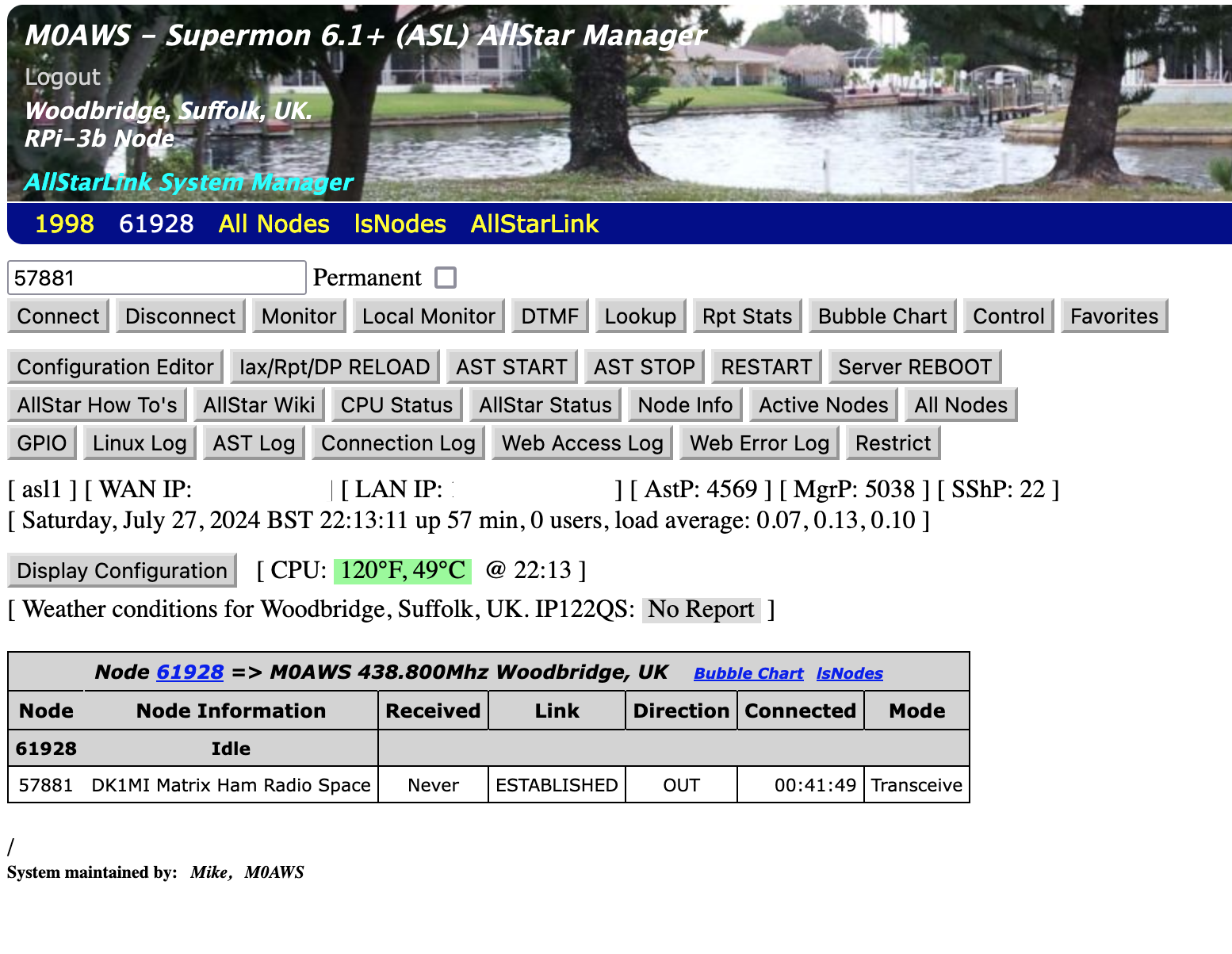
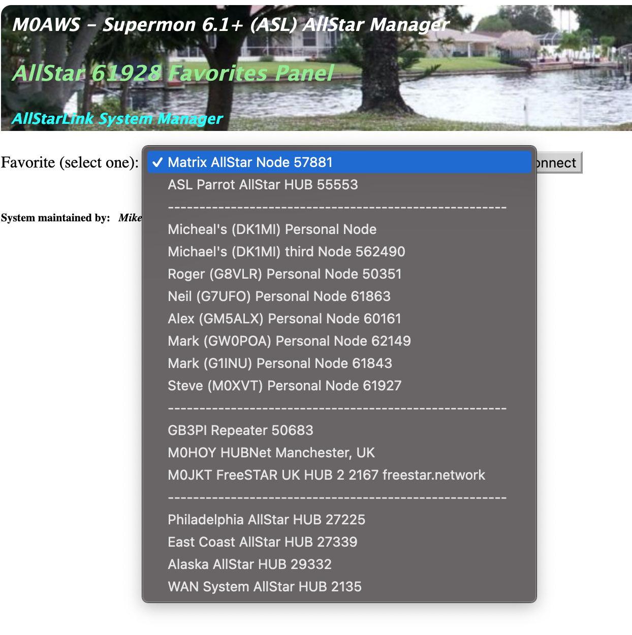
I have also pre-populated the Favorites button with a list of nodes that I use often. You can easily change these entries by editing the favorites.ini file in the /var/www/html/supermon directory as user root.
When you first login to your node via your web browser you’ll notice that it says your node isn’t in the database. You can update the database by using the following URL in your web browser:
http://your-RaspberryPi-IP-Address/allmon2/astdb.phpThis will force an update of the database and your node information should now be displayed correctly.
Hopefully this will make it much easier for the non Linux people to build an AllStarLink node using a RaspberryPi 3b and a SHARI radio device.
More soon …
Meshtastic devices have really taken off in the UK over the last few months and there is now an established Mesh across a large portion of the UK mainland.
Looking to expand the device capability I stumbled across a really interesting little project that is still in the early stages of development but, is functional and worth trying out.
The TC²-BBS Meshtastic Version is a simple BBS system that runs on a RaspberryPi, Linux PC or virtual machine (VM) and can connect to a Meshtastic device via either serial, USB or TCP/IP. Having my M0AWS-1 Meshtastic node at home connected to Wifi I decided to use a TCP/IP connection to the device from a Linux VM running the Python based TC²-BBS Meshtastic BBS.
Following the instructions on how to deploy the BBS is pretty straight forward and it was up and running in no time at all. With a little editing of the code I soon had the Python based BBS software M0AWS branded and connected to my Meshtastic node-1.
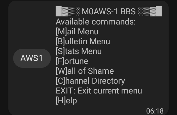
The BBS system is very reminiscent of the old packet BBS systems of a bygone era but, it is ideal for the Meshtastic world as the simple menus and user interface are easily transmitted in seconds via the Mesh using minimal bandwidth.
The BBS is accessible by opening a Direct Message session with the M0AWS-1 node. Sending the letter H to the node will get you the initial help screen showing the menu above and then from there onwards it’s just a matter of selecting the menu item and following the BBS prompts to use the BBS.
The BBS also works across MQTT. I tested it with Dave, G4PPN and it worked perfectly via the Meshtastic MQTT server.
This simple but, effective BBS for the Meshtastic network will add a new message store/forward capability to the Mesh and could prove to be very important to the development of the Meshtastic mesh in the UK and the rest of the world.
More soon …
We’ve recently added a new room to the Matrix HAM Radio Space for Digital Voice modes as this was an area of interest that didn’t really fit into any of the other rooms.
The new Digital Voice room has attracted a lot of attention from members, with a lot of the focus being on the AllStarLink system. Michael, DK1MI built an AllStarLink node in the cloud for us all to use for Matrix Nets and so I decided I had to get in on the fun.
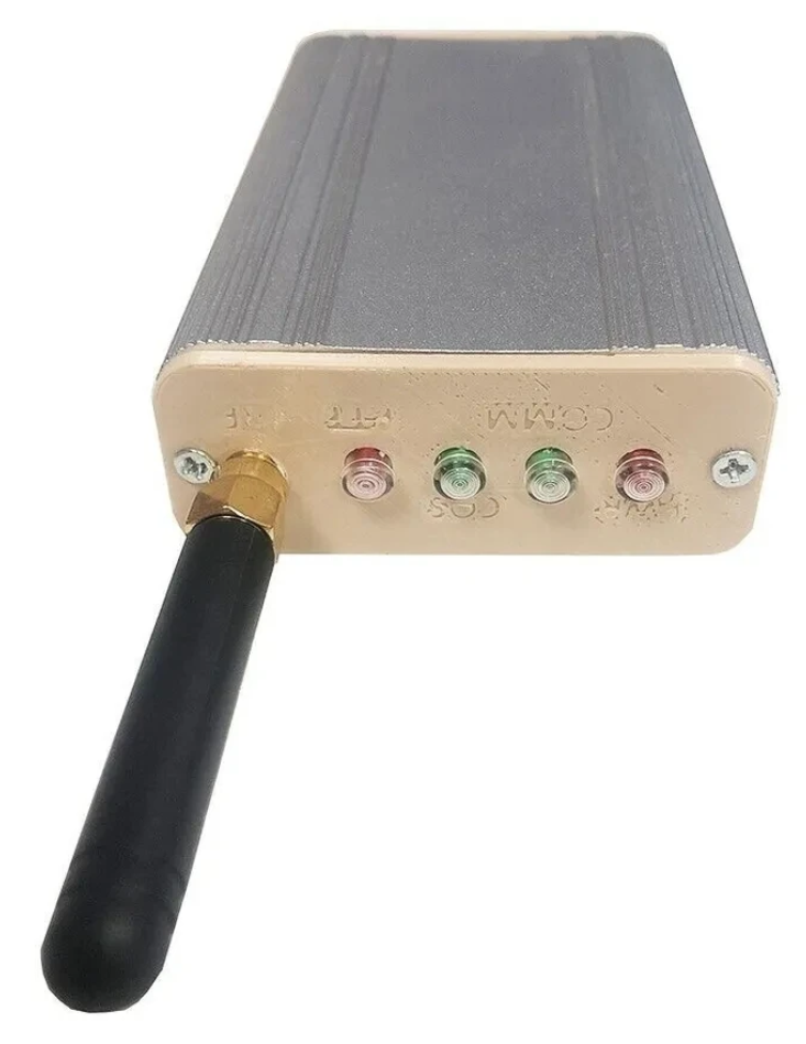
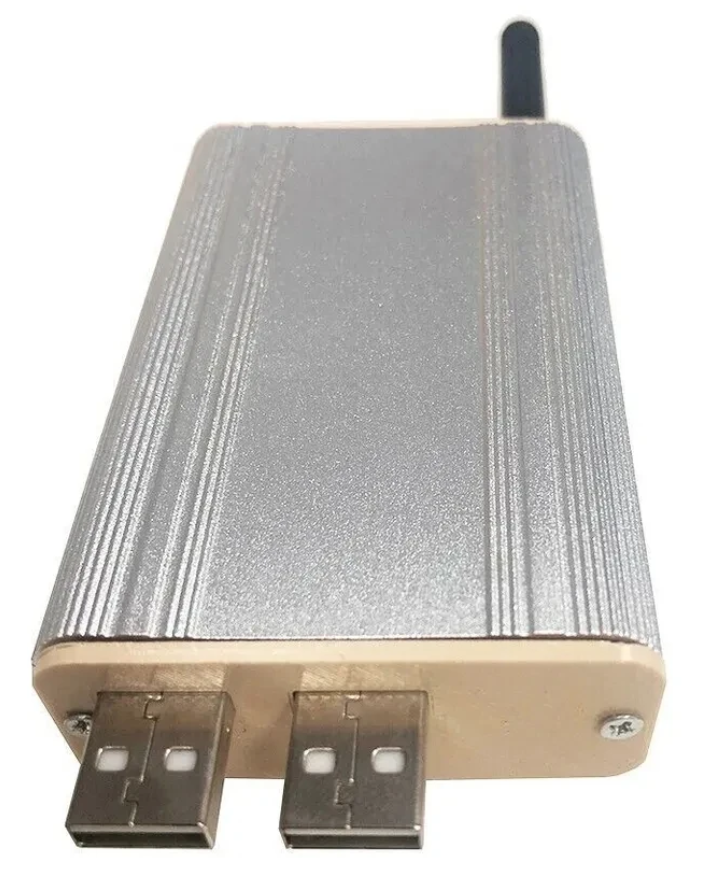
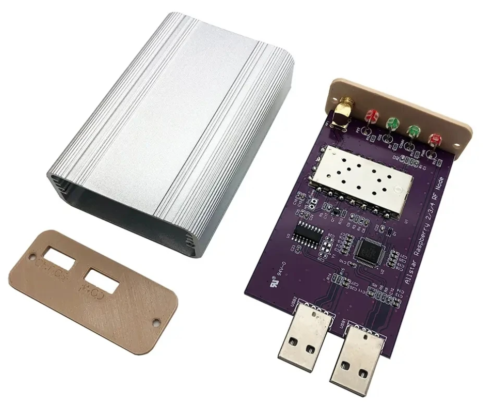
The Jumbospot SHARI SA818 Amateur Radio AllStarLink Radio Interface was originally designed by N8AR and implements a RaspberryPi 2/3/4 hosted AllStarLink node using a NiceRF SA818 embedded VHF/UHF radio module and sound card.
The two USB connectors on the SHARI device are position such that they plug into two of the available 4 USB ports on the RaspberryPi without the need for cables. This keeps the whole solution together in one neat package.
Before you start you will need to obtain a node number and secret (password) from the AllStarLink Portal. To get this you will need to provide proof to the AllStarLink administrators that you are a licensed Amateur Radio (HAM) operator. This is done by uploading a copy of the first page of your HAM licence to the website for the admin team to check. This can take 24hrs to be completed so make sure you get this all done before trying to build your node. You cannot build a node successfully without a node number and secret.
Of course you will also need a transceiver that can operate on the 438.800Mhz frequency or other frequency of your choice on the 2m or 70cm HAM band.
You will also need to open port 4569 on your internet router and setup port forwarding to the IP Address that you will be using on your RaspberryPi node. It’s important to use a static IP Address on your RaspberryPi.
There are quite a few different Linux based operating system (O/S) images that are available for the RaspberryPi devices that have been specifically tailored for the AllStarLink node and include all the necessary software and library packages out the box.
I decided to use the Raspbian GNU/Linux 10 (buster) based distribution as it is based on the very stable and reliable Debian Linux distro. You can download the exact version I am using from the Raspbian link above or directly from my website here.
Once downloaded you need to burn the ISO image onto a suitable SD card for your RaspberryPi. I use BalenaEtcher as it’s extremely quick and reliable at burning ISO images to SD cards.
Of course if you are a hardline Linux command line junkie you can always use dd to create the SD card.
Once you’ve got your O/S onto your SD card, slot it into your RaspberryPi making sure your SHARI device is connected to the two USB ports and then power it up. Make sure you have a good PSU for the RaspberryPi as the two devices together draw around 3A of current during the transmit cycle. (I use a 3.6A PSU from Amazon).
The default login for the Raspbian O/S is shown below. Login via SSH and configure your RaspberryPi for your local network. It’s important to use a static IP Address configured either directly on the RaspberryPi or via DHCP in your router.
Login: repeater
Passsword: allstarlink
SSH port: 22
Once you have your RaspberryPi connected to your LAN you are ready to start configuring it for AllStarLink.
The first thing you need to do is login to the raspi via SSH and then become root user using sudo as shown below:
sudo su -Once you are root user, you need to add the AllStarLink repo to the sources file and update the operating system using the following command:
curl -s http://apt.allstarlink.org/repos/repo_signing.key | apt-key add
apt update --allow-releaseinfo-change
apt dist-upgrade
Copy and paste each line one at a time into your terminal. Once the last command finishes, the system is up to date and can be rebooted as follows:
rebootOnce the raspi has rebooted, login again via SSH as user repeater and then become root user again.
You now need to install a couple of Python components that are required by the system to function. Use the commands below as user root:
apt-get install python3-dev python3-pip
pip3 install pyserial
Next you need to change directory into the asterisk config file directory using the command shown below:
cd /etc/asteriskIn this directory you will find all the default config files that come as part of the distro. For this build we’re not going to use them and so we need to move them out of the way ready for a set of config files that have already been configured correctly.
Using the following commands create a new directory, move into that new directory and then move all the unwanted configuration files into it:
mkdir ORIGINAL-CONF-FILES
cd ./ORIGINAL-CONF-FILES
mv ../*.conf ./
ls -la
cd ../
You should now be back in the /etc/asterisk directory which will now be empty apart from the custom directory which we left in place.
You now need to copy the correctly configured configuration files into the /etc/asterisk directory. Start by downloading the zip file containing the new configuration files
Once downloaded, copy the .zip file into the repeater users home directory (/home/repeater) using either scp on the Linux command line or if using Windows you can use the FileZilla Client in SFTP mode using the login details above.
Once you have the .zip file in the repeater user’s home directory you need to copy the file into the /etc/asterisk directory as user root:
cp /home/repeater/AllStarLink-Config-v3.zip /etc/asterisk/Next as user root, change directory into the /etc/asterisk directory and unzip the .zip file:
cd /etc/asterisk
unzip ./AllStarLink-Config-v3.zip
Once the file is unzipped you will have a directory called AllStarLink-Config in the /etc/asterisk directory. You now need to cd into the directory, copy all the files out of it into the /etc/asterisk directory leaving a copy in the AllStarLink-Config directory for future reference:
cd /etc/asterisk/AllStarLink-Config
cp ./* /etc/asterisk
cd /etc/asterisk
You now need to move a couple of files into the repeater users home directory using the following commands:
mv ./SA818-running.py /home/repeater
mv ./gpio /home/repeater
Once the files have been moved you need to set the correct ownership and privileges on the files using the following commands:
chown -R root:root /etc/asterisk/*.conf
chown repeater:repeater /home/repeater/gpio
chown repeater:repeater /home/repeater/SA818-running.py
chmod 755 /home/repeater/gpio
chmod 755 /home/repeater/SA818-running.py
The gpio BASH script and configuration details were supplied by Mark, G1INU in the Digital Voice room on the Matrix. It adds the COS light functionality to the setup. The COS light will now light every time the SA818 hears RF on the input.
The next thing you need to do is configure the SA818 radio device in the SHARI. The script I used was originally from https://wiki.fm-funknetz.de/doku.php?id=fm-funknetz:technik:shari-sa818 all I’ve done is change the entries to switch off CTCSS and change the frequency to 438.800Mhz. Configuring the SA818 is done by running the SA818-running.py Python programme that you moved into the repeater user home directory. Making sure you are still user root, run the following commands:
cd /home/repeater
./SA818-running.py
At this point your SHARI SA818 device will be configured to operate on 438.800Mhz and CTCSS will be disabled.
If you want to change the frequency or enable and set a CTCSS tone to access the node you will need to edit the Python programme using your favourite text editor and change the entries accordingly. Once changed rerun the program as shown above and your SHARI will be reconfigured to your new settings.
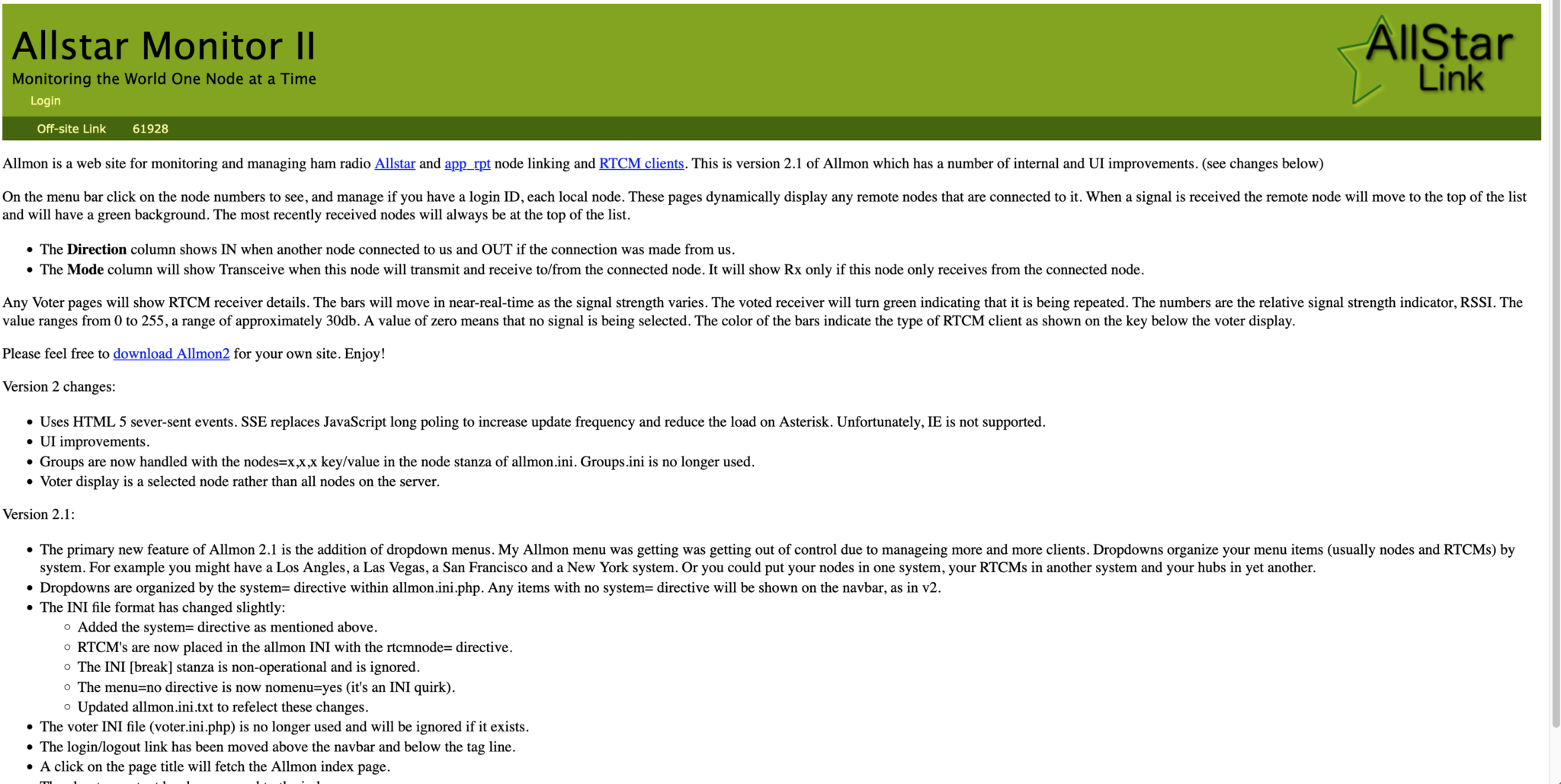
Next you need to move the allmon.ini.php file into the correct directory so that it enables access to the Allstar Monitor web page on the device so that you can manage connecting/disconnecting nodes. Use the following commands as user root to achieve this:
cd /etc/asterisk
mv ./allmon.ini.php /var/www/html/allmon2/
chown root:root /var/www/html/allmon2/allmon.ini.php
chmod 644 /var/www/html/allmon2/allmon.ini.php
The allmon.ini.php file needs to have your node name entered into it to work correctly. As user root, change directory and edit the file using your favourite editor.
cd /var/www/html/allmon2Using your text editor, search for the line starting [XXXXX] and change the XXXXX to your node number. Save the change and exit the file.
At this point you are almost complete, all that is left to do is add your node number and node secret into the appropriate configuration files in the /etc/asterisk directory.
Since I am a Linux command line junkie I use vi to edit all the configuration files on the command line as user root, but you can use any editor of your choice.
cd /etc/asteriskStart with the extensions.conf file. Search for the line starting with NODE = and delete the XXXXX entry and insert your node number. Save the file and exit it.
Next you need to edit the iax.conf file. This time search for the line starting with
register= and change the XXXXX for your node number and the YYYYYYYYYYYY for your node secret. Be careful not to accidentally delete any other characters in the lines otherwise it will corrupt the configuration file.
In the same file search for the two lines that start with secret = and change the YYYYYYYYYYYY for your node secret. Once you have changed both of the secret entries, save and exit the file.
The final file to edit is the rpt.conf file. Once again open the file using your favourite editor and search for the line starting with XXXXX = radio@127.0.0.1:4569/XXXXX, change the XXXXX entries for your node number making sure not to delete any other characters next to the XXXXX entries.
Further down in the same file there is a line that starts with [XXXXX], once again change the XXXXX for your node number making sure to keep the square brackets at each end of the node number as you edit it.
Finally move down to the very bottom of the file and find the two lines that start with /home/repeater/gpio, once again change the XXXXX entries for your node number.
The final thing to change in the rpt.conf file is to replace my callsign with your own callsign so that the node identifies itself correctly. Scroll through the file until you find the two lines shown below, delete M0AWS and add your own callsign instead making sure you keep all the spaces between words as shown below.
idrecording = |i DE M0AWS
idtalkover = |i DE M0AWS
Once this is done, save and exit the file. At this point your node should be fully configured and will only require a reboot to get it working.
As user root, reboot your raspi using the reboot command.
rebootOnce your raspi comes back online, login using SSH as user repeater and then become root user using the sudo command detailed above.
You now need to create the admin user password for the Allstar Monitor web page on the device. This is done using the following commands as user root:
cd /var/www/html/allmon2
htpasswd -c .htpasswd admin
You will be asked to enter a password twice for the admin user. Make sure you make a note of this user/password as you will need it to login to the web page.
Finally check that the controlpanel.ini.php file is in the /var/www/html/allmon2 directory:
ls -la /var/www/html/allmon2/controlpanel.ini.phpIf the file isn’t shown in the directory, enter the following commands to create the file in the correct place as user root and then exit the SSH session:
cd /var/www/html/allmon2
cp ./controlpanel.ini.txt ./controlpanel.ini.php
cd
exit
Once this is done your configuration is complete, logout from the terminal session by entering exit once more and your SSH session will terminate.
Using your favourite web browser enter the IP Address of your raspi into the URL bar as shown below:
http://<Your-Raspi-IP>/allmon2Note: remove the <> from the URL once you have entered the required information.
Once this is done you should be presented with your node control panel as shown below.
Login using Admin and the password you set above and you are now ready to start using your node.
It’s a good idea to connect to node 55553 which is a parrot test node to check your audio levels. You can do this by entering the node into the field at the top left and pressing the connect button.
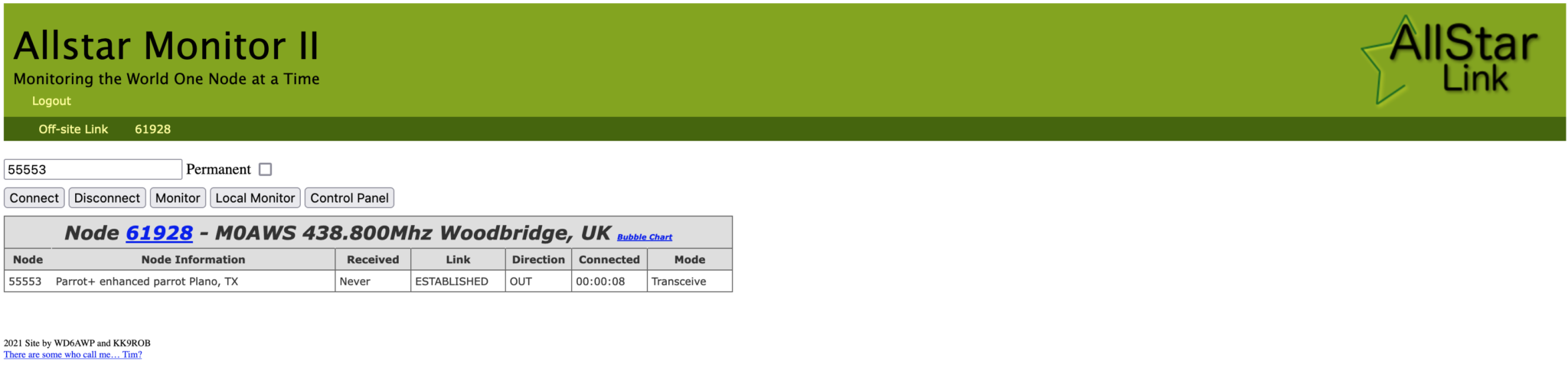
Once connected, tune your radio to 438.800Mhz FM and transmit a test message using your callsign and test123, or something similar. The parrot will then play your recording back to you so that you can hear how you sound. It will also comment on your audio level as to whether it is OK or not.
You are now connected to AllStarLink network and have the world at your finger tips. Below is a small list of nodes in the UK, Australia and America to get you started chatting with other HAMs via your node.
57881	Matrix HAM Radio Space AllStarLink Node (Hosted by Dk1MI)
55553	ASL Parrot for testing
41522	M0HOY HUBNet Manchester, UK
60349	VK6CIA 439.275 Perth, Western Australia
51077	VK6SEG South West Hub B Albany WA
2167	M0JKT FreeSTAR UK HUB 2 freestar.network
53573	NWAG NW AllStar Group Lancashire, UK
27339	East Coast Hub Wilmington NC USA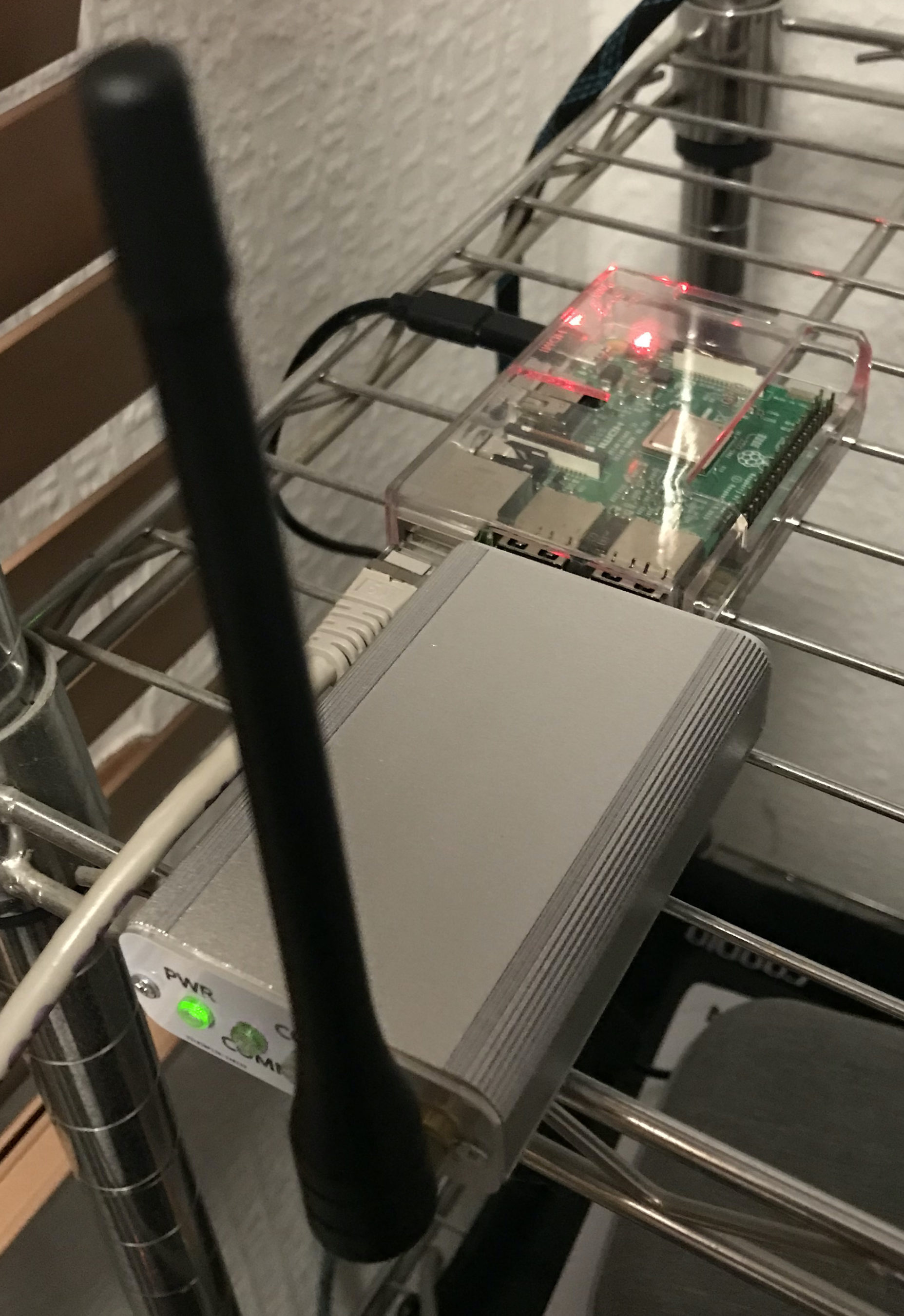
Thanks to Michael, DK1MI for building and hosting the Matrix HAM Radio Space AllStarLink Node (57881) and getting us all started in the world of AllStarLink!
We hope to be having regular Matrix Net’s on the node soon for all Matrix members and visitors. We’ll organise days/times via the Digital Voice room.
More soon …
Following on from my article about my QO-100 Satellite Ground Station Complete Build, this article goes into some detail on the Node-RED section of the build and how I put together my QO-100 Satellite Ground Station Dashboard web app.
The Node-RED project has grown organically as I used the QO-100 satellite over time. Initially this started out as a simple project to synchronise the transmit and receive VFO’s so that the SDR receiver always tracked the IC-705 transmitter.
Over time I added more and more functionality until the QO-100 Ground Station Dashboard became the beast it is today.

Looking at the dashboard web app it looks relatively simple in that it reflects a lot of the functionality that the two radio devices already have in their own rights however, bringing this together is actually more complicated than it first appears.
Starting at the beginning I use FLRig to connect to the IC-705. The connection can be via USB or LAN/Wifi, it makes no difference. Node-RED gains CAT control of the IC-705 via XMLRPC on port 12345 to FLRig.
To control the SDR receiver I use GQRX SDR software and connect to it using RIGCTL on GQRX port 7356 from Node-RED. These two methods of connectivity work well and enables full control of the two radios.

The complete flow above looks rather daunting initially however, breaking it down into its constituent parts makes it much easier to understand.
There are two sections to the flow, the GQRX control which is the more complex of the two flows and the comparatively simple IC-705 section of the flow. These two flows could be broken down further into smaller flows and spread across multiple projects using inter-flow links however, I found it much easier from a debug point of view to have the entire flow in one Node-RED project.
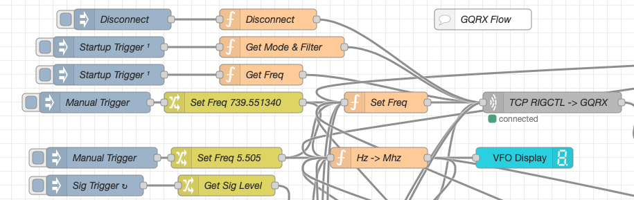
Breaking down the flow further the GQRX startup section (shown below) establishes communication with the GQRX SDR software via TCP/IP and gets the initial mode and filter settings from the SDR software. This information is then used to populate the dashboard web app.
The startup triggers fire just once at initial startup of Node-RED so it’s important that the SDR device is plugged into the PC at boot time.
All the startup triggers feed information into the RIGCTL section of the GQRX flow. This section of the flow (shown below) passes all the commands onto the GQRX SDR software to control the SDR receiver.
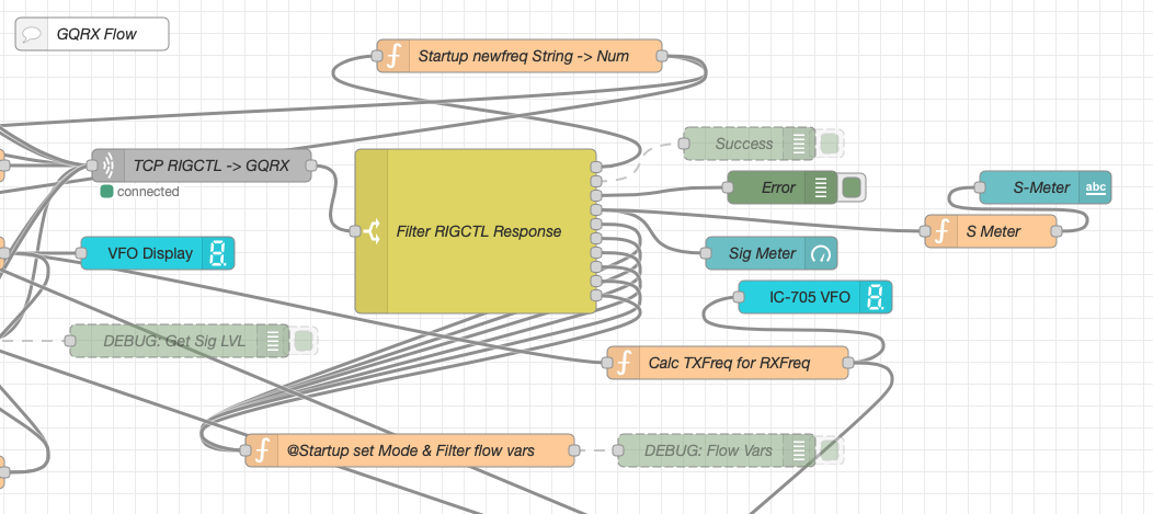
The TCP RIGCTL -> GQRX node is a standard TCP Request node that is configured to talk to the GQRX software on the defined IP Address and Port as configured in the GQRX setup. The output from this node then goes into the Filter RIGCTL Response node that processes the corresponding reply from GQRX for each message sent to it. Errors are trapped in the green Debug node and can be used for debugging.
The receive S Meter is also driven from the the output of the Filter RIGCTL Response node and passed onto the S Meter function for formatting before being passed through to the actual gauge on the dashboard.
Continuing down the left hand side of the flow we move into the section where all the GQRX controls are defined.
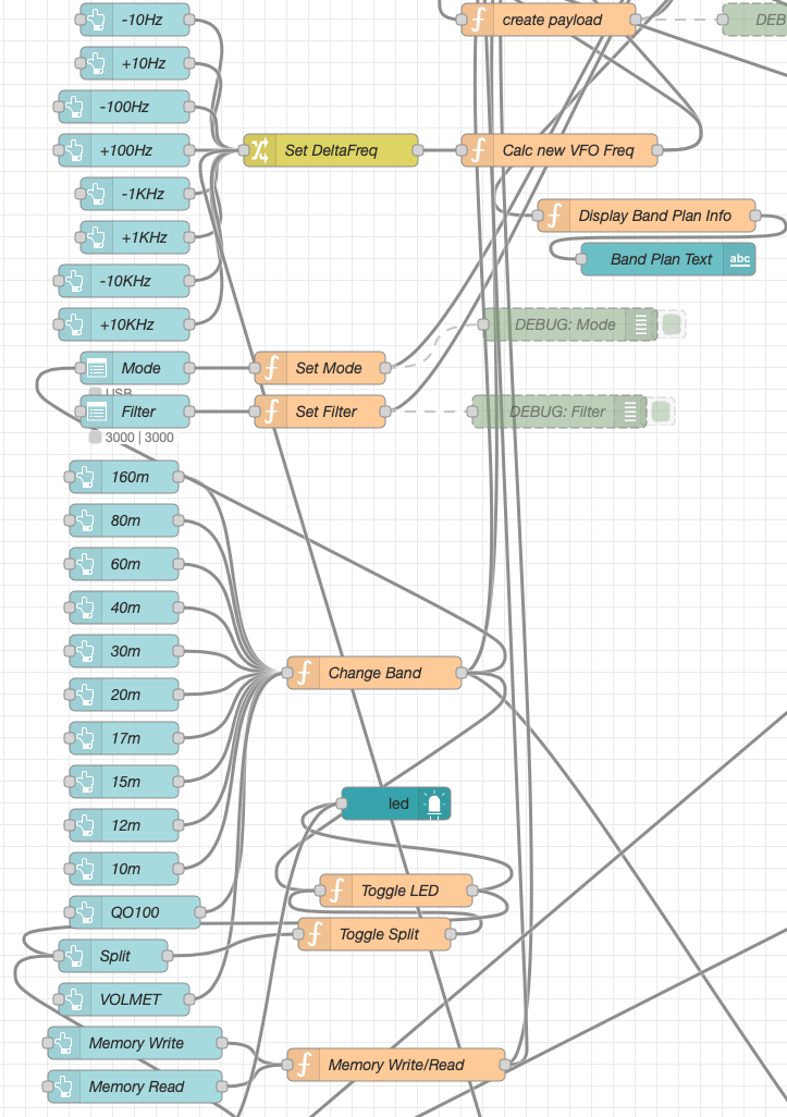
In this section we have the VFO step buttons that move the VFO up/down in steps of 10Hz to 10Khz. Each button press generates a value that is passed onto the Set DeltaFreq change node and then on to the Calc new VFO Freq function. From here the new VFO frequency is stored and passed onto the communications channel to send the new VFO frequency to the GQRX software.
The Mode and Filter nodes are simple drop down menus with predefined values that are used to change the mode and receive filter width of the SDR receiver.
Below are the HAM band selector buttons, each of these will use a similar process as detailed above to change the VFO frequency to a preset value on each of the HAM HF Bands.
The QO-100 button puts the transmit and receive VFO’s into synchro-mode so that the receive VFO follows the transmit VFO. It also sets the correct frequency in the 739Mhz band for the downlink from the LNB in GQRX SDR software and sets the IC-705 to the correct frequency in the 2m VHF HAM band to drive the 2.4Ghz up-converter.
The Split button allows the receive VFO to be moved away from the transmit VFO for split operation when in QO-100 mode. This allows for the receive VFO to be moved away so that you can RIT into slightly off frequency stations or to work split when working DXpedition stations.
The bottom two Memory buttons allow you to store the current receive frequency into a memory for later recall.
At the top right of this section of the flow there is a Display Band Plan Info function, this displays the band plan information for the QO-100 satellite in a small display field on the Dashboard as you tune across the transponder. Currently it only displays information for the satellite, at some point in the future I will add the necessary code to display band plan information for the HF bands too.
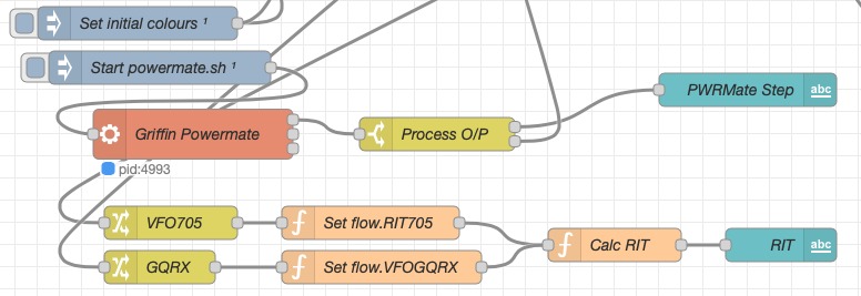
The final section of the GQRX flow (shown below) sets the initial button colours and starts the Powermate USB VFO knob flow. I’ve already written a detailed article on how this works here but, for completeness it is triggered a few seconds after startup (to allow the USB device to be found) and then starts the BASH script that is used to communicate with the USB device. The output of this is processed and passed back into the VFO control part of the flow so that the receive VFO can be manually altered when in split mode or in non-QO-100 mode.
The bottom flows in the image above set some flow variables that are used throughout the flow and then calculates and sets the RIT value on the dashboard display.
The final section of the flow is the IC-705 control flow. This is a relatively simple flow that is used to both send and receive data to/from the IC-705, process it and pass it on to the other parts of the flow as required.
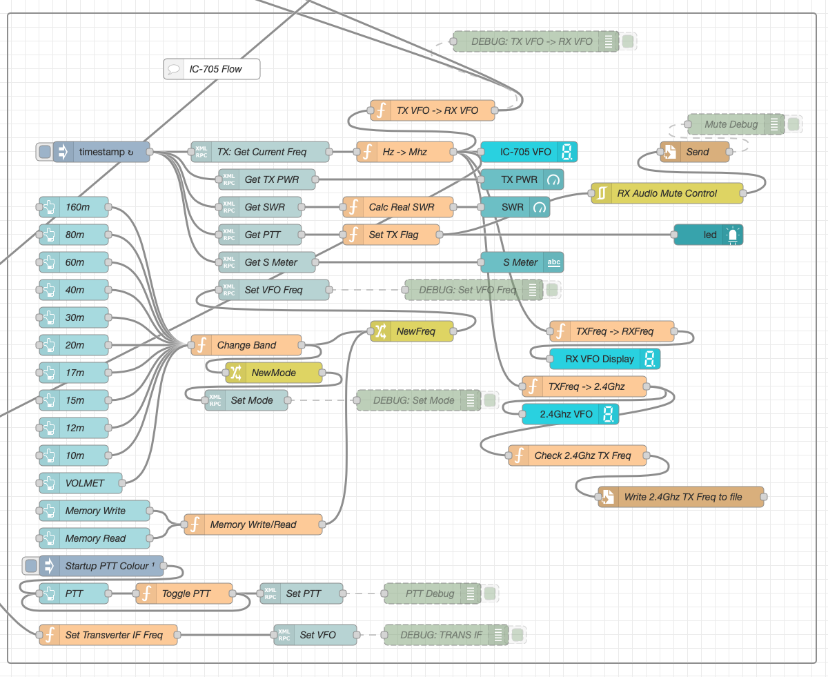
The IC-705 flow is started via the timestamp trigger at the top left. This node is nothing more than a trigger that fires every 0.5 seconds so that the dashboard display is updated in near realtime. The flow is pretty self explanatory, in that it collects the current frequency, transmit power, SWR reading, PTT on/off status and S Meter reading each time it is triggered. This information is then processed and used to keep the dashboard display up to date and to provide VFO tracking information to the GQRX receive flow.
On the left are the buttons to change band on the IC-705 along with a button to tune to the VOLEMT on the 60m band. Once again there two memory buttons to save and recall the IC-705 VFO frequency.
The Startup PTT Colour trigger node sets the PTT button to green on startup. The PTT button changes to red during transmit and is controlled via the Toggle PTT function.
At the very bottom of the flow is the set transverter IF Freq function, this sets the IC-705 to a preselected frequency in the 2m HAM band when the dashboard is switched into QO-100 mode by pressing the QO-100 button.
On the right of the flow there is a standard file write node that writes the 2.4Ghz QO-100 uplink frequency each time it changes into a file that is used by my own logging software to add the uplink frequency into my log entries automatically. (Yes I wrote my own logging software!)
The RX Audio Mute Control filter node is used to reduce the receive volume during transmit when in QO-100 full duplex mode otherwise, the operator can get tongue tied hearing their own voice 250ms after they’ve spoken coming back from the satellite. This uses the pulse audio system found on the Linux platform. The audio is reduced to a level whereby it makes it much easier to talk but, you can still hear enough of your audio to ensure that you have a good, clean signal on the satellite.
As I said at the beginning of this article, this flow has grown organically over the last 12 months and has been a fun project to put together. I’ve had many people ask me how I have created the dashboard and whether they could do the same for their ground station. The simple answer is yes, you can use this flow with any kind of radio as long as it has the ability to be controlled via CAT/USB or TCP/IP using XMLRPC or RIGCTL.
To this end I include below an export of the complete flow that can be imported into your own Node-RED flow editor. You may need to make changes to it for it to work with your radio/SDR but, it shouldn’t take too much to complete. If like me you are using an IC-705 and any kind of SDR controlled by GQRX SDR software then it’s ready to go without any changes at all.
More soon …
Ever since my QO-100 ground station has been operational I’ve been using my NodeRed QO-100 Dashboard to control my IC-705 and GQRX SDR software to drive my NooElec SmartSDR receiver. This gives me a full duplex ground station with both transmit and receive VFO’s synchronised.
This solution has worked incredibly well from the outset and over time I’ve added extra functionality that I’ve found to be useful to enhance the overall setup.
The latest addition to the ground station solution is a Sennheiser Headset that I picked up for just £56 on Amazon (Much cheaper than the Heil equivalents at the HAM stores!) and have found it to be excellent. The audio quality from both the mic and the headphones is extremely good whilst being light and comfortable to wear for extended periods.

To incorporate this into the ground station the headset is connected to my Kubuntu PC and the audio chain to the IC-705 is sent wirelessly using the latest version of WFView. This works extremely well. The receive audio comes directly from the GQRX SDR software to the headphones so that I have a full duplex headset combination.
Audio routing is done via pulse audio on the Kubuntu PC and is very easy to setup.
Since I no longer have a mic connected to the IC-705 directly I found that I needed a way to operate the PTT wirelessly and this is where the latest addition to my NodeRed QO-100 Dashboard comes in.
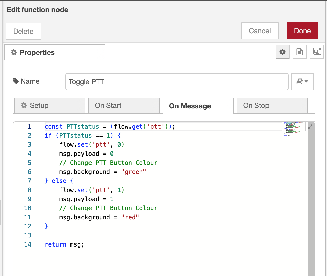
Adding a little functionality to the NodeRed flow I was able to create a button that toggles the IC-705 PTT state on and off giving me the ability to easily switch between receive and transmit using a simple XMLRPC node without the need for a physical PTT button.
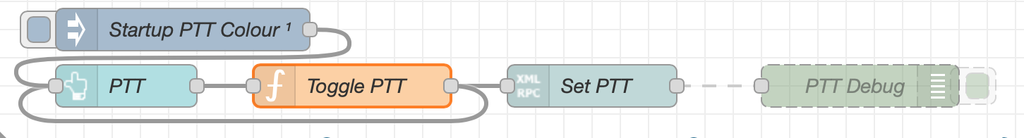
The PTT state and PTT button colour change is handled by the Toggle PTT function node shown in the above flow. The code to do this is relatively simple as shown below.
The entire QO-100 Dashboard flow has grown somewhat from it’s initial conception but, it provides all the functionality that I require to operate a full duplex station on the QO-100 satellite.

This simple but, effective PTT solution works great and leaves me hands free whilst talking on the satellite or the HF bands when using the IC-705. This also means that when using my IC-705 it only requires the coax to be connected, everything else is done via Wifi keeping things nice and tidy in the radio shack.

The image above shows the QO-100 ground station in receive cycle with the RX/TX VFO’s in split mode as the DX station was slightly off frequency to me. The PTT button goes red when in TX mode just like the split button shown above for visual reference.
As you can probably tell, I’m a huge fan of NodeRed and have put together quite a few projects using it, including my HF Bands Live Monitoring web page.
More soon …
I’ve got a couple of old RaspberryPi computers on the shelf in the shack and so decided it was time for me to put one of them to good use. The first model on the shelf is the oldest and is one of the very first RaspberryPi 1 computers that was released. (It’s the one with the yellow analog video signal output on the board!). This particular model is extremely slow but, I hang onto it just as a reminder of the first SBC in the line.
The second one is a RaspberryPi 2, a quad core machine that is only slightly faster than the first model but, it’s powerful enough to run HAM Clock.
It didn’t take long to install a vanilla Raspbian Desktop O/S and get it configured on the local LAN. I installed a few packages that I like to have available on all my Linux machines and then started on the HAM Clock install.
The first thing I needed to do was install the X11 development library that is required to compile the HAM Clock binary. To do this, open a terminal and enter the command below to install the package.
sudo apt install libx11-devYou will need to type in your password to obtain root privileges to complete the installation process and then wait for the package to be installed.
The HAM Clock source code is available from the HAM Clock Website under the Download tab in .zip format. Once downloaded unzip the file and change directory into the ESPHamClock folder ready to compile the code.
cd ~/Downloads/ESPHamClockOnce in the ESPHamClock directory you can run a command to get details on how to compile the source code.
make helpThis will check your system to see what screen resolutions are available and then list out the options available to you for compiling the code as shown below.
The following targets are available (as appropriate for your system)

    hamclock-800x480          X11 GUI desktop version, AKA hamclock
    hamclock-1600x960         X11 GUI desktop version, larger, AKA hamclock-big
    hamclock-2400x1440        X11 GUI desktop version, larger yet
    hamclock-3200x1920        X11 GUI desktop version, huge

    hamclock-web-800x480      web server only (no display)
    hamclock-web-1600x960     web server only (no display), larger
    hamclock-web-2400x1440    web server only (no display), larger yet
    hamclock-web-3200x1920    web server only (no display), huge

    hamclock-fb0-800x480      RPi stand-alone /dev/fb0, AKA hamclock-fb0-small
    hamclock-fb0-1600x960     RPi stand-alone /dev/fb0, larger, AKA hamclock-fb0
    hamclock-fb0-2400x1440    RPi stand-alone /dev/fb0, larger yet
    hamclock-fb0-3200x1920    RPi stand-alone /dev/fb0, huge
For my system 1600×960 was the best option and so I compiled the code using the command as follows.
make hamclock-1600x960It’s no surprise that it takes a while to compile the code on such a low powered device. I can’t tell you how long exactly as I went and made a brew and did a few other things whilst it was running but, it took a while!
Once the compilation was complete you then need to install the application to your desktop environment and move the binary to the correct directory.
make installOnce the install is complete there should be an icon on the GUI desktop to start the app. If like mine it didn’t create the icon then you can start the HAM Clock by using the following command in the terminal.
/usr/local/bin/hamclock &The first time you start the app you’ll need to enter your station information, callsign, location etc and then select the settings you want to use. There are 4 pages of options for configuring the app all of which are described in the user documentation.

Once the configuration is complete the map will populate with the default panels and data. I tailored my panels to show the items of interest to me namely, POTA, SOTA, International Beacon Project and the ISS space station track. I was hoping to be able to display more than one satellite at a time on the map however, the interface only allows for one bird to be tracked at a time.
You can access the HAM Clock from another computer using a web browser pointed at your RaspberryPi on your local LAN using either the IP address or the hostname of the device.
http://<hostname>:8081/live.html

or

http://<ip-address>:8081/live.html
You can also control the HAM Clock remotely via web browser using a set of web commands that are detailed on port 8080 of the device.
http://<hostname or ip-address>:8080/
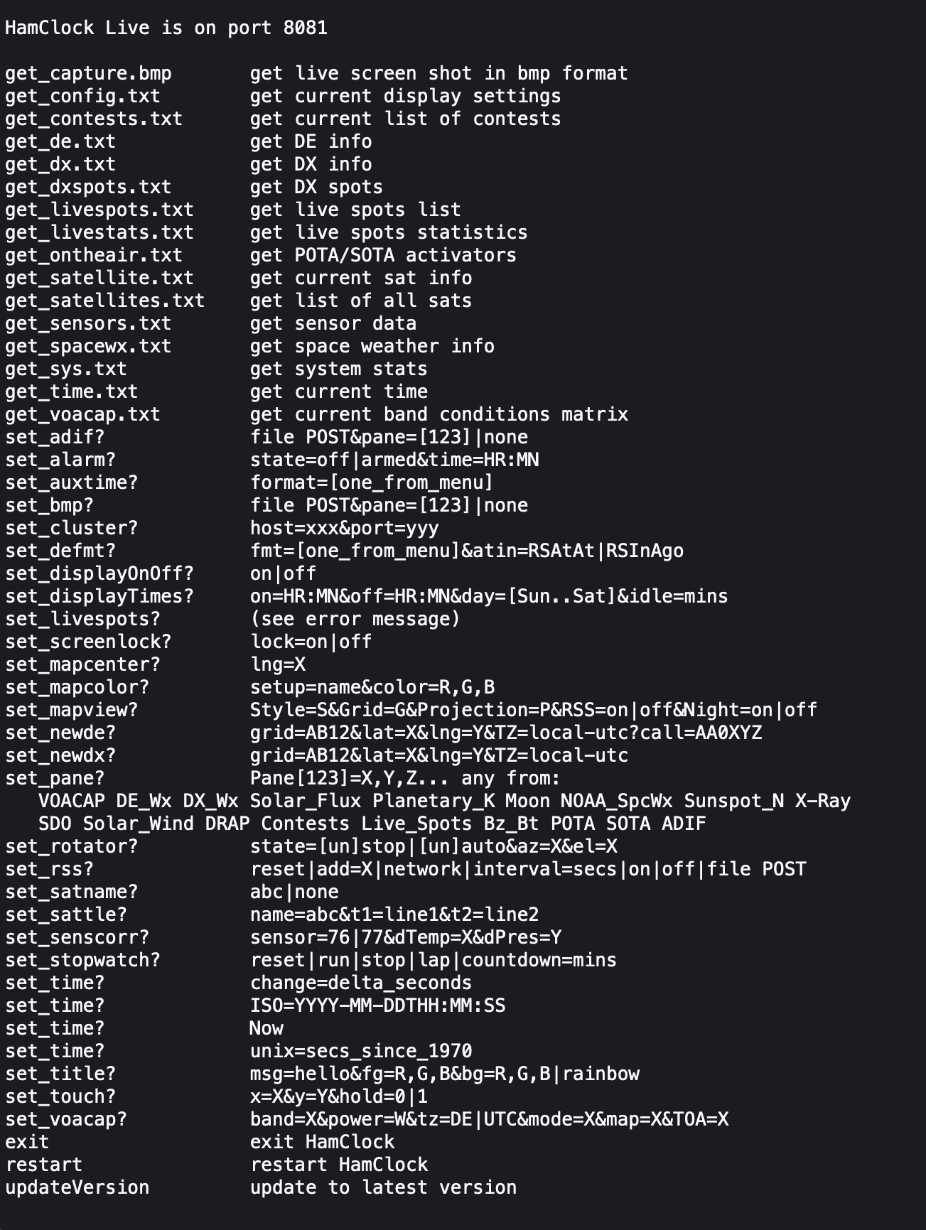
This is a great addition to any HAM shack especially if, like me you have an old HDTV on the wall of the shack that is crying out to display something useful.
More soon …
This blog exists for me to catalog sucesses and failures. The other thing it does is provide me with a place to put things so that I can get to them no matter where I am assuming – an internet connection. The topic for today is a refresher on my setup for my portable digital operations.
This discussion centers around the use of the IC-705 and the Microsoft Surface GO 2. I have no reason to believe that changing the computer will make any difference as I have gotten this working on other laptops, but the operating system will require some attention.
I’m running Ubuntu as my Linux distro on this device. There is pre-reading required to make this all work and we’ll get to that in a second.
Software includes the following from the Ubuntu repository:
I am currently using the fork of ardop known as – ardopcf from pflarue on GitHub. New and exciting things are happening here in the world of ardop.
There is a great set of instructions on how to get ALSA loopback devices set up appropriately for wfview in their well-written user manual. Start here:
With all of that done and in place, there are a few things to look at in wfview for rig control to make life a little easier. At the bottom of this page of the wfview manual there is some good information on setting up wfview to do what flrig would do. That’s what I do. Why? Because it’s working and keeps things simple. The important thing, in my experience, is to set the port number to something other than 4532 which is the flrig default. I set it to 4533 because that’s a safe port number.
Here is what my wfview External Control tab looks like:
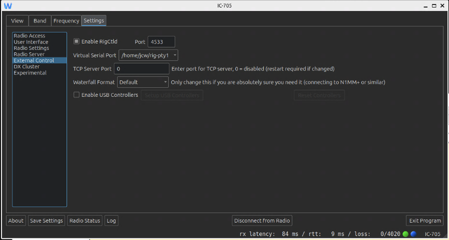
It should be noted that I’m using the Virtual Serial Port. This is a mapping to /dev/pty/NUMBER and it takes care of itself once set up.
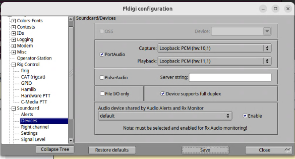
With wfview up and running, setting up fldigi is relatively simple. The following configurations for audio and rig control are currently working.
The rig control settings are set on the HamLib segment of the Rig Control section in the configuration dialogue.
Use hamlib is selected.
Rig is set to Hamlib NET rigctl (stable)
Device is set to 127.0.0.1:4553 (as found in wfview)
Baud rate is set to 115200
All other settings are defaults.
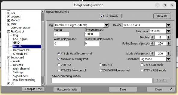
With this complete, save and initialize the connection and then go to the main fldigi window to tune or send a station ID. Rig control and audio should function as expected.
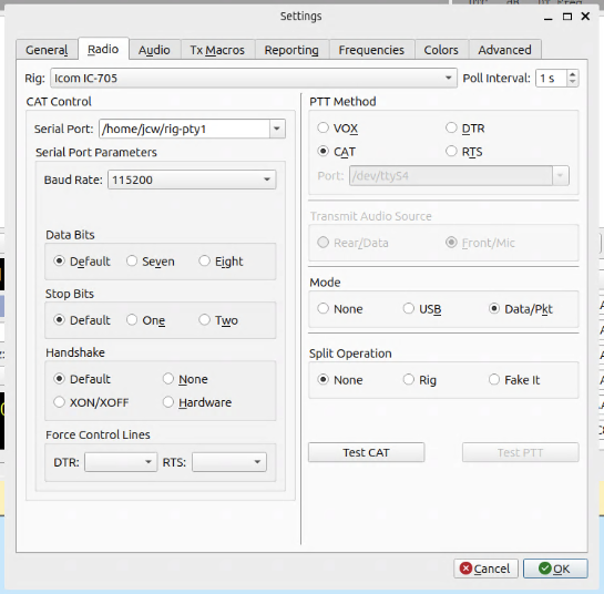
WSJT-X is the odd duck. My dad and I have the rig control configured differently, but it still works for both of us. What does that mean? There might be more than one successful configuration so maybe find what works and don’t touch it after that. What I use is listed here.
The Radio settings tab is configured as follows.
Rig: Icom IC-705
Serial Port: /home/jcw/rig-pty-1
Baud Rate: 115200
PTT Method: CAT
Data Bits: Default
Stop Bits: Default
Handshake: Default
Mode: Data/Pkt
Split Operation: None
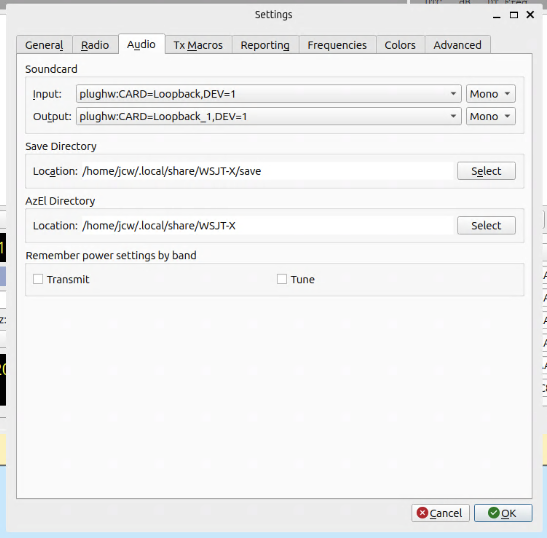
The Audio setup matches the devices that are set in wfview but in reverse.
Note: I find the labeling in wfview to be counterintuitive. It’s probably just my broken brain, but I have to remind myself to flip things around and think about it as source/destination pairs. It’s probably just me.
The Audio tab is configured as follows.
Input: plughw:CARD=Loopback,DEV=1
Output: plughw:CARD=Loopback_1,DEV=1
With this configuration in place, one can test the rig control on the Radio tab or by going to the main window and changing frequencies. Running a tuning cycle briefly will test audio output.
ardopcf is available on GitHub as a binary. Simply download it and put it in /usr/local/bin, run a quick chmod+x on it, and it should be good to go. That’s all that it required of me.
With ardopcf in place, lauching ardop is fairly simple. I put it in a little script so that I don’t have to type out the arguments each time. I named the script “startardop.sh” and dumped it in my home directory. Creative, huh? Here’s what it looks like:
ardopcf 8515 plughw:CARD=Loopback,DEV=1 plughw:CARD=Loopback_1,DEV=1
When you start ardopcf, you should start to see pairs of numbers in the terminal showing you audio input levels. If you’re getting a lot of 0,0 then you might have a problem or wfview might not be running. Maybe your rig is off? Check your signal chain. If, on the other hand, you’re seeing numbers pop up every 4 seconds or so, then you’re in good shape.
Pat requires some homework and I’m just going to dump some output here. There are instructions for configuration here: https://github.com/la5nta/pat/wiki/The-command-line-interface
The crux of the matter is configuring ~/.config/pat/config.json. Your mileage is going to vary here, but my config looks like this:
{
"mycall": "KC8JC",
"secure_login_password": "NOTPUTTINGTHATONTHEBLOG-HAHAHA!",
"auxiliary_addresses": [],
"locator": "EN91hd",
"service_codes": [
"PUBLIC"
],
"http_addr": "localhost:8080",
"motd": [
"Open source Winlink client - getpat.io"
],
"connect_aliases": {
"telnet": "telnet://{mycall}:CMSTelnet@cms.winlink.org:8772/wl2k"
},
"listen": [],
"hamlib_rigs": {
"my_ic705": {"address": "localhost:4533", "network": "tcp"}
},
"ax25": {
"port": "wl2k",
"beacon": {
"every": 3600,
"message": "Winlink P2P",
"destination": "IDENT"
},
"rig": "my_ic705",
"ptt_ctrl": true,
"beacon_interval": 0,
"cwid_enabled": true
},
"serial-tnc": {
"path": "/dev/ttyUSB0",
"serial_baud": 9600,
"hbaud": 1200,
"type": "Kenwood"
},
"ardop": {
"addr": "localhost:8515",
"arq_bandwidth": {
"Forced": false,
"Max": 2000
},
"rig": "my_ic705",
"ptt_ctrl": true,
"beacon_interval": 0,
"cwid_enabled": true
},
"pactor": {
"path": "/dev/ttyUSB0",
"baudrate": 57600,
"rig": "",
"custom_init_script": ""
},
"telnet": {
"listen_addr": ":8774",
"password": ""
},
"varahf": {
"host": "localhost",
"cmdPort": 8300,
"dataPort": 8301,
"bandwidth": 2300,
"rig": "",
"ptt_ctrl": false
},
"varafm": {
"host": "localhost",
"cmdPort": 8300,
"dataPort": 8301,
"bandwidth": 0,
"rig": "",
"ptt_ctrl": false
},
"gpsd": {
"enable_http": false,
"allow_forms": false,
"use_server_time": false,
"addr": "localhost:2947"
},
"schedule": {},
"version_reporting_disabled": false
}
Wow. That’s a lot of stuff. That is the configuration that is currently working for me for sending Winlink email using ARDOP or telnet.
What a lot of people seem to miss is that Pat has a web gui that will run on localhost:8080. It makes using Pat a lot easier and gives a fresh, modern GUI to Winlink email. And yes, it handles forms and everything. It’s pretty darned cool!
To get that up and running, I use yet another creatively named script: startpat.sh. The contents of that are:
pat-winlink --listen "ardop,ax25,telnet" http
What does that do? It starts up Pat listening for connections on ardop, ax25, or telnet. I didn’t detail ax25 here because, well, I’m not done playing with that just yet. And telnet should always be there so that you can use Pat if you have a good internet connection and NEED to check your Winlink email. The http argument starts the application listening on 8080 for the web UI. With Pat running, all you have to do is go to https://localhost:8080/ui and you’ll see the web UI. You’re now free to explore Pat and send/receive Winlink email.
This is the setup that is currently working for me. I will update this as I add other modes, etc.
![]()
I’ve just added an IC-9700 to the desk alongside the IC-7300, they look very nice together and very similar. Unfortunately the Audio and Serial devices also look very similar in Linux!

Both radio sound cards appear as PCM2901 making it hard to differentiate between them, and my previous udev rule to create a symlink for the IC-7300 ttyUSB device on /dev/ic7300 picked up the 9700 instead.
My previous udev serial rule created a symlink to /dev/ttyUSBx from /dev/ic7300 when a device with the 7300’s serial adapter idVendor and idProduct was seen like so:
SUBSYSTEM==”tty”, ATTRS{idVendor}==”10c4″, ATTRS{idProduct}==”ea60″ SYMLINK+=”ic7300″
This worked fine until the 9700 was plugged in as it also has the same idVendor and idProduct number. We can narrow this down easily as another available attribute is “serial” which contains the radios unique serial number along with its name.
We can get the serial numbers using udevadm (or better with lsusb below) against each of the /dev/ttyUSBx devices, the 9700 has two serial devices, the first works fine with hamlib for control but not sure what the second serial device at the moment.
$ udevadm info –attribute-walk –path=/sys/bus/usb-serial/devices/ttyUSB4 | grep IC-
ATTRS{serial}==”IC-9700 13000000 A”$ udevadm info –attribute-walk –path=/sys/bus/usb-serial/devices/ttyUSB5 | grep IC-
ATTRS{serial}==”IC-9700 13000000 B”$ udevadm info –attribute-walk –path=/sys/bus/usb-serial/devices/ttyUSB1 | grep IC-
ATTRS{serial}==”IC-7300 03000000″
An easier way to get the serial numbers is by running lsusb as root as follows, thanks to PA3MET for the pointer!
# lsusb -vvvvv | egrep "9700|7300"
iSerial 3 IC-9700 13000000 B
iSerial 3 IC-9700 13000000 A
iSerial 3 IC-7300 03000000
We can take these and create appropriate udev rules for adding symlinks for the radios serial devices including the unique serial numbers. Here is an extract from my /etc/udev/rules.d/99-hamlib.rules file:
SUBSYSTEM==”tty”, ATTRS{idVendor}==”10c4″, ATTRS{idProduct}==”ea60″, ATTRS{serial}==”IC-7300 03000000″, SYMLINK+=”ic7300″
SUBSYSTEM==”tty”, ATTRS{idVendor}==”10c4″, ATTRS{idProduct}==”ea60″, ATTRS{serial}==”IC-9700 13000000 A”, SYMLINK+=”ic9700a”
SUBSYSTEM==”tty”, ATTRS{idVendor}==”10c4″, ATTRS{idProduct}==”ea60″, ATTRS{serial}==”IC-9700 13000000 B”, SYMLINK+=”ic9700b”
Take care if copying the above text as the quotation marks are displaying incorrectly in WordPress. If you copy it as is you will need to replace them all with proper quotation marks.
A reload of udev rules with “udevadm trigger” and we have our serial devices available from convenient symlinks so no chasing about ttyUSB device names:
$ ls -l /dev/ic*
lrwxrwxrwx 1 root root 7 Apr 4 14:27 /dev/ic7300 -> ttyUSB1
lrwxrwxrwx 1 root root 7 Apr 4 14:27 /dev/ic9700a -> ttyUSB4
lrwxrwxrwx 1 root root 7 Apr 4 14:27 /dev/ic9700b -> ttyUSB5
Next up is the sound cards. I use quite a lot of different programs and need to easily switch and adjust my audio inputs/outputs using pavucontrol. The problem here is both audio devices have the same name, PCM2901, meaning I can’t easily tell what sound card belongs to what radio.
There’s no way to differentiate the sound cards like with the serial above as they return the exact same information and attributes. The only way to differentiate them from what I can see is with the physical USB port they are plugged in to. This is fine here as it’s a desktop and they will remain plugged in to the same ports. If you plug the radios in to a different USB socket you will need to update the paths again.
We can list the devices with the following command, this shows both the IC-7300 and IC-9700 sound cards. I’ve removed some other sound cards from the output, as we’re just looking for the “Burr-Brown_from_TI_USB_Audio_CODEC” entries here
$ pacmd list-sources | egrep “name:|sysfs”
name: <alsa_output.usb-Burr-Brown_from_TI_USB_Audio_CODEC-00.analog-stereo.2.monitor>
sysfs.path = “/devices/pci0000:00/0000:00:14.0/usb3/3-2/3-2.4/3-2.4:1.0/sound/card4”
name: <alsa_input.usb-Burr-Brown_from_TI_USB_Audio_CODEC-00.analog-stereo.2>
sysfs.path = “/devices/pci0000:00/0000:00:14.0/usb3/3-2/3-2.4/3-2.4:1.0/sound/card4″
name: <alsa_output.usb-Burr-Brown_from_TI_USB_Audio_CODEC-00.analog-stereo.3.monitor>
sysfs.path = “/devices/pci0000:00/0000:00:14.0/usb3/3-3/3-3.4/3-3.4:1.0/sound/card5”
name: <alsa_input.usb-Burr-Brown_from_TI_USB_Audio_CODEC-00.analog-stereo.3>
sysfs.path = “/devices/pci0000:00/0000:00:14.0/usb3/3-3/3-3.4/3-3.4:1.0/sound/card5″
We are looking to extract the unique portion from device paths above, here we can see the paths differ at 3-3/3-3.4/3-3.4 and 3-2/3-2.4/3-2.4. We will want to identify which entry belongs to which radio so run it with the USB disconnected then connected to identify which device matches which radio.
We can then run the following to apply a device description of IC9700 to the IC-9700 sound card source and sink which will show against the audio device in pulse applications instead of PCM2901.
The 3-3.4 below is referencing the end of the USB port discovered above.
pacmd update-source-proplist $(pacmd list-sources | egrep “name:.*Burr-Brown*|3-3.4” | grep -B 1 sysfs.path | grep name | sed “s/.*<\(.*\)>/\1/” | grep -v monitor) device.description=IC9700
pacmd update-sink-proplist $(pacmd list-sinks | egrep “name:.*Burr-Brown*|3-3.4” | grep -B 1 sysfs.path | grep name | sed “s/.*<\(.*\)>/\1/”) device.description=IC9700
And the same for the IC7300 with 3-2.4:
pacmd update-source-proplist $(pacmd list-sources | egrep “name:.*Burr-Brown*|3-2.4” | grep -B 1 sysfs.path | grep name | sed “s/.*<\(.*\)>/\1/” | grep -v monitor) device.description=IC7300
pacmd update-sink-proplist $(pacmd list-sinks | egrep “name:.*Burr-Brown*|3-2.4” | grep -B 1 sysfs.path | grep name | sed “s/.*<\(.*\)>/\1/”) device.description=IC7300
The audio devices should now be available using the name we set above in pavucontrol and other applications. This can be put in a script to run manually or at system startup.

