Reading view

There are new articles available, click to refresh the page.

Transformers and magnetic saturation

It seems that even a basic but sound understanding of transformers challenges lots of hams, and even online experts that have been heard to brag of their qualifications so as to intimidate others who might question their words.

So at ARRL EFHW (hfkits.com) antenna kit transformer – revised design #1 – part 2 I estimated that at a current of 4Arms marked the onset of non-linear B-H response, ie the onset of saturation.

One online expert proposed a method that would rate this transformer at maximum 4^2*50=800W at which magnetic saturation would occur.

The referenced article estimated saturation at more like 17000W.

Some very basic transformer concepts

Let’s talk about some really basic transformer concepts.

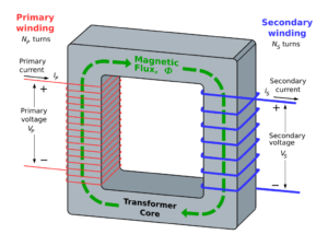
The diagram above from Wikepedia shows a rectangular magnetic core with two windings, a primary and secondary on opposite limbs of the core.

Note the phase polarity markings (+ / -) and the direction of (conventional) alternating current.

An example for discussion

Above is an example power transformer for discussion, 240V 50Hz 100VA, n=Vs/Vp=1/20, rated primary current 0.416A, core mass around 800g, estimated core loss at 1W/kg is 0.8W, for a simple explanation, leakage is assumed zero and rated load is assumed purely resistive. Note that an AC power transformer is typically rated for primary voltage, frequency and VA, and that they are operated into the low end of BH saturation, a compromise between weight, dissipation and efficiency (and cost of course).

Let’s assume that it is a good design, and for a first analysis, let’s ignore flux leakage, ie flux due to current in one winding that does not induce voltage in the other winding (does not ‘cut’ the other winding). Let’s analyse it with no load and rated load.

No load

With load load, assume zero current flows in the secondary.

The primary winding acts like an iron cored inductor, when voltage is applied, current flows. The current produces magnetic flux and a voltage induced in the primary winding which by Lenz’s law opposes the voltage that created the current.

The current that flows with no-load is known as the magnetising current, it establishes magnetic flux in the core. In a good design, the magnetising current is small wrt rated current. We can extend that and talk of the corresponding magnetising impedance and the magnetising admittance.

For the example 50Hz transformer shown, the magnitude of magnetising current is 12mA, 2.9% of rated current. Magnetising current is a component of primary current in a loaded transformer.

You might at first think that the magnetising impedance Zm is purely inductive, but that would make it lossless and nothing is lossless. In the example case, the phase of Zm is 74°, Zm=5556+j19213Ω.

Magnetising force is given by \(mmf=n(I_p +0.012 \angle -74°  – \frac{I_s}{n})=n 0.012 \angle -74° \text{At/m}\).

Rated load

So, when rated current flows in the secondary, it induces a voltage component in the primary winding that opposes the voltage induced in the primary by the magnetising current component, so more primary current flows… rated primary current in a zero leakage scenario.

Print the diagram and annotate it with a pencil, and work through Lenz’s law and the direction of current. Sure, I could have done it, but you will learn more by working through the solutions, you will remember it better, and get confidence in your growing analytical capability.

So, the primary current under rated load is the load current divided by the turns ratio, plus the magnetising current. In this example, Ip=0.416-0.012∠-74°.

Why does the core not saturate?

You need to calculate the net magnetising force by adding the primary and secondary magnetising force components. In this case, recalling that Is=Ip/n for our scenario, \(mmf=n(I_p +0.012 \angle -74°  – \frac{I_s}{n})=n 0.012 \angle -74° \text{At/m}\), the same as the no-load magnetising force.

Note that when leakage inductance and winding resistance are factored in, loaded magnetising force is usually a little less than no-load.

If load current does not cause saturation, what does?

Two common causes:

  • operating at lower that rated frequency; and
  • operating at higher than rated voltage.

Because the B-H response is non-linear, a small increase in primary voltage creates a disproportionate increase in core less (due to higher flux density).

But my guitar amp can be driven to transformer saturation!

Sure, it is being driven to higher voltage and or lower frequencies than the design point, both of which contribute to saturation. Changing the load impedance does not directly cause magnetic saturation.

My ferrite cored EFHW transformer is easily saturated!

Probably not. Naive users often incorrectly blame overheating of the ferrite core beyond the Curie point as magnetic saturation.

Conclusions

  • Lenz’s Law is key to understanding.
  • Increasing primary voltage or lowering frequency can cause magnetic saturation.
  • Increasing load current alone is unlikely to cause magnetic saturation.
  • Other non-linear behavior is often wrongly attributed to magnetic saturation.
Last update: 5th October, 2024, 5:04 PM

ARRL EFHW (hfkits.com) antenna kit transformer – revised design #1 – part 2

This article continues on from several articles that discussed the ARRL EFHW kit transformer, apparently made by hfkits.com, and the revised design at ARRL EFHW (hfkits.com) antenna kit transformer – revised design #1 – part 1.

This article presents a saturation calculation.

You will not often see saturation calcs (for reasons that will become apparent), though you will hear uninformed discussion promoting FUD (fear, uncertainty and doubt).

Lets assume that the core is capable of maximum continuous power dissipation of 10W (limited by factors like safe enclosure temperature, human safety, Curie point etc).

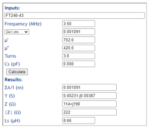
Now let’s estimate the magnetising current for 10W of core dissipation with 3t primary

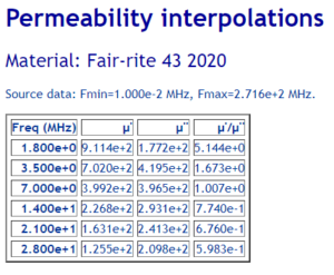
Starting with the expected permeability above…

Gm is the magnetising conductance, the real part of Y above, 0.00231.

We can approximate the primary voltage for 10W core dissipation as \(V=(\frac{P}{G_m})^{0.5}=(\frac{10}{0.00231})^{0.5}=65.8V\) which implies 87W in a 50Ω load.

Magnetising current can be calculated at 10W core dissipation as \(I_m=\frac{V}{|Z|}=\frac{65.8}{222}=0.296A\)

In fact, under load, the net magnetising force may be just a little below 0.296A due to the effects of leakage inductance.

Let’s estimate saturation current for a 3t primary

Lets assume that under load, magnetising force due to current in the secondary offsets most of the magnetising force due to current in the primary and that the net magnetising force is due to magnetising current.

So, let’s solve.

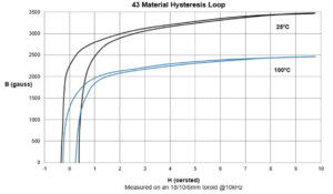
Above is Fair-rite’s published data for their #43 mix (do not assume it applies to pretenders). Let’s take saturation flux density to be 1500 gauss, 0.15T.

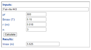
Above is a calc of the saturation current for the 3t primary (peak), 4.01 Arms.

Conclusions

The saturation current is 14 times the magnetising current at 10W core dissipation, and is unlikely to be a significant limitation for low duty cycle modes.

This EFHW transformer is loss limited rather than saturation limited for most practical applications.

If you had in mind that this transformer was suited to peak power \(14^2 \cdot 87=17000 \text{ W}\) or more, then it may be driven into saturation.

Last update: 4th October, 2024, 6:01 AM

Back home a week later

It was a great time being back in Ottawa, visiting with friends from my old neighborhood and also spoiling my Daughters two cats.

However on the “Radio side” of things …. not so good

The plans were that I would be able (weather permitting) continue to control my hour on the Trans Provincial Net while away. It seemed that “Mother Nature” had different ideas. Most days rain or the threat of rain kept me from heading over to the park.

Above pic showing where the park was and the route I took

As I mentioned in a previous post…. there was a local (non-POTA) park within walking distance to operate from. It was a local sports field and had some bleachers for when the crowds came for Junior Soccer/Football and or Rugby…

Below pic showing how I set up at the park

Although the operating position was excellent there was NO PROTECTION from the elements which in my case meant rain.

I was able to wrap my MFJ mast to one of the bleachers and stretch the end of the EFHW antenna to the other bleacher and it did work like a charm. Signal reports were great considering I was running 50w into the antenna

So for 1 out of a potential 5 operating days it was fun and dry. Walking home with the gear safely packed in the backpack “Mother Nature” paid a short visit.

I also managed to activate CA1515 and CA1516 using my Xiegu X5105 along with a 29 foot wire (supported by the same mast mentioned earlier) with a 9:1 unun, a 17 foot counterpoise with a choke on the radio end of the coax. Jose VA3PCJ was nice enough to offer me a ride there and back. I activated the parks using SSB and VA3PCJ activated the same parks using CW and his KX3.

For Jose’s version of the park activation click HERE

I am expecting to be returning to Ottawa in Mid-January 2025 for another visit with my GrandKits and like last years winter visit there will be a car to keep me warm and dry.

73bob

ARRL EFHW (hfkits.com) antenna kit transformer – revised design #1 – part 1

This article continues on from several articles that discussed the ARRL EFHW kit transformer, apparently made by hfkits.com.

This article presents a redesign of the transformer to address many of the issues that give rise to poor performance, and bench measurement of the prototype. Keep in mind that the end objective is an antenna SYSTEM and this is but a component of the system, a first step in understanding the system, particularly losses.

This is simply an experimental prototype, it is not presented as an optimal design, but rather an indication of what might be achieved if one approaches the problem with an open mind instead of simply copying a popular design.

  • This prototype uses a Fair-rite 5943003801 core, equivalent in size to a FT240-43, it does not use NMG-H material (“Amidon 43”).
  • A 3t primary is used, barely sufficient but a substantial improvement on the original 2t primary.
  • The winding configuration is a primary of 3t and secondary of 21t, the secondary is close wound with 0.7mm ECW and the primary is wound using CAT5 cable wire wound over the middle of the secondary winding. This is done for two main reasons:
    • to permit some level of isolation of the ‘radiator’ and ‘counterpoise’ from the coax feed line with a view to reducing common mode current (most effective at the lower frequencies); and
    • to reduce leakage inductance with a view to improving broadband InsertionVSWR.

Leakage inductance

Leakage inductance is the enemy of broadband performance.

Total leakage inductance was assessed by measuring input impedance at 5MHz with the secondary shorted. Total leakage inductance is about 190nH (this slightly overestimates  leakage inductance due to resonance effects). This is two thirds that of the hfkits.com / ARRL original winding layout.

Through measurement with nominal load

The transformer is loaded with the nominal load comprising several 1% SMD resistors and VNA Port 2.


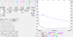
Above is a SimNEC design model, calibrated against measured input impedance with the nominal load.

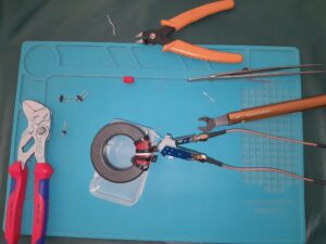
Above is a pic of the measurement setup, a NanoVNA-H4 is to the right of the equipment shown. Note that the NanoVNA does not correct Port 2 mismatch error.

The transformers are described at Conversion of NOELEC style balun board to 1:1. The setup was SOLIT calibrated, the reference plane was the output side of the grey terminal blocks.

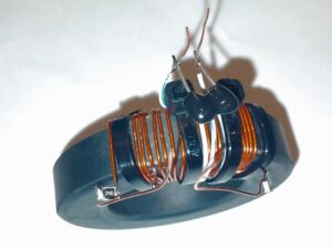
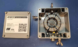
Above is a close up view of the prototype transformer with compensation capacitor. The loads are two 1% 2400Ω in parallel making 1200Ω, one in each secondary leg.

Measurement of the transformer was saved as a .s2p file.

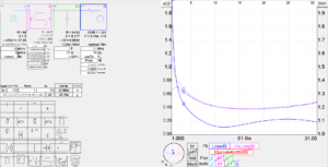
Above is a SimNEC model importing the s2p file and adjusting for the voltage division of the 2400Ω and Port 2 impedance (assumed 50Ω, but uncorrected). The indicated Loss is just a little higher than predicted by the model, keep in mind that ferrites have quite wide tolerances.

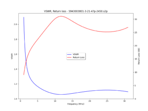
Above is a plot of measured ReturnLoss and InsertionVSWR from the .s2p file.

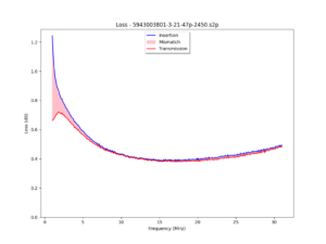
Above is a plot of measured InsertionLoss from the .s2p file, and its components Loss and MismatchLoss. See Measurement of various loss quantities with a VNA for discussion of loss terms.

Common mode impedance

Mention was made that the common mode impedance may help to reduce common mode current at lower frequencies. Zcm will look like a small capacitance below 10MHz, of the order of 10pF for the layout shown. For that reason, I would not deploy an inductive common mode choke near to the transformer, put it at the other end of the feed line.

Conclusions

This is simply an experimental prototype, it is not presented as an optimal design, but rather an indication of what might be achieved if one approaches the problem with an open mind instead of simply copying a popular design.

The revised transformer has substantially better performance than the original: ARRL EFHW (hfkits.com) antenna kit transformer – measurement .

The modifications are mainly about:

  • sufficient magnetising impedance; and
  • reducing leakage inductance.

Loss remains a little higher than I would, an opportunity for the reader to find further improvement, a learning opportunity!

Last update: 15th September, 2024, 11:30 AM

Morning on the Trail and On the Air: A Relaxing K2 QRP POTA Activation from the Campsite

I woke up around 6:45 on Saturday, August 24, 2024. That’s late for me, but I tend to sleep well when camping and it must have helped that the previous evening POTA activation by the campfire was pure bliss. There were some noises in the campground that woke me up during the night (probably other … Continue reading Morning on the Trail and On the Air: A Relaxing K2 QRP POTA Activation from the Campsite

ARRL EFHW (hfkits.com) antenna kit transformer – measurement

Two previous articles were desk studies of the the ARRL EFHW kit transformer, apparently made by hfkits.com:

This article documents a build and bench measurement of the component transformer’s performance, but keep in mind that the end objective is an antenna SYSTEM and this is but a component of the system, a first step in understanding the system, particularly losses.

The prototype

Albert, KK7XO, purchased one of these kits from ARRL about 2021, and not satisfied with its performance, set about making some bench measurement of the transformer component.

Above is Albert’s build of the transformer.

The kit parts list is as follows:

Magnetics

The first point to note is that Amidon’s 43 product of recent years has published characteristics that are a copy of National Magnetics Group H material (though they changed the letterhead).

Above is a side by side comparison of the NMG H material datasheet and Amidon 43, the Amidon appears to be a Photoshop treatment of the NMG.

Fair-rite have been a long term manufacturer of a material they designate 43 (which has changed over time), and it has been resold as such by many sellers. NMG H material is somewhat similar, but to imply it is equivalent to Fair-rite 43 might be a reach.

Overall design

I might note at the offset that the design is not original, there are countless articles on the net describing a 2:14 turn on a ‘FT240-43’ transformer for an EFHW using exactly the same winding layout.  As discussed in other articles on this site, 2t is insufficient for operation down to 3.5MHz using Fair-rite #43, even worse for the National Magnetics H material published as Amidon 43.

Measurement

Measurements were made with a NanoVNA-H4. It is not a laboratory grade instrument, but well capable of qualifying this design and build.

Albert performed a two port measurement using the setup above. This places a nominal load on the transformer, and the voltage division of the series resistor and Port 2 input impedance is used to correct the measured s21 figure.

So let’s take the measurements and calibrate a SimNEC model of the transformer.

Above is the model using Fair-rite #43 material calibrated to measured leakage inductance and InsertionVSWR. The reconciliation of model (magenta) with measurement (green) is good. The equivalent Fair-rite part is 5943003801.

Let’s compare measurement to the same model but with Amidon 43 material (NMG-H):

Reconciliation is very poor at lower frequencies, the measured transformer appears to have significantly higher permeability.

Measure core complex permeability

Let’s take a diversion for a moment and put this question to bed.

Above is complex permeability calculated from measurement of a 1t winding on the core used above compared with the Fair-rite #43 2020 published data. Keep in mind that tolerances on ferrite are relatively wide, these two reconcile very very well, there is no doubt in my mind that the material is Fair-rite #43. This questions the seller’s specified parts list.

A similar plot against NMG-H shows a stark difference.

InsertionVSWR and ReturnLoss

So let’s return to the saved .s2p file from the two port measurement.

Above is a plot of bench measurement of ReturnLoss and (related) InsertionVSWR for the transformer with a nominal load.

The InsertionVSWR might look acceptable, but using InsertionVSWR as a single metric is a very limited view.

Above is a plot of InsertionLoss (-|s21|dB), and its components MismatchLoss and (Transmission) Loss. See Measurement of various loss quantities with a VNA for discussion of Loss terms.

Let’s dismiss performance below 7MHz, the plot shows it has insufficient turns.

Importantly, (Transmission) Loss is around 1dB at 7MHz, so 20% of the input power is converted to heat in the core and winding, mostly in the core. If you look back to the first SimNEC screenshot, the model predicts just under 1dB Loss, so measurement reconciles well with the prediction model.

Experience and measurement of Loss and thermographs informs that a transformer of this type in this type of enclosure is not capable of more than about 10W of continuous dissipation in typical deployments, less if it is in direct sun in a hot climate. That means the transformer is not likely to withstand more than about 50W average input power without damage or performance degradation.

Now that might be quite acceptable to some users, gauging by the number of web articles and Youtube videos recommending this, a lot of users apparently.

Credit

Credit to Albert for his interest in understanding these things, careful measurement of the prototype, and preparedness to dismantle the prototype for science.

Summary

So let’s end this article with the results of desk study and measurement:

  • though the kit specifications state the core is Amidon #43, the sample kit is almost certain to contain a Fair-rite 43 core which is significantly different;
  • two port measurement of the sample of one with nominal load showed around 1dB of Loss at 7MHz;
  • MismatchLoss grows rapidly as frequency is reduced below 7MHz suggesting it has insufficient magnetising impedance, a result of insufficient turns;
  • the winding configuration is not optimised for leakage inductance;
  • popularity is not a good indicator of performance.

Where to from here?

These problems beg a redesign and measure of the transformer… more to follow.

Last update: 7th September, 2024, 6:19 AM

Testing My C6 Rooftop Tent During an Overnight POTA Camping Trip!

Friday, August 23, 2024, was packed with activities, but I was looking forward to the evening to wind down and relax. That morning and afternoon, my wife and I ran numerous errands around town. I played chauffeur to my daughters, taking them to their volunteer jobs and Shakespeare classes. The day wrapped up around 5:00 … Continue reading Testing My C6 Rooftop Tent During an Overnight POTA Camping Trip!

CY9C DXPedition (in the log)

Well according to their QRZ page the CY9C DXPedition to St Paul Island is now underway. The operation started on August 26th and will finish on September 5th 2024.

Here is a link to their website for those of you who want more info…

I saw them spotted on the cluster (20m CW working split) and decided to give it a try. Carefully set up the split wanted (I went up 4) and then confirmed that my trusty decoder could easily decode their CW (sent at 35wpm???)

I set my contest keyer in my Yaesu FT991a at 30wpm and then hit memory 1 on the keyer. NO Luck…. after about 3 minutes of sending my call out I finally heard back VA3QV 5nn.

I glanced at the screen to confirm what I had heard and also quickly hit memory 2 and 5nn ON was sent out. Right after that I heard TU and the screen again confirmed what I had heard…

Just for giggles I checked the Club Log for CY9C and to my surprise I found the following:

Gotta love it when a DXPedition promptly uploads their logs….

Now to be honest St Pauls Island is not exactly “rare DX” at a distance of just over 800 miles I know that I will get them on one of the bands…

Todays attempt was just quicker than I expected and in a different mode.

This afternoon (1500 utc) CY9C was spotted on 15m CW and I thought I would try again as I needed CY9 on 15m for my feeble attempts at 5 band DXCC.

It was a ZOO between the lids who can’t understand what “UP” means and the DX Cops who insist on explaining to the lid what UP means there was no chance of me hearing the reply if they actually heard me (I was up 4-8) …

Well I got a few days but at least I got them once.

73bob

Finding Joy in the Journey: A Missed SOTA Hike Leads to a Relaxing POTA Activation

On Wednesday, August 7, 2024, I planned to drive to Hickory, NC to spend part of the morning helping my father with a few tasks. I planned to stay for only three hours, leaving the afternoon open for a SOTA (Summits On The Air) activation of Bakers Mountain. Bakers Mountain is one of the most … Continue reading Finding Joy in the Journey: A Missed SOTA Hike Leads to a Relaxing POTA Activation

Thoughts on the ARRL EFHW antenna kit transformer – improvements?

This is a follow up to Thoughts on the ARRL EFHW antenna kit transformer.

The first point to note is that Amidon’s 43 product of recent years is specified identically to National Magnetics Group H material. It is significantly different to Fair-rite’s 43 mix.

Though the parts list specifies an Amidon #43 core, I note that W1VT posted recently:

The ARRL kits don’t use Amidon parts as specified in the Parts List.

That was done as a “service” to those who wanted to know where to get parts for building their own without buying the kit.

The parts are sourced by a European company and shipped as kits to ARRL HQ, which acts as the distributor.

ARRLHQ publishes a Youtube video which shows a label by hfkits.com, and their website also lists Amidon FT240-43. hfkits.com may use a ‘genuine’ Amidon FT240-43 in their kits… this article applies to ‘modern’ Amidon FT240-43.

Trusting hfkits.com and ARRL, lets take the core as a ‘modern’ Amidon FT240-43 (equivalent to NMG-H).

Estimate the power dissipated in the core magnetised to 50V applied

Let’s make a first estimate of the power dissipated in the core with 50V impressed on the nominal 50Ω input winding alone (ie no secondary winding on the core), equivalent to 50W in 50Ω.

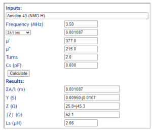
We  will calculate the magnetising admittance Gm+jBm, and the power dissipated is given by \(P=V^2G_m\).

Amidon 43 / National Magnetics H case

The first point to note is that Amidon’s 43 product of recent years is sourced from National Magnetics Group, and is their H material. It is not a good equivalent to Fair-rite’s 43 mix.

Let’s make a first estimate of core loss at 3.5MHz.

We can estimate the complex permeability which is needed for the next calculation.

The real part of Y is the magnetising conductance Gm (the inverse of the equivalent parallel resistance).

\(P_{core}=V^2G_m=50^2 \cdot 0.00950=23.8 \text{ W} \).

Amidon 43 / National Magnetics H case with 4t primary

Let’s recalculate with a 4t primary.

The real part of Y is the magnetising conductance Gm (the inverse of the equivalent parallel resistance).

\(P_{core}=V^2G_m=50^2 \cdot 0.00232=5.8 \text{ W} \).

To me, 5.8W core heating due to 50W RF input is a lot more acceptable that the 23.8W with a 2t primary. It is not stunning by an means but borderline acceptable. This configuration might stand 100W FT-8 without overheating (depending on the enclosure, environment etc).

So, can you use too many turns?

Yes, increasing the turns will increase leakage inductance which is a very important, if not most important, constraint on high end Insertion VSWR.

Try it and measure it.

Oh, but I only want to use 40m and up

You can follow the same process and estimate the minimum primary turns that suits your own acceptable core loss criteria.

Last update: 8th September, 2024, 6:13 AM

Testing the new(to me) rig

Remember yesterday when I mentioned the latest addition to my POTA setup, the Xiegu 5105 QRP rig….

Well this morning I decided to test it out and see how much work I would have to do with setting the parameters such as mic gain, processor, to make it sound like me… I was also testing out my EARCHI 9:1 unun with a 29.5 foot random wire to see how it would play with the built in AT of the 5105.

I figured I might as well do the testing at a POTA location just in case I was able to turn the test into an activation.

For this I chose Fort Frontenac POTA CA-5303. Its fairly easy to get there via the Kingston Transit system and its also close to downtown and all the amenities I might need. In the North East corner of the picture you will notice some white lines on the ground.

They are actually the walls of what’s left of that part of the Fort. Also the only parts of the Historic Site that is open to the public.

I leaned my MFJ 33 foot mast (supporting the 9:1 and wire in the vertical configuration) up against the tree.

And then ran the COAX over to the remains of the wall and set up my radio there and started operating.

My first contact was on 7.255 with the NCS of the ECARS net. He did hear me and considering I was QRP I was pleased. He did tell me that my audio seemed hot as if I was overdriving things. Lowering my voice seemed to help.

After that I looked at POTA Spots and managed to get W2IDG and VE3FI into the log from their parks and then finished up with the NCS of the MidCars net on 7.258.. All contacts were made on 40m SSB. I tried 20 SSB and was hearing lots of stations including a POTA Activation in VO1 but no luck breaking any of the pileups.

Then I figured it was time to get home and try to re configure the radio to my liking… I turned off the Speech Processor and lowered the Mic Gain from 60 to 40. Over the next few days I will get out again and see what else I have to do to get things sounding right.

Till then

73bob

Testing the new(to me) rig

Remember yesterday when I mentioned the latest addition to my POTA setup, the Xiegu 5105 QRP rig….

Well this morning I decided to test it out and see how much work I would have to do with setting the parameters such as mic gain, processor, to make it sound like me… I was also testing out my EARCHI 9:1 unun with a 29.5 foot random wire to see how it would play with the built in AT of the 5105.

I figured I might as well do the testing at a POTA location just in case I was able to turn the test into an activation.

For this I chose Fort Frontenac POTA CA-5303. Its fairly easy to get there via the Kingston Transit system and its also close to downtown and all the amenities I might need. In the North East corner of the picture you will notice some white lines on the ground.

They are actually the walls of what’s left of that part of the Fort. Also the only parts of the Historic Site that is open to the public.

I leaned my MFJ 33 foot mast (supporting the 9:1 and wire in the vertical configuration) up against the tree.

And then ran the COAX over to the remains of the wall and set up my radio there and started operating.

My first contact was on 7.255 with the NCS of the ECARS net. He did hear me and considering I was QRP I was pleased. He did tell me that my audio seemed hot as if I was overdriving things. Lowering my voice seemed to help.

After that I looked at POTA Spots and managed to get W2IDG and VE3FI into the log from their parks and then finished up with the NCS of the MidCars net on 7.258.. All contacts were made on 40m SSB. I tried 20 SSB and was hearing lots of stations including a POTA Activation in VO1 but no luck breaking any of the pileups.

Then I figured it was time to get home and try to re configure the radio to my liking… I turned off the Speech Processor and lowered the Mic Gain from 60 to 40. Over the next few days I will get out again and see what else I have to do to get things sounding right.

Till then

73bob

What was old is new again

People who know me have heard me say that after all these years there are 3 radios I have sold that I actually regret selling. Well now there are only 2 radios that I regret selling…

.

Welcome the Xiegu X5105 back into my portable shack…

.

Between my FT991a and my FT891 there was a bit of a gap. The Yeasu FT891 Portable Station was a bit too heavy for my old bones. I needed something in a lighter backpack to make it easier to carry if I was to choose to activate one of the local POTA Parks here in Kingston.

The above pic shows my old X5105 with the Bandspringer attached

The Xiegu X5105 fills that gap. With the built in battery pack, the built in automatic antenna tuner along with the contest keyer and the built in CW Decoder it makes it a dream portable station.

My antennas are a 40m EFHW made with 28ga wire and a QRP AMAZON 49:1 unun. I also can use a 29foot end fed random wire using a QRP EARCHI 9:1 unun.

I also have the SOTABeams Bandspringer antenna that plugs right into the antenna input and uses the built in tuner to operate between 10m and 60m.

So what’s the other two radios you might ask?

Above is my first QRP setup. FT817, LDG QRP Autotuner.

If I could work a deal for a Yaesu FT817 and a Flex 1500 it would complete the list. However used rigs are pricy and it seems most hams think that radios seem to appreciate with age so like I mentioned above it has to be a good deal for both the seller and myself.

73bob

Field Report: POTA Energy Boost at Tuttle Educational State Forest

Somedays, I just need a little POTA and radio-active therapy to energize the day. And this was one of those days. On Thursday, July 18, 2024, I woke up still feeling quite tired because I had been out the entire day before helping my sister with a move–my wife and I didn’t get back home … Continue reading Field Report: POTA Energy Boost at Tuttle Educational State Forest

Testing out a “Newly built” antenna

Last night around 9pm I was browsing Amazon and found the same 64:1 unun that I use with my 40m EFHW. This antenna is my primary antenna for my “Transportable/POTA” setup with my FT891.

I decided that the last one worked so well for me that it was time to see if the 1st one was the real deal or a fluke.

Around noon today I checked my front door and found the Amazon Fairy had magically made the new 64:1 unun appear sometime between 10am (last time I checked for it) and noon.

I had a spare 100 foot roll of Princess Auto 18ga insulated wire in the shack and as a bonus for my home environment is was even green.

I quickly measured out 64 feet and then did the connection things. As with most of Eastern North America it was a rather wet day.

Around 4pm locally the rain stopped and I was able to remove the old wire and install the new antenna, once again using the fir trees on the edge of my yard for camo as not draw attention to the antenna.

The SWR is pretty good especially for a wire hidden in the branches:

6m – 2.5:1, 10m – 1.7:1, 12m- 1.2:2, 15m – 1.6:1

20m – 2.0:1, 40m – 1.3:1, 80m – 3.0:1

The bands are not the best, but signal reports (90w output pwr) were fairly well (S7-S9+) with the stations that I was able to contact.

All in all for what it is…. I’m impressed and the best part is that using the built in auto tuner on my Yaesu FT991a I can easily bring it down to 1:1 on all the bands listed above.

The results are the same on my Yaesu FT891 with the same style of balun and a 64 foot length of quality (Red) Princess Auto 18 ga automotive wire. The only real difference is that as I use the 891 with no tuner I have to be careful on some of the bands.

As the new install gets more use I will let you know if there are any “issues” with its performance.

73bob

❌