Reading view

There are new articles available, click to refresh the page.

Transformers and magnetic saturation

It seems that even a basic but sound understanding of transformers challenges lots of hams, and even online experts that have been heard to brag of their qualifications so as to intimidate others who might question their words.

So at ARRL EFHW (hfkits.com) antenna kit transformer – revised design #1 – part 2 I estimated that at a current of 4Arms marked the onset of non-linear B-H response, ie the onset of saturation.

One online expert proposed a method that would rate this transformer at maximum 4^2*50=800W at which magnetic saturation would occur.

The referenced article estimated saturation at more like 17000W.

Some very basic transformer concepts

Let’s talk about some really basic transformer concepts.

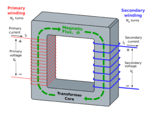
The diagram above from Wikepedia shows a rectangular magnetic core with two windings, a primary and secondary on opposite limbs of the core.

Note the phase polarity markings (+ / -) and the direction of (conventional) alternating current.

An example for discussion

Above is an example power transformer for discussion, 240V 50Hz 100VA, n=Vs/Vp=1/20, rated primary current 0.416A, core mass around 800g, estimated core loss at 1W/kg is 0.8W, for a simple explanation, leakage is assumed zero and rated load is assumed purely resistive. Note that an AC power transformer is typically rated for primary voltage, frequency and VA, and that they are operated into the low end of BH saturation, a compromise between weight, dissipation and efficiency (and cost of course).

Let’s assume that it is a good design, and for a first analysis, let’s ignore flux leakage, ie flux due to current in one winding that does not induce voltage in the other winding (does not ‘cut’ the other winding). Let’s analyse it with no load and rated load.

No load

With load load, assume zero current flows in the secondary.

The primary winding acts like an iron cored inductor, when voltage is applied, current flows. The current produces magnetic flux and a voltage induced in the primary winding which by Lenz’s law opposes the voltage that created the current.

The current that flows with no-load is known as the magnetising current, it establishes magnetic flux in the core. In a good design, the magnetising current is small wrt rated current. We can extend that and talk of the corresponding magnetising impedance and the magnetising admittance.

For the example 50Hz transformer shown, the magnitude of magnetising current is 12mA, 2.9% of rated current. Magnetising current is a component of primary current in a loaded transformer.

You might at first think that the magnetising impedance Zm is purely inductive, but that would make it lossless and nothing is lossless. In the example case, the phase of Zm is 74°, Zm=5556+j19213Ω.

Magnetising force is given by \(mmf=n(I_p +0.012 \angle -74°  – \frac{I_s}{n})=n 0.012 \angle -74° \text{At/m}\).

Rated load

So, when rated current flows in the secondary, it induces a voltage component in the primary winding that opposes the voltage induced in the primary by the magnetising current component, so more primary current flows… rated primary current in a zero leakage scenario.

Print the diagram and annotate it with a pencil, and work through Lenz’s law and the direction of current. Sure, I could have done it, but you will learn more by working through the solutions, you will remember it better, and get confidence in your growing analytical capability.

So, the primary current under rated load is the load current divided by the turns ratio, plus the magnetising current. In this example, Ip=0.416-0.012∠-74°.

Why does the core not saturate?

You need to calculate the net magnetising force by adding the primary and secondary magnetising force components. In this case, recalling that Is=Ip/n for our scenario, \(mmf=n(I_p +0.012 \angle -74°  – \frac{I_s}{n})=n 0.012 \angle -74° \text{At/m}\), the same as the no-load magnetising force.

Note that when leakage inductance and winding resistance are factored in, loaded magnetising force is usually a little less than no-load.

If load current does not cause saturation, what does?

Two common causes:

  • operating at lower that rated frequency; and
  • operating at higher than rated voltage.

Because the B-H response is non-linear, a small increase in primary voltage creates a disproportionate increase in core less (due to higher flux density).

But my guitar amp can be driven to transformer saturation!

Sure, it is being driven to higher voltage and or lower frequencies than the design point, both of which contribute to saturation. Changing the load impedance does not directly cause magnetic saturation.

My ferrite cored EFHW transformer is easily saturated!

Probably not. Naive users often incorrectly blame overheating of the ferrite core beyond the Curie point as magnetic saturation.

Conclusions

  • Lenz’s Law is key to understanding.
  • Increasing primary voltage or lowering frequency can cause magnetic saturation.
  • Increasing load current alone is unlikely to cause magnetic saturation.
  • Other non-linear behavior is often wrongly attributed to magnetic saturation.
Last update: 5th October, 2024, 5:04 PM

Fall “POTA” Event

Support Your Parks

This event happens seasonally, on the 3rd full weekend of the month (Saturday & Sunday UTC). These are ‘activity weekends’ where the main purpose is to get out in the parks, and have as much fun as possible.

  • Winter – 3rd Full Weekend of January. January 18-19, 2025
  • Spring – 3rd Full Weekend of April. April 19-20, 2025
  • Summer – 3rd Full Weekend of July. July 19-20, 2025
  • Autumn – 3rd Full Weekend of October. October 19-20, 2024

Hope to get you in my Logs during the upcoming event….

73bob

Giuseppe’s “Delicate” Loop Antenna

Many thanks to SWLing Post contributor, Giuseppe Morlè (IZ0GZW), who writes: Dear Thomas, I am Giuseppe Morlè, IZ0GZW, from Formia, located in central Italy along the Tyrrhenian Sea. I hope everything is going well for you after the hurricane and that you and your loved ones are in good health. I’m sending you this latest […]

Space Station Slow Scan TV Transmissions

2024-10-08 ARISS SSTV ExperimentARISS is planning a Slow Scan Television (SSTV) experiment from the International Space Station, scheduled to start on Tuesday, October 8, at 16:00 GMT and running until Monday, October 14, at 14:10 GMT.

There will be an interruption on Friday, October 11, for planned school contacts over Europe.

The SSTV transmissions will be made using the amateur radio station in the ISS Service Module. The transmission frequency will be 145.800 MHz FM, using SSTV mode PD120.

The ISS callsign will be RS0ISS.

Reports are requested: please send ARISS uploading your decoded pictures in the official ARISS SSTV gallery: https://www.spaceflightsoftware.com/ARISS_SSTV/

Useful information to receive the pictures can be found here: https://amsat-uk.org/beginners/iss-sstv/

Follow ARISS on X for official updates during the event https://x.com/ARISS_Intl

Space Station contact with UK Girlguides

2024-10-05 ARISS UK Girlguding ContactAmateur Radio on the International Space Station (ARISS) has received schedule confirmation for an ARISS radio contact between an astronaut aboard the International Space Station (ISS) and members of Girlguiding Surrey West County, at the Brooklands Museum and Brookland Innovation Academy, located in Weybridge, UK. ARISS conducts 60-100 of these special Amateur Radio contacts each year between students around the globe and crew members with ham radio licenses aboard the ISS.

Listen 145.800 MHz FM at 12:29 pm BST (11:29 GMT) on Saturday, October 5, or watch the livestream at https://live.ariss.org/

Girlguiding Surrey West is a charity organization for girls and young women. Girlguiding wants to inspire their members to learn skills in science, technology, engineering and math with fun guiding activities and science-based activities. The Brooklands Innovation Academy, established in 2022, creates inspirational STEM experiences for young people. The age range of the participants for this ARISS contact are 5 to 19 years old. By hosting this ARISS contact they are also demonstrating real-world application of STEM concepts (an important principle at Brooklands Museum) to space missions and are encouraging the girls to complete their space interest badge. The group is being supported by the Radio Society of Great Britain and the ARISS UK Team to establish the radio link.

Duchess of Edinburgh 2024Girlguiding patron, Her Royal Highness The Duchess of Edinburgh will attend and take part in the ARISS contact to help in promoting the engagement and involvement of girls and young women in STEM.

This will be a direct contact via Amateur Radio allowing students to ask their questions of astronaut Sunita Williams, amateur radio call sign KD5PLB. The downlink frequency for this contact is 145.800 MHz and may be heard by listeners that are within the ISS-footprint that also encompasses the relay ground station.

The amateur radio ground station for this contact is in Weybridge, UK. Amateur radio operators using call sign GB4GGB, will operate the ground station to establish and maintain the ISS connection.

The ARISS radio contact is scheduled for October 5, 2024 at 2:05:37 pm BST (Weybridge, UK) (13:05:22 UTC, 9:05 am EDT, 8:05 am CDT, 7:05 am MDT, 6:05 am PDT).

The public is invited to watch the live stream at: https://live.ariss.org/

_______________________________

As time allows, students will ask these questions:

1. Who or what inspired you to become an astronaut and what advice would you have for any of these girls here today who might want to become an astronaut?

2. Do you have any free time and if so what do you spend your time doing?

3. There are many international time zones so how does time work on the ISS?

4. If you were not an astronaut, what job would you like to have instead?

5. What things do you like to take with you to remind you of home?

6. What is the hardest part of your job?

7. How does the food and drinks do you have in space compare to foods on earth?

8. What do you miss about Earth?

9. How long have you been on the international space station?

10. What was your reaction when you found out you had been selected to fly to the ISS?

11. What stars or other things have you seen in space?

12. Is space hot or cold?

13. Does space smell of anything?

14. How do you sleep in space?

15. What is your favorite planet and why?

16. Have you done a spacewalk? If so, what was it like?

17. The spacesuits look very heavy, are they uncomfortable to wear?

18. What is it like floating in space? Have you ever lost anything from it floating away?

19. What things do you like to take with you to remind you of home?

About ARISS:

Amateur Radio on the International Space Station (ARISS) is a cooperative venture of international amateur radio societies and the space agencies that support the ISS. In the United States, sponsors are the American Radio Relay League (ARRL), Amateur Radio Digital Communications (ARDC), Radio Amateur Satellite Corporation (AMSAT), NASA’s Space Communications and Navigation program (SCaN) and the ISS National Lab—Space Station Explorers. The primary goal of ARISS is to promote exploration of science, technology, engineering, the arts, and mathematics topics. ARISS does this by organizing scheduled contacts via amateur radio between crew members aboard the ISS and students. Before and during these radio contacts, students, educators, parents, and communities take part in hands-on learning activities tied to space, space technologies, and amateur radio. For more information, see http://www.ariss.org/

Follow ARISS on X at https://x.com/ARISS_Intl

Those satellite enthusiasts thinking of getting their UK Amateur Radio licence may like to know a Free online training courses are available at hamtrain.co.uk

Radio Jeep – a M151A2 and M416 trailer

Technically this is a “G.P.” Rather than trademarked “Jeep” brand vehicle and trailer. It’s a M151A2 1/4 Ton high-mobility vehicle, or “General Purpose” vehicle (hence the GP name) and with a matching trailer. Roll back to the early 1980s and you would find me either being driven or driving myself in a similar M151A2 pulling… Continue reading Radio Jeep – a M151A2 and M416 trailer

Not as much Flexing

Got a lot of life stuff going, and haven’t been much on the radio. Not even listening. Nothing, nada… The push to pull many of my October/November chores ahead so that they are done prior to surgery next week, has taken up much of my operating & blogging time. Then their is a fair bit […]

Extra imagination on shortwave this Sunday

Hello all shortwave listeners and SWLing community, FastRadioBurst 23 here again with news of an extra transmisson this Sunday October 6th 2024. It’s a rerun of the Skybird Radio International (Instrumental special) on Shortwave Gold at 1800 hrs UTC on 3975 kHz and 6160 kHz. It’s all about the instrumental worldwide flavours so tune in […]

ARRL EFHW (hfkits.com) antenna kit transformer – revised design #1 – part 2

This article continues on from several articles that discussed the ARRL EFHW kit transformer, apparently made by hfkits.com, and the revised design at ARRL EFHW (hfkits.com) antenna kit transformer – revised design #1 – part 1.

This article presents a saturation calculation.

You will not often see saturation calcs (for reasons that will become apparent), though you will hear uninformed discussion promoting FUD (fear, uncertainty and doubt).

Lets assume that the core is capable of maximum continuous power dissipation of 10W (limited by factors like safe enclosure temperature, human safety, Curie point etc).

Now let’s estimate the magnetising current for 10W of core dissipation with 3t primary

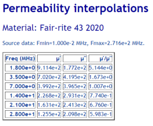
Starting with the expected permeability above…

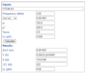
Gm is the magnetising conductance, the real part of Y above, 0.00231.

We can approximate the primary voltage for 10W core dissipation as \(V=(\frac{P}{G_m})^{0.5}=(\frac{10}{0.00231})^{0.5}=65.8V\) which implies 87W in a 50Ω load.

Magnetising current can be calculated at 10W core dissipation as \(I_m=\frac{V}{|Z|}=\frac{65.8}{222}=0.296A\)

In fact, under load, the net magnetising force may be just a little below 0.296A due to the effects of leakage inductance.

Let’s estimate saturation current for a 3t primary

Lets assume that under load, magnetising force due to current in the secondary offsets most of the magnetising force due to current in the primary and that the net magnetising force is due to magnetising current.

So, let’s solve.

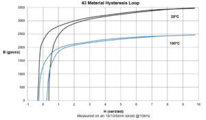
Above is Fair-rite’s published data for their #43 mix (do not assume it applies to pretenders). Let’s take saturation flux density to be 1500 gauss, 0.15T.

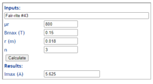
Above is a calc of the saturation current for the 3t primary (peak), 4.01 Arms.

Conclusions

The saturation current is 14 times the magnetising current at 10W core dissipation, and is unlikely to be a significant limitation for low duty cycle modes.

This EFHW transformer is loss limited rather than saturation limited for most practical applications.

If you had in mind that this transformer was suited to peak power \(14^2 \cdot 87=17000 \text{ W}\) or more, then it may be driven into saturation.

Last update: 4th October, 2024, 6:01 AM

Carlos’ Illustrated Radio Listening Report and Recording of CGTN (October 1, 2024)

Many thanks to SWLing Post contributor and noted political cartoonist, Carlos Latuff, who shares his illustrated radio listening report of a recent CGTN broadcast. Carlos notes: Part of news bulletin of CGTN Radio (China Radio International) about hurricane “Helene” destruction in Southeast US. Listened in Rio de Janeiro, Brazil. Click here to view on YouTube.

KMRT back on those airwaves of ours

Hello all shortwave listeners and SWLing community. FastRadioBurst 23 here with news of the Imaginary Stations radio shows this week. This Sunday October 6th 2024 there’s a return to the supermarket shelves with KMRT via the services of Shortwave Gold at 0900/1300 hrs UTC on 6160 kHz and then at 2000 UTC on 6160 kHz and 3975 kHz […]

Back home a week later

It was a great time being back in Ottawa, visiting with friends from my old neighborhood and also spoiling my Daughters two cats.

However on the “Radio side” of things …. not so good

The plans were that I would be able (weather permitting) continue to control my hour on the Trans Provincial Net while away. It seemed that “Mother Nature” had different ideas. Most days rain or the threat of rain kept me from heading over to the park.

Above pic showing where the park was and the route I took

As I mentioned in a previous post…. there was a local (non-POTA) park within walking distance to operate from. It was a local sports field and had some bleachers for when the crowds came for Junior Soccer/Football and or Rugby…

Below pic showing how I set up at the park

Although the operating position was excellent there was NO PROTECTION from the elements which in my case meant rain.

I was able to wrap my MFJ mast to one of the bleachers and stretch the end of the EFHW antenna to the other bleacher and it did work like a charm. Signal reports were great considering I was running 50w into the antenna

So for 1 out of a potential 5 operating days it was fun and dry. Walking home with the gear safely packed in the backpack “Mother Nature” paid a short visit.

I also managed to activate CA1515 and CA1516 using my Xiegu X5105 along with a 29 foot wire (supported by the same mast mentioned earlier) with a 9:1 unun, a 17 foot counterpoise with a choke on the radio end of the coax. Jose VA3PCJ was nice enough to offer me a ride there and back. I activated the parks using SSB and VA3PCJ activated the same parks using CW and his KX3.

For Jose’s version of the park activation click HERE

I am expecting to be returning to Ottawa in Mid-January 2025 for another visit with my GrandKits and like last years winter visit there will be a car to keep me warm and dry.

73bob

Carlos’ Illustrated Radio Listening Report and Recording of NHK (September 28, 2024)

Many thanks to SWLing Post contributor and noted political cartoonist, Carlos Latuff, who shares his radio log art of a recent NHK broadcast. Carlos notes: Part of NHK news bulletin about assassination of Hezbollah leader Hassan Nasrallah in an Israeli airstrike. Listened tonight at Prainha Beach, Arraial do Cabo, Rio de Janeiro, Brazil. This is the first time I […]

Currents at a coax to dipole junction

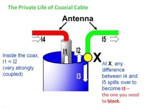
Ian White gives the following diagram to explain what goes on at the coax to dipole junction.

He labels five currents in his explanation.

Let’s simplify that

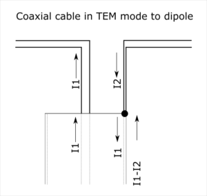
Above is a diagram from Common mode current and coaxial feed lines showing the currents where a coax connects two two wires.

Lets morph that to the dipole feedpoint topology.

The whole thing is defined by just two currents, I1 and I2. The common mode current Ic=I1-I2. There is common mode current present in the short two wire connection to the dipole, and on the outer surface of the coaxial cable.

Note that I1, I2 and Ic are usually standing waves (ie they vary with location), and so these currents are defined here at the point where the conductors meet the end of the coax.

Are the currents measurable?

Using a clamp on RF current probe, the currents on the each of the two dipole conductors I1 and I2 is measurable, and so also the current on the outside surface of the coax shield Ic.

Remember also that these are sinusoidal AC currents, and I1, I2 and Ic refer to the magnitude of the currents.

The three currents can be resolved into the common mode and differential components, see Resolve measurement of I1, I2 and I12 into Ic and Id
(I12=Ic, the current measured with the probe around both two wire conductors or around the outside of the coax.

Can the currents be measured at an elevated dipole feed point?

Sure. I have done measurements of Ic over the length of coax by hoisting a current probe on a separate halyard to raise and lower it and reading it from the ground with a spotting scope.

Recall that Ic is usually a standing wave, and when you measure it at just one point, you don’t know much about it.

Last update: 1st October, 2024, 1:46 PM
❌