Reading view

There are new articles available, click to refresh the page.

Ham Radio Tech: Inexpensive Project Enclosures

No matter what kind of operating you do, sooner or later you’ll need a “gadget” that isn’t readily available commercially.

Maybe you’ll need a special switch or an interface between connector types or to a radio accessory port. After making one or two of these, you might develop a taste for homebrewing of the electronics variety! Many hams started small and wound up making equipment that rivals professional quality.

One thing you’ll learn quickly, though, is that nice-looking metal enclosures are surprisingly expensive. Even small boxes can cost as much as the electronics inside them.

To keep the cost of building reasonable, I’ve learned to make use of less-expensive materials to make my own, particularly when building something for the first time or just trying out an idea. Low-cost materials encourage prototyping and trying out alternatives—you can then use the money saved on a better enclosure for the final version. Or you might find the inexpensive alternative to be a fine permanent solution.

Here are some tips and tricks that have served me well.

Basic Boxes

One of your most useful discoveries will be that specialty products sold for electronics are often quite a bit more expensive than a very similar product made and sold as consumer and commodity products.

This is true for more than just metal boxes!

If you can use something made and sold by the zillion, you’ll save a lot of money, especially if you are willing to accept a different shape or can modify a commercial product. For example, electric fence insulators and PVC pipe, or conduit fittings, are much cheaper than ceramic insulators!

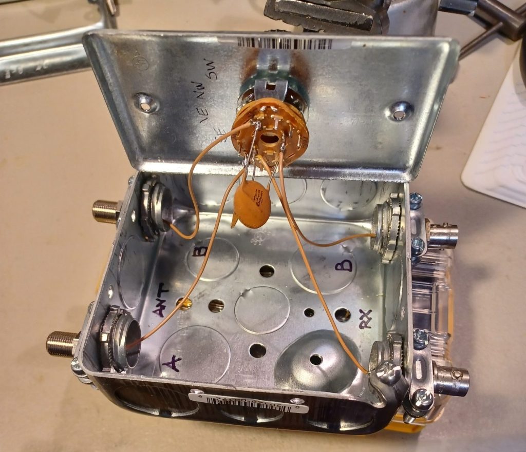
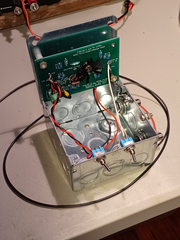
My favorite source of project enclosures is products made for electrical wiring parts, especially the junction and switch boxes. You can see several examples in the photos below. The boxes are sturdy and cheap, and they are galvanized or plated. They make good shields since they are metal, which is extra important in the ham station where RF is present everywhere.

home made Electronic button box
This photo is a great example in which I used an electrical box to make a message control box for a voice keyer. The box is a single-gang, four-inch-long, 2-1/8-inch-deep, new work utility box. (“New work” means that it’s intended for new construction.) The top is a blank cover that I drilled out for four pushbutton switches. A 3/8-inch conduit clamp secures the shielded multi-conductor cable. Total cost of all the metal parts was less than $5. (Image/Ward Silver, NØAX)

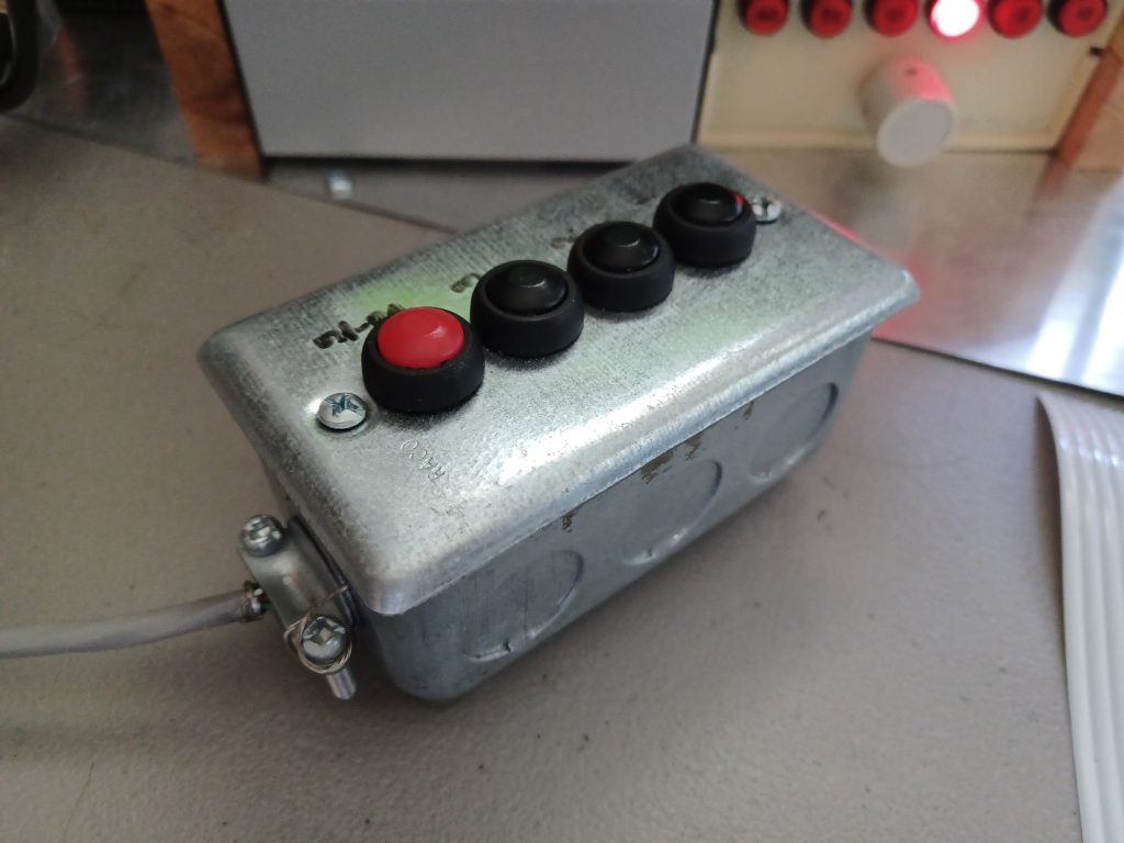
Most of these boxes have convenient holes for grounding and bonding connections. The boxes are inexpensive so if you make a mistake or decide to change a layout, you can start over very easily and cheaply. Ganged boxes can be joined together to make larger boxes. There are quite a variety of these metallic boxes available online or in the electrical section of your local hardware stores.

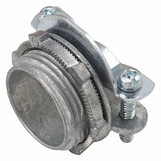
Electrical boxes have round “knockouts” for attaching conduit and cable clamps. There are three common sizes specified as “trade sizes” of 1/2, 3/4, and 1 inch. They mount in the body of the box with a small tab. Push on the knockout with a screwdriver to bend the tab, then flex it back and forth to break the knockout free. Threaded conduit clamps mount in the resulting hole. There are a large number of clamps and parts that mount in knockouts for different purposes.

Rubber grommets are available to avoid chafing a cable.

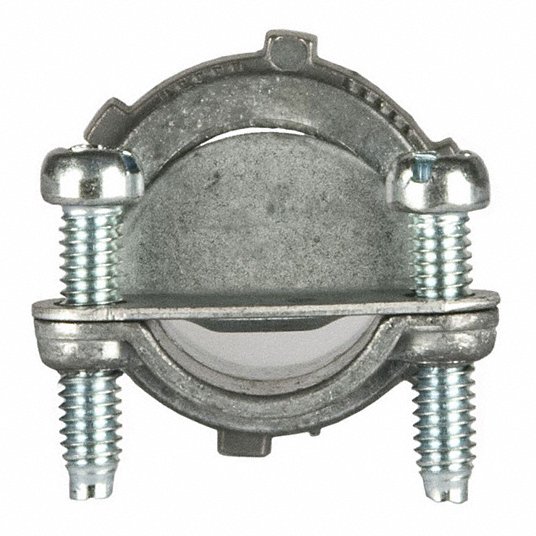
The conduit clamp is threaded and mounts on the box with a large nut similar to a toothed lockwasher. Tighten it by tapping on the nut’s serrations with a screwdriver while holding the clamp with pliers. The clamp is flat-sided to capture electrical cable and is tightened with screws. The clamp will also capture the flat side that is present on most threaded RF connectors. 

electronic box ferrule connector, side
(Image/Ward Silver, NØAX)
electronic box ferrule connector, front
(Image/Ward Silver, NØAX)

Smaller connectors, such as phono or phone plugs, will probably require a drilled hole or you can enlarge a pre-drilled hole. Another option is to use a pair of large flat washers to both fill the hole and hold a threaded connector.

If you are running coax or other shielded cable through the clamp, create a pigtail from the shield braid or wire that is long enough to wrap around one of the clamp screws. This allows you to make a good connection to the metal box.

Another nice thing about electrical boxes is that they are heavier than a similarly-sized aluminum or plastic box. This helps keep them in place when cables are attached or if controls or switches mounted on them are used frequently. Rubber or plastic stick-on feet work as well on steel as on aluminum, but be sure to clean the surface first since there may be some lubricating residue left from the manufacturing process.

homemade electronic antenna box
This photo shows a four-inch square box used to switch DC control signals to a receiving antenna controller. (Image/Ward Silver, NØAX)
antenna components in a homemade electrical box
Here’s my latest project, a preamp for Beverage antennas mounted in a four-inch box. The PCB is mounted on the enclosure’s cover. Switches fit in pre-drilled holes that were enlarged with a drill. In this photo, you can see the dual-size knockouts that accommodate two sizes of conduit clamps. (Image/Ward Silver, NØAX)

Noise Pickup

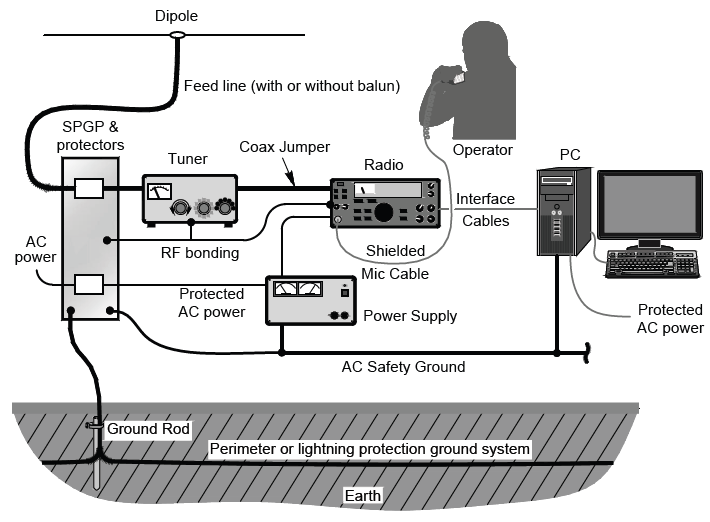
A caveat about using plastic enclosures—unshielded enclosures for RF projects can allow common-mode noise to get into feed lines. (Noise refers to any unwanted signal picked up on the outside of the shield.) Noise currents flow to the end of shield on the outside and then enter the cable as a differential-mode signal.

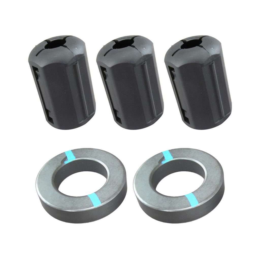
If you can’t shield the enclosure, consider feed line chokes from ferrite cores on the cables to block the noise currents.

Surplus and Used Enclosures

An often-overlooked source of project materials is surplus, overstock, or used equipment. Popular online auction websites are a good place to find enclosures and other materials. Local sources include Craigslist and free “buy nothing” sites organized by location. You will also be able to find “service pulls,” which are equipment and devices designated as past their service life. You may have to buy several to get the best price, so share the savings with friends!

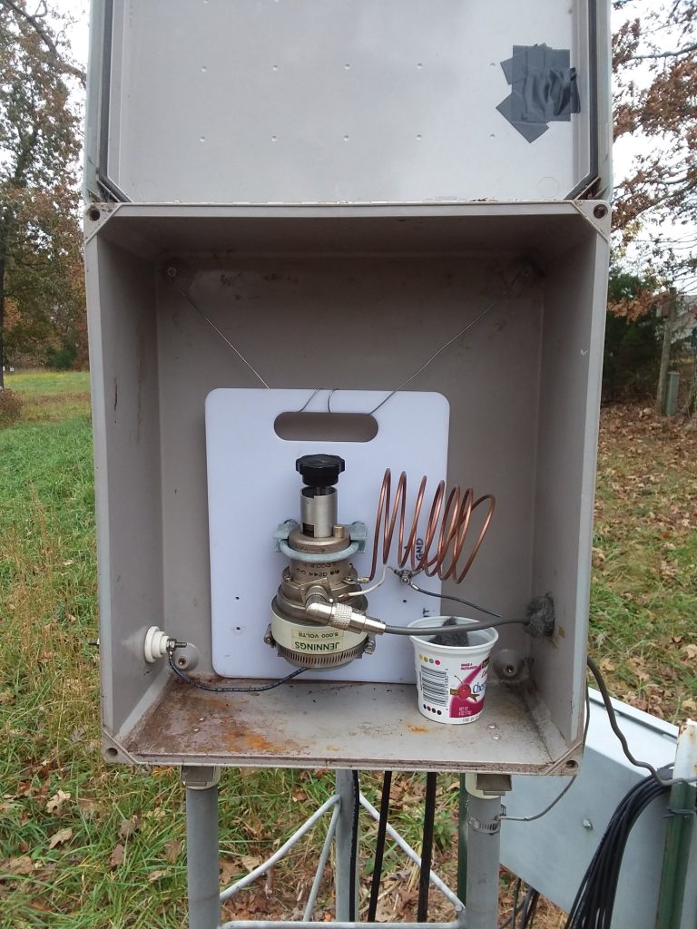
Along with hamfests, flea markets, and garage sales often include electronic gear that can be stripped for parts and hardware, with the enclosure left to be reused. Equipment cabinets for outdoor use, like the fiberglass box I bought surplus, are usually weatherproof, too.

outdoor ham radio antenna enclosure
I reused this surplus fiberglass enclosure to hold an L-network to match my tower’s base impedance on 80 meters. I used a plastic cutting board to mount the vacuum variable capacitor. Another such enclosure in the background holds a remote coax switch and lightning protection components. The yogurt cup holds mothballs to discourage critters from trying to nest inside! (Image/Ward Silver, NØAX)

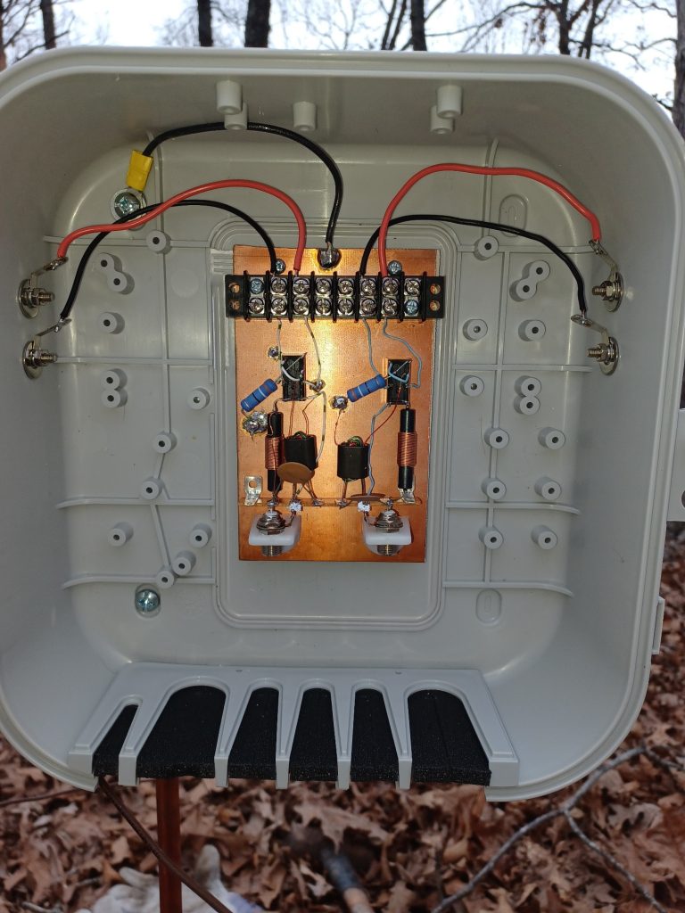
Data and cable TV service boxes are widely available as surplus and usually have a basic weather-resistant cable entry. They are mostly plastic and unshielded but make good protective enclosures for cable connections and smaller devices.

The photo below shows such an enclosure used to hold a control circuit for switching a pair of receiving loops. Feed lines come in through the foam inserts at the bottom.

outdoor electrical enclosure box with door open
(Image/Ward Silver, NØAX)

Obsolete instruments and equipment are usually constructed with solid, high-quality cabinets that cost a lot new. Panels and other metal parts can be cleaned in the dishwasher. Disassembling this type of equipment is an education in how electronic devices are assembled and provides a lot of useful hardware.

Taking this stuff apart is a great project for beginning electronics and ham radio hobbyists to build expertise (and a junk box)!

Holes in used enclosures can be filled with metal “hole plugs” that snap in place. Large holes can be covered with a piece of unetched PC board material or scrap sheet metal to maintain shielding. Older outdoor enclosures, particularly fiberglass or plastic, should be painted with automotive primer to protect and seal the surface.

Food and Novelty Containers

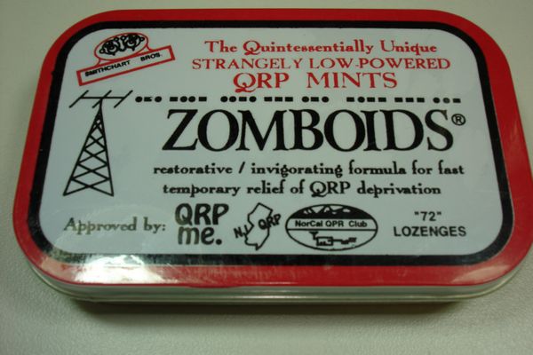
A popular activity in the QRP community is to build gadgets in the snap-together tins that hold Altoid mints. After all, they say, if the mints themselves were “curiously strong,” then why not the signal from a transmitter built in the same container?

There are even prototyping kits based on the tins such as this product from QRPme.com.

QRP Ham radio built into an altoids tin
(Image/Ward Silver, NØAX)

Don’t expect heavy-duty use from these lightweight, nearly disposable items. They are often painted and need to be scraped or sanded to bare metal around connectors and any overlap joints you expect to act as shielding. There are a variety of sizes from postage stamp-sized to large cookie and chip tins. The metal is quite thin, so drill with caution or use a punch to avoid tearing the metal. People have come up with all kinds of projects for candy tins, such as this Instructables collection.

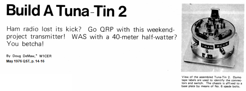
Not only candy tins are pressed into ham service. Even tuna fish cans get into the act, like the legendary “Tuna-Tin 2” 40 meter transmitter. You can read all about this Doug DeMaw, W1CER, creation from 1976 at DIYRadio. Cans make great sub-enclosures in larger projects, too.

Tuna Tin Kit screengrab
(Image/DIYRadio)

Hobbies and Crafts

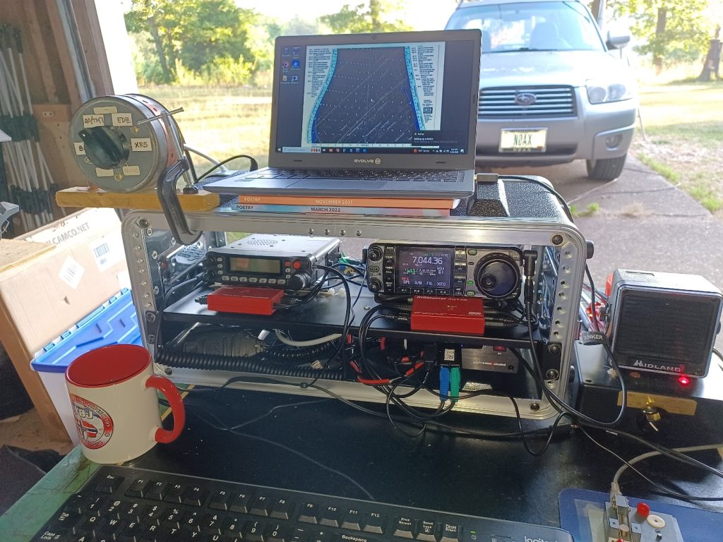
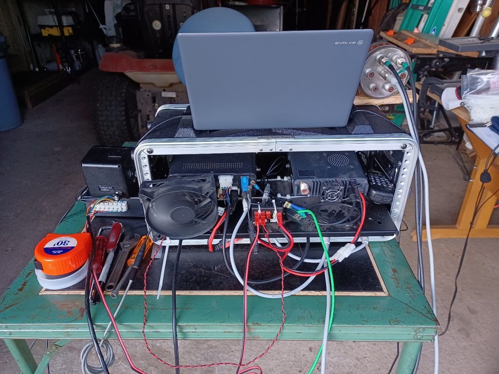
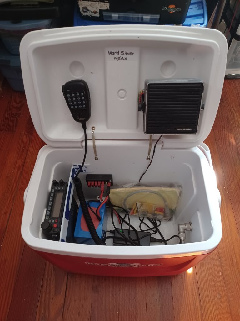
Finally, hobby, outdoor, and craft stores sell a wide variety of containers and boxes that can be used for electronics. Metal toolboxes make very nice enclosures for electronics, particularly portable or mobile radios, and can even serve as a ground plane for a mag-mount whip! They are often lockable as a bonus. Larger coolers can carry an entire station, may have wheels, and are almost always water-resistant.

My VHF/UHF emergency communications station in the photo below was built in one such cooler. Watch for seasonal sales at the start of camping, fishing, hunting, and boating seasons.

portable ham radio station built into a cooler
(Image/Ward Silver, NØAX)

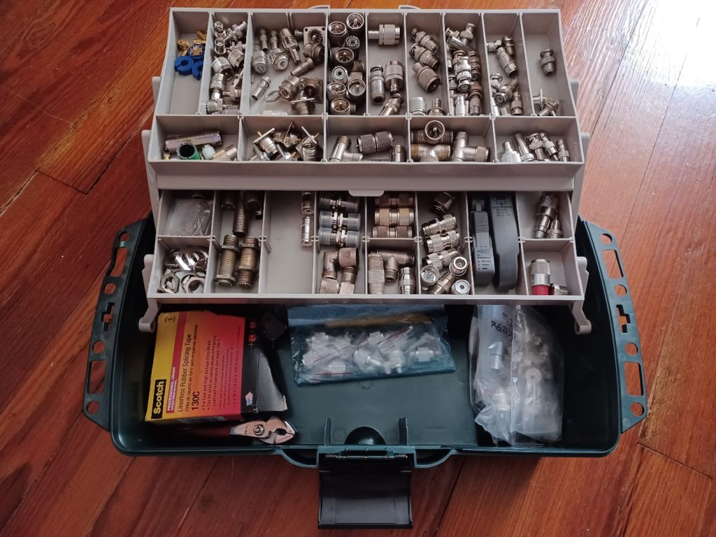
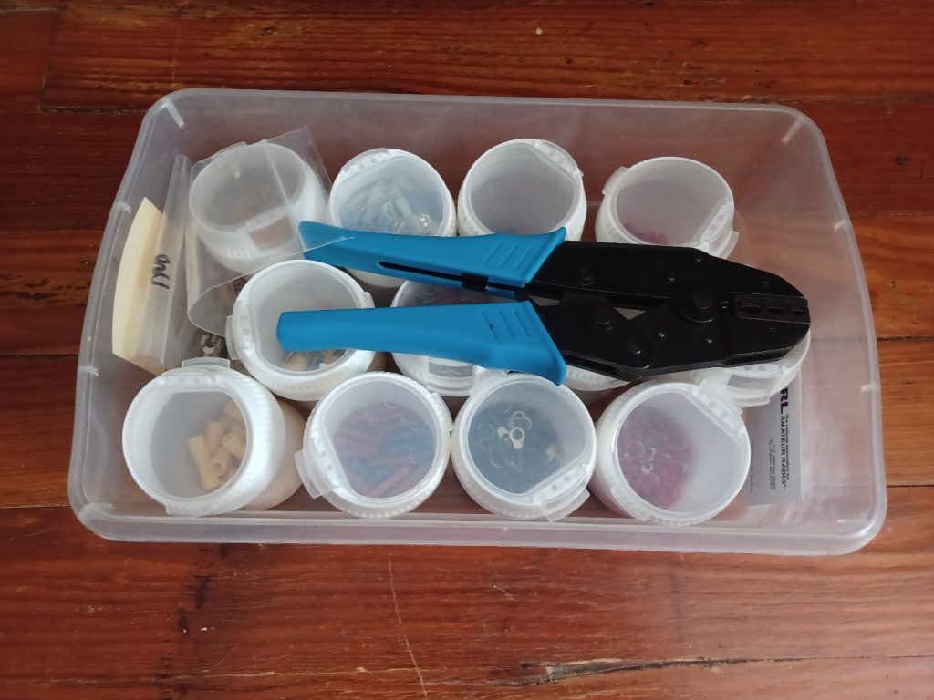
Although they aren’t often used for projects, tackle boxes, compartmented trays, and storage boxes come in very handy.

These can be used to keep connectors, parts, and hardware organized and ready for action in the field. I save my chewing gum and peanut butter jars to make great hardware kits, even including a crimping tool with the terminals so everything is kept together and sorted.

tackle box filled with electrical parts
(Image/Ward Silver, NØAX)
wire crimper tool kit
(Image/Ward Silver, NØAX)

The Eye of the Beholder

I hope this article gives you the idea that useful materials are all around—not only for enclosures, but for hardware and accessories, too. Using inexpensive materials lowers the “barrier to entry” for building your own gear and will make you a more capable and flexible homebrewer.

Editor’s note: For those less inclined to homebrew enclosures, you’ll find the DX Engineering Utility Enclosure Kit at DXEngineering.com. Check out this article on ways customers have put the DXE-UE-2P Utility Enclosure to work around their stations.

The post Ham Radio Tech: Inexpensive Project Enclosures appeared first on OnAllBands.

Ham Radio Tech: RF Safety—In the Field

This is the second installment of a two-part article about RF when you are operating “in the field,” meaning away from a fixed station.

For example, when you are operating a portable station for Parks On The Air (POTA), that’s considered “in the field” whether you are in an actual field or a parking lot or not even outside. Field Day certainly qualifies in most cases. In both parts of this article, the RF from your transmitted signal is what we’re concerned with.

Mechanical Concerns

We can start with some non-RF considerations that are certainly related to antennas, but not the radiated RF.

Most antennas used in the field are either ground-mounted or lower in height than at a fixed station. This, combined with the likelihood of their being in a public space, presents a variety of hazards to passers-by and other visitors. Your goal is to keep people from walking into, tripping over, touching, or otherwise getting too close to the antennas and feed lines.

The photo below shows a typical portable station with a table, tarp, and temporary antenna about 20 feet away in the background.

ham radio operator at a station under a tent
Carl, AE0CJ, and I operated from the grounds of Missouri’s first capitol to celebrate the state’s bicentennial. Note that the tripod-mounted antenna takes advantage of the property fence to help keep other visitors from getting too close. Below is another photo of the antenna. (Image/Ward Silver, NØAX)
portable antenna set up in a backyard
(Image/Ward Silver, NØAX)

You can see the yellow rope placed around the antenna as a warning not to get too close. Plastic fence posts were used to hold the rope. Yellow caution tape is inexpensive and even more visible. Remember that many parks prohibit sticking anything in the ground, even for safety. In such cases, orange traffic cones are a good compromise.

Feed lines and power cords present a tripping hazard to both visitors and operators. If allowed, a stake in the ground next to the cables with a bit of yellow caution tape marks their location and can secure the cables. I always tie or secure the cables to a table leg so that if something does happen, the equipment is not dragged off onto the ground. (Don’t ask me how I learned to do this…)

Finally, don’t install your antenna where it can come in contact with vegetation. The end of an antenna element can present fairly high RF voltages, even at 100 watts output. This is enough to heat up leaves to the point where they will catch fire or at least smolder. Starting a fire is a definite no-no! (Don’t ask me how I learned this, either…)

Choose Your Words Carefully

Before we go any further, I need to remind you that the word “radiation” when referring to our transmitted RF may be accurate, but it is not a word the public or facility staff are comfortable with. I am careful to keep things simple and speak of “radio signals” instead of “field strength” or “radiation.” If someone asks about risks, you could truthfully tell them they might get a slight shock if they touch the antenna while you are transmitting. (If you are using an amplifier, it might be harsher than “slight,” so consider the possibilities.) Then explain that is why you have taken steps to prevent anyone from accidentally coming in contact with the antenna.

This is also a reminder to read or re-read the paragraph on preventing RF burns in the first part of this article, “RF Management—In the Field.”

RF Field Strength

The primary concern of this article is the high RF field strength near an antenna. FCC rules require us to evaluate the RF exposure from our fixed station antennas. Portable stations don’t require the same level of scrutiny, but you can use the same methods to determine whether your portable antennas might present a hazard to you or the public with respect to the Maximum Permissible Exposure (MPE).

Uncontrolled vs. Controlled

The allowed exposure levels are different for two kinds of environments—controlled (or operational) and uncontrolled (or general public). For a fixed station at our home, for example, the antennas are on private property and access to them is limited by property boundaries, fences, etc. This implies that anyone in the vicinity of the antenna either knows it is present or is there with your permission and supervision.

This is a controlled environment, and the MPE levels are higher because it is assumed the person can either take steps to stay away from the antenna or avoid being close to the antenna when the station is transmitting.

Uncontrolled environments are different and assume someone near the antenna is not aware of what it is or that it is present. They may approach the antenna at any time and are not assumed to be under your supervision, nor can they manage their own exposure.

For example, a vehicle-mounted antenna on your car in a parking lot can be approached by anyone in the lot. This is why the MPE levels are lower for uncontrolled environments. It’s safest that you assume these limits apply when considering how to construct and use your station.

High-Q Antennas

Another factor to consider is how your antenna radiates a signal and whether the RF field strength near the antenna will be particularly strong. The antenna’s ratio of stored energy to radiated energy is a measure of the antenna’s Q. Q is also known as quality factor, and for components, measures the ratio of reactance which stores energy to resistance which dissipates energy.

Antennas that store a lot of energy in the near field (within a wavelength or two of the signal frequency) can build up a surprisingly high field strength for any given power. These are known as high-Q antennas.

A high-Q antenna usually has a very low radiation resistance, which represents the antenna’s ability to radiate power into its far field, which is what launches our signals. The low radiation resistance means the antenna has to store a lot of energy for our transmitter output power to be turned into radiated signal (or heating in antenna system losses).

Imagine our antenna as a balloon being inflated by a compressor that delivers a continuous flow of air—this is our transmitter. The antenna’s radiation resistance is represented by a hole in the balloon through which air leaks out to the outside world (i.e., our transmitted signal). The balloon inflates until the amount of air leaking through hole balances the compressor’s output. The smaller the hole (the lower the radiation resistance), the higher the pressure in the balloon must be (the near field strength) for the leaking air to equal the incoming air.

The relationship between stored energy and radiated power and Q is clearly presented in a February 2013 QST article, “Q and the Energy Stored Around Antennas,” by Kai Siwiak, KE4PT. In the article, he describes and illustrates these important relationships and gives examples for real-world antennas.

For example, dipole antennas have a Q ranging from around 7 to 20, while small HF transmitting loops (a.k.a., a “magnetic” loop) can have a Q as high as 1,000. Antennas that are physically small compared to the transmitted signal wavelength generally have low radiation resistances and are high-Q. 

You can tell if you have a high-Q antenna if the SWR bandwidth of the antenna is low compared to a full-size antenna. Along with the small loops, this includes popular antennas like loaded whips that are often mounted near the ground.

Tune the antenna for an SWR of 1:1 at the operating frequency. Then find the two frequencies at which SWR increases to 2.6, FU and FL. Divide the square root of FU x FL by the SWR bandwidth, FU – FL, and that will give you Q.

For example, if SWR equals 2.6 at 14.275 and 14.295 MHz, Q = 714. That’s a high-Q antenna!

Bear in mind that losses in the feed line will make SWR look a little better at the meter than it is at the antenna terminals, so the actual SWR bandwidth is smaller and Q is higher.

How Safe is Safe?

Like most questions about antenna systems, the answer always seems to begin with “It depends…” So do answers about minimum safe distances for transmitting antennas.

The answer depends on operating frequency, antenna Q, and transmitter output power. Since every portable setup is a little (or a lot) different, you can’t be modeling or making complex calculations all the time.

To help amateurs deal with this complexity, the ARRL provides an online RF exposure calculator.

The following is a calculation for a 100-watt, 14 MHz station using unprocessed SSB with a 20% operating duty cycle and a ground-plane antenna with 1 dBi of gain.

ARRL RF Calculator landing page screen shot
(Image/ARRL.com)
ARRL RF Calculator Screenshot
(Image/ARRL.com)

Note that it’s safe to get pretty close to the antenna. However, if I turn on speech processing or operate more aggressively, such as during a contest or POTA activation, the minimum distance will increase. Similarly, using a mode like FT8, which has a 50% duty cycle of full power on periods, will increase minimum distances still further.

This short table is an excerpt from Table 5.7 of RF Exposure and You (see this article’s conclusion for how to obtain that book) that provides typical gains for some popular portable antennas. For a vertical dipole or end-fed half-wave antenna, use the half-wavelength dipole gain. For a “hex” beam, use the two-element Yagi gain. Loaded whips are less efficient than a full-size vertical, so that antenna’s safe distances are a conservative estimate for the whip.

Typical Antenna Gains in Free Space (dBi)

  • Quarter-wave ground plane – 1.0
  • Half-wavelength dipole – 2.15
  • 2-element Yagi – 6.0

For the special case of a small HF transmitting loop, the minimum distances are larger, due to the higher stored energy of this very high-Q antenna. Siwiak calculates these minimum safe distances in his May 2017 QST Technical Correspondence item, “RF Exposure Compliance Distances for Transmitting Loops, and Transmitting Loop Current.” 

From that article, for a one-meter-diameter loop with five watts of continuous transmit power on the 40–10 meter bands, the minimum safe distance for the uncontrolled environment is 1.7 meters (5.6 feet). This increases to 2.1 meters (6.9 feet) at 10 watts output power. Table 17 from the FCC OET Bulletin 65B shows the safe uncontrolled distances for 150 watts increasing from 2.8 meters (9.2 feet) on the 40 meter band to 4.2 meters (13.8 feet) on 10 meters. 

Using an amplifier, such as for a special event or contest, with a small loop increases the minimum distances on 40 through 10 meters to 17.4 feet to 42.4 feet, respectively. (A two-meter-diameter loop on 80 meters requires 21.6 feet of separation at full power.) 

See Siwiak’s March 2012 QST Technical Correspondence article, “An Antenna Idea for Antenna-Restricted Communities” for more information.

Please Think About RF Safety

It’s easy to overlook these concerns in the “heat of battle” when you are just trying to get a station put together and on the air. Hopefully, this article will encourage you to consider antenna placement in the field. I see far too many pictures of portable setups where the antenna is a few feet away from a 100-watt transceiver. There are even photos of “mag loops” sitting right on a picnic table next to the operator! Don’t do that.

You can learn a lot more on the ARRL’s RF Exposure website. The excellent text reference RF Exposure and You by the ARRL’s Ed Hare, W1RFI, is downloadable at no cost as a PDF book. It has many helpful tables and examples.

I don’t think RF exposure is something we should be afraid of, but neither should we be careless in how we treat it.

The post Ham Radio Tech: RF Safety—In the Field appeared first on OnAllBands.

Ham Radio Tech: RF Management–In the Field

This is the first of a two-part article about RF when you are operating “in the field,” meaning away from a fixed station.

For example, when you are operating a portable station for Parks On The Air (POTA), that’s considered “in the field” whether you are in an actual field or a parking lot or not even outside. Field Day certainly qualifies in most cases.

Because these are temporary situations, you have to apply a different set of techniques to get everything working and keep it working.

“RF Management”–What Does That Mean?

In both parts of this article, I’ll consider the RF to be from your transmitted signal. There is certainly RF floating around from other signals, and some might be very strong, but let’s deal with your transmitted signal here.

What does the “management” part mean, though?

I have been using the term to include all of the various techniques that are used to keep our RF where it belongs and out of where it doesn’t belong. That includes configuring your station so that it performs correctly when you are transmitting. So, we are going “manage” how your station performs when the strong RF is present.

As you’ll see, that covers a surprisingly wide range of concerns.

Where Is the RF? 

Better to ask, Where isn’t the RF? That is really a better question than the first part.

We tend to think of our station as “over here” and the antenna radiating RF as “over there,” so the RF just flies away in the direction of other stations. Well, not quite. You, the operator, and your station are very, very close to where that strong RF is launched, at least electrically.

Let’s ask a question: What is the wavelength of a 40 meter signal?

Not a trick question! It’s about 40 meters, which is about 132 feet. More specifically, a 7.15 MHz signal has a wavelength of about 42 meters, which is about 137 feet.

Note that only two of the HF bands contain the wavelength by which they’re known: 160 meters at 1.875 MHz and 80 meters at 3.75 MHz.

If your 40 meter antenna is closer to you than about 1/2 wavelength, or 60-something feet, you’re right in the near field of the antenna! It takes another 100 feet or more to get you out of the strong RF field.

The resulting strength of your signal is going to be STRONG!

rf grounding diagram for a ham radio station
In your station, fixed or portable, everything acts as an antenna! (Graphic from Grounding & Bonding for the Radio Amateur, 2nd Edition, courtesy of the ARRL)

As a result, RF is going to be picked up by just about every bit of conductive material within 100 feet or more of the antenna. Pro tip—you are conductive as well.

Everything in your station—everything—is going to have RF voltage and RF current on it. Unless you are operating in a metal shipping container, you might as well figure out how to deal with RF.

Let’s start with your station equipment.

RF and the Equipment Table—Bonding

Take a look at your typical portable setup. There will be a radio, power supply, maybe an antenna tuner, a laptop or tablet for logging and digital modes, headphones or other audio gear, and a gadget or two. All of these are connected together with short antennas…er…wires and cables.

If you just throw everything on the table and hook it all up, there are lots of paths for RF to follow. Some might be low impedance so the RF current is high, and some might be high impedance so the RF voltage is high. The end of any unconnected wire or cable will be a high impedance point and that’s where you get an “RF burn”—on microphones, keys, and isolated metal boxes. You never forget an RF burn on your lips from touching a “hot” metal microphone!

These aren’t particularly hazardous, but they are obnoxious!

Even more obnoxious is equipment misbehaving when you press the key or mike switch. Maybe an automatic tuner decides to suddenly re-tune, a computer keyboard freezes up, or a radio changes a setting. This is caused by RF current getting into (or out of) something it shouldn’t. And what causes RF current to flow? RF voltage! More specifically, a difference of RF voltage between pieces of equipment.

If you can minimize the difference in voltage between pieces of equipment, you will also minimize RF current flowing between them along connecting cables.

That’s what bonding does for you.

If you look up “bonding” in an electrical dictionary, you’ll find that it is “a connection between two points to keep them at the same potential or voltage.” That’s all—no fancy implications or calculations. You just want to keep everything on the equipment table at the same voltage, and you do that by bonding them together with heavy wires or straps. The wires and straps should be short so they don’t have an appreciable impedance of their own.

In a portable setup, the easiest way to bond everything is to connect all of the equipment directly together. Have an assortment of jumper wires (#12-16 is good) or straps (flat tinned braid works well) that connect to screws on the metal enclosures. Powerpole connectors on the wires allow the equipment to be bonded however you arrange it. I recommend using green wire insulation and connector bodies, signifying a ground connection.

Another option is to put some aluminum foil under all the equipment and connect the enclosures to it with heavy test clip leads (#18 or heavier). The metal surface helps equalize voltage.

This is a great addition to any go-kit and has saved Field Day for me more than once.

The foil weighs hardly anything, so you can even use it for Summits On The Air (SOTA) stations carried in your pack. When you’re done, wad it up and recycle it. The foil surface should be big enough to cover a strip under all your equipment. I find a three-to-four-foot strip is more than adequate.

RF and the Station Wiring

What about all those cables connecting everything together? There are three basic techniques that will reduce or eliminate most RF problems:

  1. Use the shortest cables you can. One-foot USB and audio cables are available. 
  2. Coil up excess cable in a figure-8 to minimize its inductance and the RF voltage it will pick up.
  3. Use shielded cables for everything and avoid plastic, unshielded boxes for equipment enclosures.
  4. Have Type/Mix 31 (preferred) or 43 ferrite clamp-on cores available.

What is a figure-8 winding? This is a handy technique for all kinds of cable, including coax feed lines, power cables, and extension cords. The basic idea is illustrated in the last half of this YouTube video on cable winding for video work. If you practice these techniques, you’ll avoid creating a spiral twist that creates kinks. For small cables, you can wind the figure-8, then fold the two halves together. Winding half the turns in opposite directions causes a magnetic field to create equal-but-opposite voltages in the coil, minimizing RF pickup.

If you use the aluminum foil approach or have a metal table, lay the cables, including the excess length all coiled up, on the foil. That minimizes the length of cable exposed to the RF fields.

If you do need the ferrite cores, place them on the affected cable as close to the equipment experiencing interference as possible. Wind several turns of the cable onto the core before snapping it shut. Be sure both surfaces of the core are flat against each other. This creates an impedance that blocks the RF current where it is getting into the equipment.

If you’re not sure what mix makes up a “mystery core,” it’s worth buying a half dozen, then labeling or color coding them as in this photo of a ferrite core kit. The toroids can be used to wind multiple turns of coax and power cords. Snap-ons can be labeled with a permanent marker or colored tape.

ferrite chokes for a wire
(Image/DX Engineering)

A combination approach that accomplishes bonding and keeps all of your equipment together is a portable rack. These have metal shelves and rails with an overall plastic enclosure. They’re usually available as portable audio equipment racks.

You can install all of your portable equipment more or less permanently in one of these racks. This lets you bond everything, use short cables, and debug all of the wiring so that when you take the rack of gear to the field, you know it will work with a minimum amount of setup.

True, a rack is heavier and not suitable for backpacking, but for many portable vehicle-based scenarios, it will be just fine.

These photos are from my Field Day operation in 2023 showing an IC-7000 and an FT-7900 in a standard portable audio rack. All of the equipment is bonded to the metal rack shelf. The operating table is my great-Aunt Ruth’s!

front view of a portable ham radio station on a tabletop
(Image/Ward Silver, NØAX)
rear view of a portable ham radio station on a tabletop
(Image/Ward Silver, NØAX)

Despite your best efforts—and every field setup is different—you may find that transmitting on a particular band “lights up” the station equipment (or the operator). You might see RF interference to equipment, or a “hot spot” may cause a tingle (or more!) on some frequencies.

In this case, use a 1/4-wavelength piece of wire (calculate as 470/f in MHz–length is not critical) attached to the affected equipment on one end with an alligator clip and left open on the other. Insulate the open end.

This detuning wire will create a low-impedance point, lowering RF voltage where the wire is attached. The open end may have high voltages on it, so insulate it and don’t put it where you might touch it or step on it with bare feet! (Don’t ask me how I learned this…) Have one detuning wire for each band you plan on using.

RF on the Antenna System

Other than on the antennas themselves, as discussed earlier, RF is going to be picked up by every conductor in your station, including by the antenna feed lines as common-mode current. This is a particular challenge in mobile operation since the vehicle body is part of the antenna. The RF picked up by the feed line will flow into your station and cause problems unless you take steps to block it:

  1. Use a common-mode choke (ferrite or wound-coax) where the feed line attaches to station equipment.
  2. Add one or more chokes along the feed line between the station and antenna. If you are using an end-fed half-wave (EFHW) antenna, a choke at the impedance transformer may affect the antenna’s SWR. Check the antenna manual for guidance.
  3. If you are using a vertical antenna, such as a whip with a base-loading coil close to the ground, place some chicken wire or hardware cloth under the antenna to act as a ground plane. Route the feed line underneath it to maximize the shielding effect.
  4. If your antenna is mounted on a vehicle, bond the antenna mount to the body with a heavy wire as close to the mount as possible. This helps keep the feed line from becoming part of the antenna.
  5. In a vehicle, operate with the doors closed to keep RF on the outer surfaces. A ferrite choke where a feed line enters the vehicle is also helpful.

Finally, what about a ground connection to the Earth itself?

Generally, you don’t need one! Most generators do not require a ground rod or connection—check the manual.

A vertical antenna will require radials or a ground screen as in item three above but does not need a direct connection to the soil. Horizontally polarized antennas like dipoles, most EFHWs, and double-whips will be de-tuned by a ground connection. In many public places, it is not allowed to drive stakes or rods into the ground.

What about lightning protection?

In a portable or mobile setup, the best advice during storms is to lower the antennas to the ground, disconnect the feed line and secure it at least six feet from the station. There is little you can do to protect your equipment from a lightning strike in the field. Take shelter yourself! If you’re in a vehicle and lightning is striking nearby, close the doors and try not to touch any metal until the storm passes.

***

This article touched on some of the important aspects of dealing with the strong RF you’ll encounter when operating a portable station. In the next article, I’ll discuss some concerns for RF safety in these setups, an often-overlooked aspect of setting up away from home.

The post Ham Radio Tech: RF Management–In the Field appeared first on OnAllBands.

How To Strip (Wires and Cables)

Let’s start with a story about how NOT to strip wires. Back in the day, I worked with a fellow who had the unique talent of stripping wires with his teeth!

Well, just two of his teeth, actually.

It seems that at some point in his youth, he chipped the adjacent corners of his two front teeth just a little bit. The size of that little gap was just right for hookup wire, telephone wire, and all sorts of other wires. He would put the wire between his teeth, bite down just a little, and pull. Voila! Wire stripped and insulation spit out.

DON’T TRY THIS AT HOME!

Lucky for us, there are many great and inexpensive tools for getting insulation off of wires. You might only need to do that occasionally or you might need to strip dozens of wire ends. Whatever your need, there is a tool for you.

Let’s start with the most common and inexpensive manual stripper.

Basic Wire Strippers

My first order of business is to warn you about the too-cheap, no-name combo tools. While it might be nice to have one of those in the glove compartment for emergencies, they really aren’t quality workbench and toolbox tools. Good tools will last and last while doing the job right, so spend the extra few bucks on a “real” wire stripper from a solid tool company. If you need to spend a few bucks to qualify for free shipping, you could do a lot worse than to buy a good spare stripper.

Below is the Klein 1010, a basic wire stripper from Klein Tools, a well-known and trusted name in the electrical industry. As you can see, it not only strips and cuts wires from 10-22 AWG but crimps terminals, cuts small screws, bends wire, and has small plier jaws.

All of these functions are demonstrated in this handy video, “8 Wire Stripper Features Everyone Should Know.”

This is a low-maintenance tool. Keep it clean and free of rust and it will be your toolbox buddy forever.

close up of a set of wire stripper heads
(Image/DX Engineering)

Once I discovered it, I’ve used the small-screw cutter many times, making a short screw that was just right for the job. The important thing is to insert the screw so that after it’s been cut, you use the threaded part of the cutter to clean and re-align any distorted threads as you removed the screw. And sometimes, the little studs that are left can be used to join nuts or spacers.

You can tell I never throw anything away!

If you do a lot of home AC wiring, you can also find heavier strippers designed for the Romex-style cable and wire sizes you’ll encounter in those jobs. These will do a better job than the small strippers for electronic and radio work. They are also a little easier on your hands for the harder squeezing and pulling necessary for that type of work.

The pocket-friendly Squirt ES4 is a nice variation in the Leatherman line of multi-tools. Widely available used and occasionally new or in similar models, it includes a dandy little combination of wire stripper/cutter/needle-nosed pliers.

Folded up, the tool is less than two inches long. You’ll forget you’re carrying it, which is a bad thing if you try to take it through airport security! I’ve had to give up a couple of these that way, which is probably why they’re available used! Larger Leatherman multi-tools are also available with wire strippers.

folding multi tool pocket knife
(Image/DX Engineering)

Using manual strippers is pretty straightforward: insert the wire into the appropriate hole, squeeze, and pull. But there are a few fine points:

  • Be sure to use the right size hole, otherwise you’ll nick solid wire (leading it to break when bent) or cut off strands of stranded wire.
  • Using a too-large hole means you’ll get a ragged edge on the insulation and often pull the wire out of a multi-conductor cable.
  • Don’t rock the stripper back and forth because that will nick the wire. If you have to do this to get the insulation off, either you’ve used the wrong hole or the jaws are dull and the tool should be replaced.
  • Pull the wire straight through the stripper and don’t bend it, causing nicks and cutting strands.
  • If you find the stripping force pulling one wire out of a multi-conductor cable, use needle-nosed pliers to hold the wire while it’s being stripped.

Using a diagonal wire cutter as a stripper is a skill many of us old-timers have developed. Like my friend with the chipped teeth, there is a knack to doing it without damaging the wire. A gentle squeeze will put a nick in the insulation which will then break and slide off the wire. This will only work reliably on insulation that breaks cleanly and won’t leave a clean edge on the insulation. 

Automatic Strippers

Sometimes you’ll find yourself faced with having to strip many wires for a big wiring job or preparing multi-conductor cable for a rotator or control circuit.  If you are installing crimp terminals or connector pins, you need to strip all of the wires consistently and with the right length of exposed wire. This is where a self-adjusting wire stripper comes in very handy.

Properly set, these strippers will make a consistent, clean strip over and over. That results in higher quality work with better reliability.

Another item in the Klein Tools catalog, the Klein 11061 is a typical example of these tools. They don’t have all of the accessory features of the 1010 but make short and consistent (there’s that word again) work of stripping a lot of wires. After you insert the wire between the jaws, squeeze the handles—the jaws clamp the wire, and the blades come together to cut and pull off the insulation.

Here’s a video of how to use it and how they work

Klein Wire Stripping Tool
(Image/DX Engineering)

The Performance Tool W200 is a variation of the automatic strippers. It has jaws to hold the wire and a pair of cutting blades that come together and pull off the insulation. The sequence is completely automatic and the design of these tools to make this sequence happen is pretty nifty.

Wire stripping tool with red handles
(Image/DX Engineering)

Pistol-grip adjustable automatic strippers are also available, such as the Tool Aid 19100. The wire is inserted in the end of the jaws until it contacts the adjustable stop. Squeeze the jaws and the tool does the rest. This tool is intended for smaller gauge wire from 12 to 22 AWG.

I’ve used all of the different types of strippers and each has their appropriate role. I carry a manual and an automatic stripper in my tool kit. These are also fairly inexpensive and worth adding to your tool roster. You might also enjoy Adam Savage demonstrating how these work in this entertaining video.

Stripping Enameled Wire

So far, we’ve focused on wire with plastic insulation, and that is most of the jobs you’ll encounter. However, if you wind toroids or impedance transformers or baluns, it’s common to use enameled wire which is harder to strip. You want to avoid nicking the wire with a cutter or knife—it will break from mechanical or thermal flexing—so a different technique is required.

A convenient method for occasional use is to use sandpaper or emery boards. A small strip of sandpaper held between your fingers to squeeze the wire is an easy skill to learn. Squeeze the wire, rotate it, and pull it in and out of the sandpaper. This scrapes off the enamel without damaging the wire underneath.

This video shows how to do it properly.

If you have a big project with a lot of inductors or transformers, you can save yourself a lot of work (and sore hands) by using a power tool to scrape off the enamel. The Abisofix tool shown in the photo and this video will do the job on a wide range of wire sizes from 12 to 24 AWG. For very fine wires, the manual method is best for the home builder.

power wire stripping tool
(Image/DX Engineering)

Removing Heavy Insulation

A situation you’ll encounter frequently is removing the outer insulation from multi-conductor cables like rotator control or networking cable. If you don’t have a special cable stripper, you’ll have to use a knife or razor blade to remove the insulation. Be sure to use a SHARP, new blade for a utility or craft knife. A dull blade will make this job hard to do well.

  1. Score the insulation—cut the insulation but not all the way through. You can hold the cable in one hand and cut with the other, but an easier and more controlled way is to place the cable on a work surface and roll it under the blade.
  2. Do not cut into any of the inner conductors. It’s best to cut too shallowly at first, then go deeper as needed.
  3. Bend the insulation back and forth so that it breaks along the score. You may need to touch up the scoring in spots.
  4. Twist the insulation off in the same direction that the individual strands twist.

If you are working with coaxial cable, use a stripping tool for coax if possible. Those tools are well-covered in other On All Bands articles and videos.

However, sometimes you have to strip coax manually. First, when removing the outer insulation, be extra careful not to cut through the fine strands of shield braid. Take your time and work through the outer insulation. Use your sharpest wire cutters when removing the braid. Then repeat the score-and-bend technique to loosen the center insulation. 

It’s often hard to pull off coax’s solid center insulation without pulling it partially out of the braid. You can use manual wire strippers to hold the remaining insulation while pulling off the unwanted part. Carefully close the strippers on the center conductor using a stripper hole one or two wire sizes larger than the conductor so it doesn’t nick the coax conductor. Then slowly pull off the center insulation, remembering to twist the insulation in the same direction as the strands of wire.

Use the Right Tool

Just to repeat the message, use the right tool for the job and learn how to use it properly. So many problems in the ham station trace back to connectors and wires breaking or pulling loose. By doing it right the first time, you can save yourself a lot of headaches and keep ham radio fun. No matter what the type of wire or cable, there has probably been a special tool designed for it.

Many are quite inexpensive—don’t you have a birthday coming up?

The post How To Strip (Wires and Cables) appeared first on OnAllBands.

❌