Reading view

There are new articles available, click to refresh the page.

The Saltwater Amplifier Effect (& How it Impacts Your Amateur Radio Station Performance)

For Guglielmo Marconi, the great challenge was to transmit wireless signals across the Atlantic and to all the ships at sea. He built stations at Poldhu, England; Glace Bay, Nova Scotia; and Cape Cod, United States—all near the ocean.

Was this done with a knowledge of oceanside propagation, or was it because he was in the business of ship-to-shore communication?

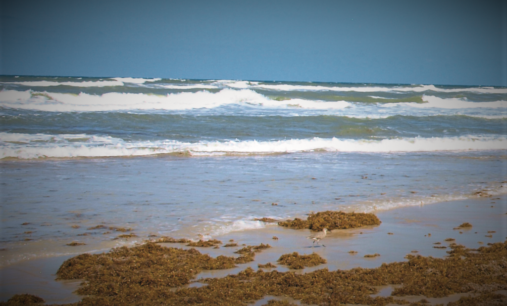
Those of us blessed with a waterfront residence on the east or west coast have much stronger communications links across the Atlantic or the Pacific than people living in the middle of the continent. We’ve all heard stories of antenna farms on or near saltwater marshes that get much improved signals. I even heard one about a ham with both feet in the Atlantic operating a low-power backpack radio with a whip and having a QSO with a station in France.

The “saltwater amplifier” is the increased ground conductivity near the sea, leading to more antenna gain. Average soil has a conductivity of 0.005 Siemens per meter, saltwater averages 5.0 Siemens per meter—an improvement by a factor of 1,000.

Do the math and that’s roughly 10 dB of gain. Imagine turning your 10-watt QRP radio into the equivalent of 100 watts.

Medium Wave Beside the Waves

Early on, some AM stations in the metro New York City area learned that oceanside towers can produce big signals. For more than four decades, High Island had been home to two of the biggest New York City AM signals: WFAN (formerly WNBC) on 660 kHz and WCBS on 880 kHz.

CBS’s station was so powerful that it could be heard as far away as Florida and Chicago on good days. Typical coverage included daytime signals up the coast as far as Cape Cod and down to Cape May. Then as now, CBS was one of America’s principal broadcasters, and the company found the saltwater ground system of Long Island Sound ideal for carrying radio waves.

Broadcasters have sometimes found some advantage or necessity to locate transmitter sites on islands. These islands vary from the isolated home of KUHB on St. Paul Island in the Bering Sea to the now defunct WMBL on “Radio Island” near Morehead City, North Carolina. It was the first radio station serving the area and was well known for its clear reception and surprisingly long range.

Gordo’s Ground Shootout

Gordon West, WB6NOA, once did a head-to-head comparison between a traditional copper-foil strip that went nearly all the way around his boat and a seawater ground. The results of his experiment were published in Sail Magazine. Using an Icom marine SSB/ham transceiver and Icom AT-130, he was careful to retune the antenna each time ground systems were switched for an accurate comparison.

While the copper foil capacitive ground did produce a usable signal, the seawater ground improved antenna power output considerably.

In addition, this configuration decreased the noise floor while receiving and increased sky wave signal strength. It also caused a four-foot fluorescent tube to glow brightly with modulation peaks.

He saw the light.

WSPR Test

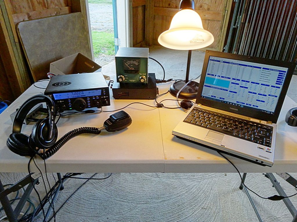
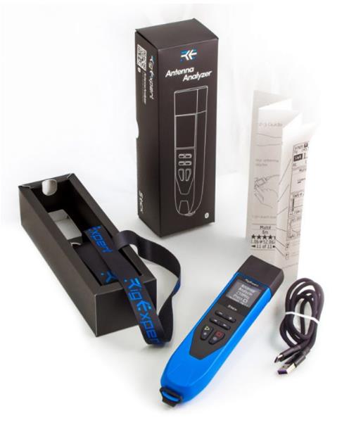
Greg Lane, N4KGL, did a test comparing two identical verticals, one on the beach near the water and another inland, away from the beach. In addition, a low dipole was added to the mix to see if horizontal polarization made any significant difference. Only simultaneous spots were used for comparison.

Using a pair of identical WSPRlite transmitters on 20 meters, Lane first established a baseline with a WSPRlite attached to each vertical. Both were set up several hundred feet inland at the same distance from the ocean. Evaluating the 55 spots, all were similar in output and operation. Using a low-power wattmeter onsite showed no discernable difference in output.

Two trials were conducted with the saltwater vs. land antenna comparison. The first one had the antenna placed at the shore and the other 700 feet inland. The second trial had them placed 200 feet apart. Results showed the saltwater vertical always beat the inland vertical for any WSPR spot with an average 10.8 dB advantage. As expected, the closer the antenna to the water, the better the gain.

In the low dipole vs. saltwater vertical scenario, the saltwater vertical was better 32 times out of 33 spots, with nearly a 10 dB advantage. The only downside was higher radiation angles.

Overall, his observations appear to support the presence of a significant saltwater gain.

Radial Placement for Maximum Gain

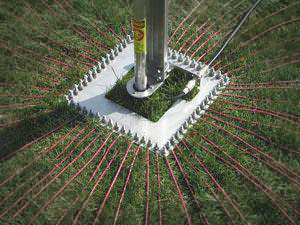
The object of the saltwater effect is to improve the ground system for better efficiency. Rudy Severns, N6LF, reminds us when AC current (RF) flows in a conductor, the current tends to flow only near the surface. The ground current for a saltwater vertical antenna is restricted to a thin layer near the water surface (skin depth). This means radials need to be near the surface to take full advantage of the saltwater effect.  

Running a copper wire with a fishing weight (or several) to the edge of the surf would probably be sufficient for casual use at the beach. A floating radial on an anchored pool noodle would be a good solution in calm inlets and tidal pools.

Tides are a challenge. Local tides can range from a foot to more than 50 feet. That would significantly cover the radials and vertical element, changing the effective length of the antenna system. A workable long-term solution could be a floating dock or a float substantial enough to support the antenna. You don’t need a long radial—attaching a piece of sheet metal or screen several feet long to the bottom or side of the dock can provide a low-resistance ground without a trailing wire.

Several DXpeditions have used pairs of 1/4 wavelength elevated radials connected to vertical antennas directly over flooded reefs. The radials need to be kept well above the water surface, even at high tides, for best results.
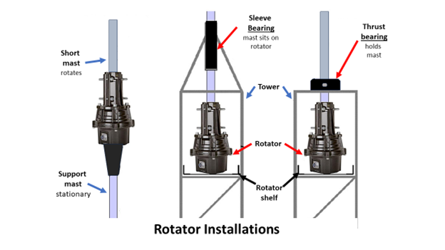
Close Also Counts

The objective with a vertical monopole antenna is not just to have any ground connection, but to have a low-loss ground plane under the base of the antenna. Think of the ocean like a huge copper sheet, just not quite as conductive. Being within a few wavelengths of an ocean is the next best thing to having radials near or in the water. Walt, K4OGO, has some videos online that discuss antenna designs and setup for use on the beach.

Going mobile? When you park close to the sea, the radio waves go over the surface, reflect and bounce off into the atmosphere and skip, just like stones or pebbles across a pond.

Reflections on Saltwater Propagation

Seawater is too good of a conductor to pass radio waves—instead, it reflects them like a mirror off of its surface. Saltwater contains Na+ and Cl- ions. Saltwater is electrically conductive because these ions are free to move in solution.

You might argue that 10 dB is only a little more than 1.5 S-units, but it can mean the difference between “can’t hear a thing” and full copy.

This might be a good time to book that beach vacation to fish for some DX!

Ocean Beach Scene with Seaweed
(Image/DX Engineering)

The post The Saltwater Amplifier Effect (& How it Impacts Your Amateur Radio Station Performance) appeared first on OnAllBands.

Ham Radio 101: Everything You Wanted to Know About Coax But Were Afraid to Ask

Coax cable has its roots dating back to the mid-1800s, when engineers developed transatlantic cable communication. These early telegraph cables were made up of a center conductor encased in a cylindrically shaped rubber-like insulator. They had no outer shield—the seawater surrounding them completed the circuit.

The coax cable we now use was based on a design developed by Lloyd Espenschied and Herman Affel at Bell Telephone Laboratories in 1916. In the 1930s, coaxial cable was used to connect radio networks, television networks, and long-distance telephone networks.

When World War II came along, military contractors cranked out coax for the war effort. The development of polyethylene made it possible to produce cheap, flexible coaxial cables for easy and quick deployment. After 1945, military surplus coax cable could be obtained cheaply, making it popular among hams in the postwar years. It became an easy-to-use alternative to open wire feed lines.

You’ve Got Coax Questions? We Have Answers

Let us help you unravel the mysteries and myths behind the cable that helps connect you to the rest of the world.

***

What Are RG, M17, and LMR Numbers?

RG stands for Radio Guide, which was the original military specification for coax cable. The number that follows the RG was just a page in the radio guide book. In reality, these are just general descriptions of the cables available.

M17 refers to the military specifications set by the U.S. Department of Defense. Mil-DTL-17, or M17, is their current standard for coaxial cable. This mil-spec has replaced the old RG numbers and ensures that the new M17 coaxial cables will stand up to tough military requirements.

LMR stands for Land Mobile Radio, which indicates its original intended use for mobile radio systems. The 400 in LMR 400 refers to the cable’s nominal diameter, which is 0.405 inches.

Every manufacturer has their own variations, including differences in shielding material, insulation, outer jackets, and other traits. Transmission loss, power handling, and other specs will vary somewhat from one brand to another. So an RG-8 cable from one manufacturer may be slightly different from that of another.

For example, the Belden 8214 version of RG-8/U has an 11 AWG stranded center with bare copper braid and an outside diameter of .403 inches. DX Engineering RG-8/U has an 11 AWG stranded center, bare copper braid, and an outer diameter of .405 inches. Loss figures and power ratings are similar, within a few tenths of a dB.

***

What Does “Velocity Factor” Mean?

The velocity factor is the speed at which an RF signal travels through a material compared to the speed this same signal travels through a vacuum. It’s expressed as a percentage. Cables with a lower velocity factor are more lossy, but that’s because they use solid insulation instead of a low-density foam or air with small spacers to keep the center conductor roughly centered inside the outer conductor. Velocity factor is also used in calculating a particular cable’s wavelengths for matching or phasing antennas.

***

Can You Bury Coaxial Cable Without Using a Conduit?

Some coax cable is meant to be buried directly in the ground and other cables are not. If you look at the cable and find the words “direct bury” on the cable then you can bury it without a conduit. Cables that are not designed to be buried will deteriorate with exposure to soil and moisture.

***

Why is Coax 50 ohms?

The best coaxial cable impedances were experimentally determined at Bell Laboratories in 1929 to be 77 Ω for low-attenuation, 60 Ω for high voltage, and 30 Ω for high power.

The arithmetic mean between 30 Ω and 77 Ω is 53.5 Ω; the geometric mean is 48 Ω. The selection of 50 Ω is a compromise between power-handling capability and attenuation. Also, 50 Ω works out well because it’s close to the feed point impedance of a 72 Ω half-wave dipole, mounted approximately a half-wave above normal ground.

***

Can I Coil Up Extra Coax?

For HF frequencies, it’s not a problem if you need to coil up small amounts of excess cable. Wrap loosely to avoid cable damage. For VHF/UHF, higher losses come into play—longer cable, more loss. The best option is to cut the coax to fit or at least buy the shortest cable you can that still fits.

***

Why Do I Get Better SWR by Adding Coax Cable?

The shield of the coax line can actually become part of the antenna. If you’re feeding a dipole that doesn’t have a balun or choke, then adding a short piece of cable will add to the antenna length, affecting the SWR reading.

Another reason is the coax can act as an impedance transformer. The impedance changes along the transmission line with standing waves. By adding some cable, you’ve changed the impedance to something your tuner can more easily match.

***

I’ve Got Leftover 75 Ω TV Coax Cable. Can I Use It with My Ham Antennas?

Sure, you can use 75 Ω coax instead of 50 Ω. If you’re feeding a dipole, 75 Ω coax is a better match since dipole impedance is about 72 Ω. In other cases, like feeding a typical 1/4 wave vertical (36 Ω depending on radials), it would be a worse match.

***

Can You Mix Different Types of 50 Ω Coax Cable to Extend a Feed Line?

For example, you have 25 feet of RG-8/U and need to extend it 50 feet to your antenna. You have 50 feet of LMR-400 available. No problem.

The only downside would be losses caused by linking the cables and differences in the cable. If you used RG-8X instead of the LMR-400, you’d likely experience a small loss of signal to the antenna.

***

With CB Radio, I Was Told to Feed My Antenna with Multiples of a Half-Wavelength—18 feet for CB. Does This Also Apply to Ham Radio?

The 18 feet length is a myth. It might be about half wavelength in free space at CB frequencies but that does not take the velocity factor of the coax into consideration. If an antenna has a perfect match at the feed point, a half wavelength in coax will repeat that match but with velocity factors running between about .66 and .85 for most modern coax, a half wavelength in coax would be between 11.88 and 15.3 feet, not 18 feet.

The proper length of coaxial cable is just long enough to connect the radio and antenna together. There’s no special length needed, no magic measurement so your radio will work better.

***

The post Ham Radio 101: Everything You Wanted to Know About Coax But Were Afraid to Ask appeared first on OnAllBands.

Ham Radio Tech: RF Ground—The Un-Ground

When it comes to ham radio, there are grounds…and then there are grounds.

Here are three types we typically find with radio systems:

  1. Safety ground
  2. Lightning ground
  3. RF ground

Safety grounds protect you from a shock hazard. The ground wire in your AC wall outlet is connected to a grounding rod driven into the earth by way of the entry panel. This provides a low-resistance path to dissipate any fault current safely.

Lightning/surge protection grounding works by routing voltage surges and spikes away from protected electrical devices. Devices such as lightning arresters are often installed on feed lines entering your shack and will direct surges to a ground rod.

Understanding RF Ground

RF ground is not the same thing as an electrical or lightning ground. The term is a misnomer—it really isn’t a ground at all. You know the dipole antenna is a half-wave long—two quarter-wave sections. If you have a quarter wave vertical antenna, it’s a monopole, which is actually half of a dipole. The RF ground makes up the other half of the dipole—you can provide this second half by adding radials to the antenna, or just a single elevated counterpoise wire that’s about a quarter wave long.

In a typical HF mobile setup, the vehicle is capacitively coupled to the ground, so the antenna is a cross between a lopsided vertical dipole—the whip being one side and the car body on the other—and a vertical with an elevated radial system.

Mobile Radios

Mobile installations present significantly more challenges than simply adding radials to your yard. The other half of the dipole is a random vehicle, a large chunk of metal of various sizes and configurations serving as a moving ground plane for your vertical antenna. The ground plane provides for return currents to the antenna and is an integral part of the vehicle antenna circuit.

One way to think about a ground plane is that it acts as a “mirror” for the active vertical element. As long as a mirror is big enough, you’ll hear your reflected signal from a distance. It doesn’t really matter if the mirror is circular, rectangular, or square. 

If the vehicle ground plane is lossy (which will happen to some extent), the performance of your antenna will suffer due to reduced current flow. Ground plane losses only add to existing losses from coil-loaded, physically shortened antennas typical of most mobile HF stations. It’s important to do what you can to minimize ground losses by improving the ground plane. Decreasing ground losses by just one ohm can make a significant increase in ERP (effective radiated power).

VHF/UHF mobile antennas have less ground losses if properly installed since their other half (vehicle ground plane) is sufficiently large for these frequencies

Bond, Frames Bond

Using the mirror analogy, a car is more like a collection of reflective tiles rather than a one-piece rectangular mirror hanging on the wall. Making the car work as a good signal reflector requires bonding.

Bonding is making low-impedance connections among the various conductive parts of your vehicle. The low impedance part is in the form of a conductive strap, such as a tinned braid, that is solidly attached between frame and body parts of the vehicle. Remember, the goal is to electrically join these surfaces into a single massive ground plane under the antenna and to improve the conductivity at RF frequencies. For larger gaps, one-inch-wide braid is a better solution, but keep it as short as possible. This helps it provide a low impedance connection.

For example, by using tinned braid you can electrically bond your exhaust pipe to the vehicle frame at several points along its length. Attach the braid to the pipe using ring clamps, screws with star washers, and soldered ring connectors to make a good connection to the car body or frame.

DX Engineering has a complete kit for exhaust bonding (below).

exhaust clamp and ground braid bonding strap kit dxe-egk-250_xl
An exhaust pipe directly bolted to the engine can be excited just like an antenna, radiating pulsing noise. An exhaust grounding system, like this kit from DX Engineering, can help eliminate noise from your mobile installation. (Image/DX Engineering)

Tinned braid is also suitable for bonding hood and trunk lids as well for enhanced ground plane performance. The hinges of trunks and hoods may not provide sufficient electrical connectivity for an effective ground plane. On pickup trucks, you can improve the ground plane by bonding its bed to the cab with braid beneath the truck using existing bolts and connection points. 

Important! When installing your antenna, be sure that the antenna mount provides solid continuity between the antenna ground side/coaxial shield and your newly bonded ground plane. Permanently mounted antennas using bolts and washers are usually best for electrical continuity, as long as they are mounted to a portion of the vehicle that’s part of the overall ground plane.

Using magnetic-mounted HF antennas will often result in poor grounding continuity for the antenna. At the very least, provide an additional ground braid for mag-mounts. Also, install your antenna as high as possible on the vehicle, with as much metal under the antenna as possible.

When improving a ground system, the main benefit by far is for transmitting. However, an improved ground plane with reduced losses helps to boost the received signal strength, thus improving the signal-to-noise ratio in your receiver.

Down to Earth

Moving from a rolling to a stationary RF ground plane, does efficiency increase or decrease with the number of wire radials?

Hams usually agree more radials on the ground are better, and it’s better to have more short radials than a few long ones. There has been a lot of debate about the extent of a radial system that might be needed. Based on a 1937 study, the FCC has suggested that a radial system consisting of 120 radials, each around 0.5 wavelengths long, would make an almost perfect ground system providing near 0 dB power loss at a low angle of radiation and a feed impedance of 35 ohms. It became the magic number for radial systems. However, such a radial system is impractical for most of us, especially on 80 and 160 meters.

dx engineering radial plate with radial wire installed
The patented DX Engineering Stainless Steel Radial Plate with 60 pre-drilled holes provides a neat and effective way to connect those essential radial wires and the coax to your vertical antenna. (Image/OnAllBands)

Sometimes you have to make a size compromise. The ARRL Antenna Handbook provides some figures for alternative configurations:

  • 16 radials of 0.1 λ gives a feed impedance of 52 Ω and a power loss of 3 dB
  • 36 radials of 0.15 λ gives a feed impedance of 43 Ω and a power loss of 1.5 dB
  • 60 radials of 0.2 λ gives a feed impedance of 40 Ω and a power loss of 1 dB

As we move toward 60 radials, diminishing returns kick in and the improvement gets progressively smaller. You’ll need to consider the cost of wire and the effort involved when deciding how far you’ll go.

There are other factors to consider, including local earth conductivity. The better the earth’s conductivity in a given region, the better the earth connection will be. It’s difficult to get a sufficiently good antenna RF ground plane on a rocky base. However, areas with moist soil provide a much better ground system. One of the best environments for a good ground connection is a salt marsh. This 1975 FCC Ground Conductivity map provides information about conductivity by region throughout the U.S.

There have been long-running discussions about the effectiveness of a vertical with an elevated ground system compared to one using a large number of radials on the ground surface. NEC modeling has shown that an antenna with four elevated λ/4-radials under ideal conditions would be as efficient as one with 60 or more λ/4 ground-based radials. In reality, you’ll probably need a few more than four.

The Ground That Isn’t Grounded

It acts as a reflector. It doesn’t radiate RF energy; it mirrors and reflects the energy. It also has a second purpose of providing the return path for RF current in unbalanced antennas.

No ground rod is involved, just lots of metal directly under a vertical antenna.

The post Ham Radio Tech: RF Ground—The Un-Ground appeared first on OnAllBands.

Get with the Program & Get More Out of Amateur Radio Club Meetings

We’ve been fortunate to have a hard-working program chair in charge of arranging our club presentations. Even when he’s wintering in Florida, he makes sure everything is ready for the next meeting and joins in via Zoom.

It’s not just about filling a time slot for the monthly meeting. Without good programs, no club can succeed or survive for very long. The program chair’s most challenging job is providing programs that will appeal to club members—not put them to sleep.

Sometimes clubs take member surveys to get ideas, seek club officer input, or ask members during casual conversations what programs they’d like to see. Unfortunately, the answer is often “I don’t know” or “Something about ham radio.” So program planners must constantly think of new ideas and strive to make every program interesting and timely.

ham radio presentation to a club
(Image/OnAllBands – Katie Rockman)

Ideas

You don’t need to reinvent the wheel. There are many potential speakers out there, including ones who have already done programs for other radio clubs. They may have a list of topics they’ll do or may even have some videos of previous presentations you can download and show to your group.

Club Members: Your group may have some individuals who have some expertise in specific ham radio topics that could be turned into an interesting presentation. Elmers are a logical choice—people who are good at explaining technical topics so they are easily understood.

Being a good storyteller also helps. One of our members did a presentation about electromagnetic pulses (EMP) and their effect on radio equipment. But he also wove in a story about our area and the Cold War.

Hamfests: Hamfests are a great place to learn more about the hobby through forums, presentations, and vendors. Many of these presentations have been recorded as PowerPoints or videos and are available online or by request.

Vendors will sometimes have presentations available or be willing to speak live to your club via video conferencing. This is a win-win situation. Your club gets a program and the vendor gets to introduce products and how they work. Our club recently had a presentation from a California-based company that sells products that suppress RFI/EMI and noise, as well as a line of baluns and antennas. We got some tips on dealing with RFI and some questions answered as well.

Ready-to-Go: Ready-made PowerPoints and videos? They’re available. See the list of links at the end of the article.

High-Profile Hams: If you’re lucky, you may be able to schedule a well-known ham to do a program. A number of years ago, our ARES group had the opportunity to hook up with H. Ward Silver, N0AX, for a video conference. John Portune, W6NBC, is one of our favorite Zoom speakers when it comes to building antennas, along with Al Christman, K3LC, who lives locally.

Contest stations K3LR and W3LPL have online video tours where you can see their well-equipped contest stations. You can also see their extensive antenna farms, complete with some bird’s-eye drone views.

Borrowed Ideas

During my travels, I’ve visited several radio clubs and seen some great presentations. An interesting one I saw in Arizona was about the pico balloon, an ultra-lightweight plastic balloon suspending a tiny, lightweight amateur radio transmitter. They’re capable of sailing around the globe—sometimes many times. Unlike other balloons, they use hydrogen because it leaks less than helium.

Be sure to get the presenter’s contact information and ask if they’d be willing to do a presentation for your club—most likely it will be done by Zoom.

Project Sessions

These don’t always have to be on a regular meeting night. Schedule them when it works best for your group—maybe a Saturday. If you choose to make it the meeting activity, keep it simple and doable within a reasonable amount of time. Things like making coax jumpers, 2-meter J-pole antennas, or a simple choke/1:1 balun can be completed during the meeting time. Individuals can be responsible for materials or the club can make a group order. (Suggestion—get the money upfront for group orders.)

A variation of this would be the show-and-tell. Members bring in projects they have completed and share with the group. They can answer questions about parts needed, how it works, and building tips.

Courtesies: Always be a class act.

Here are some things you should remember:

Before:

  • Invite the speaker at least two months in advance of the meeting.
  • Give the date, place, theme, and any other information pertinent to the meeting.
  • Specify the amount of time allotted and whether a question-and-answer session will be expected.

After Accepting:

  • When the speaker accepts, acknowledge the acceptance promptly. Provide further information about the meeting and location and agree on the presentation time.
  • Inform the speaker immediately if there is any change in the scheduled meeting time and place.
  • Send a reminder e-mail or phone call before the meeting date.

During the Meeting:

  • Start the meeting on time. The presenter’s schedule comes first—don’t make them wait for your business meeting to end.
  • Introduce the speaker with a brief bio.
  • Members who insist on chattering or being a distraction should take the conversation outside.

After the Meeting:

  • Write a thank-you to the speaker within 48 hours of the meeting. Comments complimenting the speaker on specific points in the speech are always appropriate.

When You Need to Punt

Poet Robert Burns once said, “The best laid plans of mice and men often go awry.” No one can prevent the unexpected. Everything from illness to snowstorms, floods, and technical difficulties can prevent your speaker from showing up for your program. You can plan for such emergencies by setting up a reserve of programs in case a speaker cancels—or your Zoom connection fails.

Start Here 

These links should help you find a suitable program for your meeting. This is not an exhaustive list, but it should give you some ideas.

***

DX Engineering

Various Ham Radio Topics

Educational Topics

ARRL Sections–Speaker’s Bureau 

DARA Hamvention Videos (YouTube)

The post Get with the Program & Get More Out of Amateur Radio Club Meetings appeared first on OnAllBands.

Doing a Good Turn: Choosing the Right Rotator for Your Amateur Radio Station

A rotator is a handy device used in ham radio communication systems to change the orientation of an antenna. Rotators have two parts, the rotator unit and the controller. The controller is normally placed near the radio equipment, while the rotator is mounted on the antenna mast below the antenna. It’s a must-have for DXers and operators who want to extend their reach and improve reception.

Is it Rotator or Rotor?

Let’s settle this before we move on. Hams tend to use both words interchangeably, but there is a subtle difference.

  • A rotator is a device, such as a motor, that makes something rotate—like a mast with a Yagi attached.
  • A rotor is a part of a device that rotates, such as a brake rotor or armature.

How Does an Antenna Rotator Work?

The rotator is typically mounted on the antenna mast or inside the tower, directly below the antenna, while the controller is usually placed in the ham shack near the operator’s position. The controller sends signals to the rotator unit, instructing it to rotate to a chosen heading.

Modern rotators are generally small. Due to gear reduction, the motor mechanism can be relatively compact and not draw much current. Large rotators have bigger motors, but the increase in strength is mostly due to improved gear and brake systems. The power required to turn even those big, stacked arrays is not that much.

To keep rotators from twisting in the wind, they include a braking mechanism. Smaller ones use a friction disc arrangement—when the rotator turns, the discs move apart to let the mast turn freely. When power is removed, the discs clamp together again. With medium-sized rotators, brakes consist of a heavy-duty solenoid with a spring-loaded wedge or bar that fits into indentations inside the rotating housing. On big rotators, worm gears are used and braking is done by the resistance to the gears turning backward under load.

Rotators are designed to turn a full 360 degrees, and often a bit more. That is known as overlap. At the ends of rotation, mechanical limit switches open to remove power from the motor. It’s important to leave a rotator loop in your feedline during installation to prevent stretching or breaking your feedline.

Choosing the Best Antenna Rotator

Durability is important, especially for something that’s exposed to the elements. Look for sturdy materials which can endure outdoor conditions without corroding or deteriorating over time. Opt for models with a sealed housing to protect internal components from moisture and dust for long-term reliability and performance.

Make sure the rotator you choose is compatible with your specific setup. This includes assessing antenna size, weight, and mounting considerations. There’s nothing more annoying than finding that your rotator won’t fit properly inside your tower. Also verify compatibility with any existing hardware you plan to use, such as controllers, accessories, and mountings.

It’s important not to overload a rotator. If you live in a location that’s subject to high winds, continuous winds, or large gusts, look at the wind load recommendations included with the unit. These are usually specified as a maximum antenna area in square feet or square meters. Add all of their wind load numbers together for several antennas on a single mast, and don’t forget the mast’s wind load. You can find your antenna’s specs in the manual or online.

A rotator can handle a larger wind load when mounted inside a tower section, as opposed to mast mounting, since the tower holds the mast in place straight above the rotator. Using a thrust bearing keeps most of the load off the mast, further increasing wind load capabilities. Inside tower mounting eliminates any sideways load on the rotating assembly relative to the base.

antenna rotator instructions
Mounting the rotator on a pole or mast limits the antenna’s size and the mast’s length from the rotator to antenna. This is due to the significant bending forces applied to the rotator’s clamps. Mount the antenna as close to the rotator as practical in this configuration. (Image/DX Engineering)

In the preferred tower-mounting configuration, a sleeve bearing provides additional support. Another option is using a thrust bearing at the top, which transfers the weight of the antenna and mast onto the tower and off the rotator. The rotator then just turns the antenna without the extra load.

Controlling the Rotator

Each manufacturer of rotator/controller combinations has its own design of control boxes for controlling the rotator and displaying antenna position. Yaesu’s desktop controllers provide a round dial with a 360-degree radial indication of antenna azimuth bearing. Hy-Gain HAM-IV and CD-45II models include a more traditional analog meter readout with N/S/E/W markings and azimuth readings in five degree increments.

There are also aftermarket control units that operate with many different rotators. These include the Green Heron RT-21 Series Digital Controllers and the EA4TX ARS-USB Rotator Controller with digital readout. The coolest of the group is the microHAM ARCO Advanced Rotator Controller (below) with touchscreen LCD control and azimuth information superimposed on a world map display.

moh-arco-115v_hu_xl rotator controller
(Image/DX Engineering)

If you’re old school, you may want to control your rotator manually with the clockwise/counterclockwise buttons or do point-and-shoot using the preset dial. If you plug in the call sign of a station, most logging programs will provide you with the short path and long path settings you’ll need.

Newer rotator controllers may have an interface—either RS-232 or USB. Some controllers can be connected directly to your PC to operate your unit. Older controllers may require an additional interface board that can be installed inside the rotator control box. For example, programs like PstRotator and DX-Lab can directly calculate the beam direction for long and short path and pass it on to the rotator control. Many of the popular logging software programs can also control a rotator with the help of a PC. The Ham Radio Deluxe Software suite for Windows includes the HRD Rotator Control module, which manages beam headings via any computer-interfaced rotator controller.

Interested in space? An antenna rotator with both rotational and elevation controls, like the Yaesu G-5500DC (plus related software), is essential for ham radio satellite, ISS, and EME (moonbounce) communication. It enables users to accurately track satellites and the ISS as they move across the sky. Such equipment can make adjustments quickly, maintaining a solid connection for communication.

What’s Right for You?

Decide what antenna(s) you plan to put on your mast or tower and calculate the total wind load. It doesn’t hurt to go a bit larger on your rotator. You’ll have some additional headroom and prepare for the possibility of an antenna upgrade or added antenna later on. It’s difficult to change out rotators on a tower—I know from experience.

Rotator packages usually include the necessary connectors. You’ll need to supply the wiring between the controller and the rotator, usually a six- or eight-conductor for ham rotators and three- or four-conductor for TV/light-duty rotators. They can be purchased by the foot or as ready-made cables. Other items to consider include thrust bearings and rotator shelves inside tower mounts, like the DX Engineering Accessory Shelf below for Yaesu and Hy-Gain rotators.

dxe-as25g_xl acessory shelf
(Image/DX Engineering)

Light-Duty Rotators

For smaller VHF/UHF Yagis and rotatable dipoles with wind loads >3 sq. ft. Mast/inside tower mount.

  • Hy-Gain AR-40, AR-500

Medium-Duty Rotators

For Hexbeam, tri-band 3-element monoband Yagis, and larger VHF/UHF arrays with wind loads of 8-10 sq. ft. Inside tower mount.

Medium/Heavy-Duty Rotators

For multi-element Yagis with wind loads of 15-22 sq. ft. Inside tower mount.

Heavy-Duty Rotators

For large Yagis, multiple Yagis with wind loads to 35+ sq. ft. Inside tower mount.

Editor’s note: The DX Engineering RT4500HD rotator comes in combos which include rotator and 2-inch or 3-inch mast clamp; rotator, clamp, and ARCO controller (below); and rotator, clamp, and DX Engineering controller.

dx engineering rotator and controller combo contents
(Image/DX Engineering)

The post Doing a Good Turn: Choosing the Right Rotator for Your Amateur Radio Station appeared first on OnAllBands.

Ham Radio 101: Understanding Repeater Speak

New hams often wonder what they’ll do or say over the radio after they get their license. All that jargon that hams use can seem like a foreign language to those who’ve had little exposure to amateur radio. But there is no need to be self-conscious. After reading this, you’ll become fluent in repeater speak in no time.

Common Amateur Radio Repeater Terms

Chances are your first QSO (communication) will happen on a local VHF or UHF repeater using a handheld transceiver (HT). Repeaters have their own terminology, like courtesy beep, DTMF, and split. However, this split doesn’t involve bananas and courtesy beeps shouldn’t be confused with roger beeps used by CBers. You’ve probably used DTMF before, but in a different context—on your phone.

Here are some repeater terms you may encounter while you’re on the radio.

A Glossary of Ham Radio Repeater Terms

***

  • Break: A word used to interrupt a conversation on a repeater to indicate there’s an emergency. You should say “break, break, break” to be sure you’re heard. It’s not used to join a conversation.
  • Deviation: This refers to the change in the carrier frequency of an FM transmitter produced by the modulating signal. If you’re told your transceiver is over-deviating, talk farther away from the microphone to avoid distortion.
  • Double: Two or more stations transmitting simultaneously on the same frequency, often without knowing it. The one with the strongest signal wins, but if it’s a tie, neither is heard.
  • Full Quieting: This term usually signifies a good quality signal on a repeater or FM transmission. It means that your signal is clear, free of static, and easily readable.
  • Half-Duplex: Radio communication using two frequencies, one for receive and one for transmit—one radio at a time.
  • Hang Time: This is a cure for the double. Waiting briefly between transmissions allows smooth transitions. It also gives others a chance to join in the conversation.
  • Kerchunking: You have an HT, but will it reach the local repeater? Turning it on, you briefly hit the transmit button and hear a tone in response. Satisfied, you try it again—and again. That’s kerchunking—keying up a repeater just because you can. It can really become annoying to anyone monitoring the frequency. The proper way is to say your call sign when you transmit, or something like “KE8XYZ, testing.” I even heard of one repeater that reportedly responds with “kerchunk” if it is keyed and no audio is detected.
  • Machine: This refers to the repeater system itself. You might hear something like, “The 37/97 machine has the best coverage in the county.”
  • Offset/Split: If the repeater output is 146.840 MHz, the input or the frequency the repeater receiver listens on is 146.240 MHz (600 kHz below 146.840 MHz). The offset prevents transmit and receive signals interfering with each other at the repeater.
    • If you’re tuned to 146.840 MHz, when you push the mic button your radio automatically transmits on 146.240 MHz, 600 kHz down from 146.840. When you release the mic button, your radio switches back to 146.840 MHz to listen on the repeater’s output frequency. Confused? No worries—virtually all ham radios sold today set the offset automatically.
  • Open Repeater: A repeater that may be used by any licensed ham radio operator is considered open. Closed repeaters are restricted to exclusive groups, such as members of a club.
  • PL Tone: PL (private line) tones or CTCSS (continuous tone-coded squelch system) tones are sub-audible tones of 300 Hz and below that are transmitted and detected by radios and repeaters. The tone is transmitted when you talk, and the repeater lets you through if you’re using the correct tone. It’s used to prevent people accidentally keying up on a repeater frequency or a repeater interfering with another repeater during a band opening.
  • Repeater Directory: It’s a publication that lists repeaters in the U.S., Canada, and other areas. A popular repeater directory is published annually by the ARRL (below). You can also find directories on the Internet from many sources. Do a repeater directory search to locate them.
  • Simplex: This is communication where hams receive and transmit on the same frequency without using the repeater. It’s also called talk around. You can do this to avoid tying up the repeater, especially if you’re not far apart.
  • Time Out: No, you don’t have to sit in the corner. This happens when a person talks too long and the repeater time-out timer (TOT) temporarily shuts down the transmitter. There will be a short pause, then the repeater will reset and the conversation continues.
ARRL Repeater Director book, 2024 edition
(Image/DX Engineering)

Try the DX Engineering N8DXE Repeater!

If you’re ever near Akron, Ohio, you can access the DX Engineering Amateur Radio Club (N8DXE) repeater at 146.985 MHz. It was recently upgraded to the Icom ID-RP2010V repeater, which allows for both digital and analog operation. D-STAR gateway access is unchanged. For analog, there is no PL to access the repeater. However, the repeater will transmit a 110.9 Hz tone so you can set up your analog radio for Tone Squelch. This will allow you to filter out the digital traffic. Of course, if you are in digital mode, it already filters out the analog traffic.

The post Ham Radio 101: Understanding Repeater Speak appeared first on OnAllBands.

Getting Started with BOTA, Beaches on the Air

If you thought Parks on the Air (POTA) was the only portable operation event in town, meet BOTA.

Beaches on the Air promotes ham radio portable operation from beaches. BOTA has awards for activators (those who operate at the beaches) and chasers (those who contact them). Radio amateurs can participate from any beach, country, or region around the world. The program brings together thousands of hams from six continents, and new ones are joining every day.

beaches on the air BOTO logo
(Image/Beaches on the Air – BOTA)

BOTA now lists more than 30,000 beaches and they’re constantly adding new beaches as they become active. You may activate the same beach as many times as you like, gaining additional points each time. There are no restrictions on how you travel to the activation location or the power source you use for your station. BOTA invites you to submit your beach activation images and videos.

Besides promoting fun amateur radio practices, the program offers other benefits as well. It encourages participants to get out of their shacks, do mild exercise, increase their vitamin D levels, and work on their tans. It’s also relaxing to sit on the beach and sip your favorite beverage. Kick back, chill, and leisurely log those contacts. Don’t forget to tell everyone what a wonderful time you’re having during your QSOs.

Beach Operation

Conditions at the beach are quite different from POTA, IOTA, SOTA, and other ‘OTA activations. Be aware of tide schedules, high winds, and changes in weather. Locate yourself where you won’t have to constantly move away from an incoming high tide.

You’ll likely be inclined to bring more things: beach chairs, umbrellas, coolers, and other items. After all, it’s also a trip to the beach. Be realistic about what you can comfortably carry—sometimes it’s a long walk.

Five-gallon utility buckets are great for carrying coax, antenna parts, tools, and other supplies. After you’ve emptied it, the bucket can be flipped over and used as a stand for the radio. A pack seat will also fit in the bucket and give you a place to sit or set up additional equipment. Tote bags or backpacks will help keep your radios protected.

Securing your antenna properly is important. Most operators prefer a lightweight telescoping pole at the beach, like those from DX Commander or SOTAbeams, to hold a 1/4 wave of wire. These poles have a minimal wind load and those <31 feet will generally not need guys. To make them freestanding, you’ll need a sand spike—a tube for holding fishing rods or beach umbrella holder that screws into the sand. Be sure the bottom of the pole will fit inside before you invest in one.

The beach’s biggest draw for hams is the “saltwater amplifier,” nature’s reflector for your signals. Forget burying a batch of radials in the sand because you only need one. Run it toward the water at the edge of the waves or tie a fishing weight to the end and give it a toss into the waves. Add a quarter-wave wire vertical and you’re good to go. Using the saltwater ocean as counterpoise can give you up to a 10 dB gain. A 10W QRP signal becomes a 100W signal with a very simple antenna system—really awesome!

Getting Started with BOTA

Interested? First, create an account at BeachesontheAir.com. While you’re waiting for your registration to be processed, search for activators listed on the website. Listen to a few QSOs, then call when they’re on the air. The activating station will provide you with a code during the exchange.

After you receive the code over the air from the activator, sign into the BOTA site. Under the user menu, select “Add chaser report redeem code.” Enter the code. If you have just made the QSO, click yes and add the frequency and mode so a spot is placed on the BOTA home page.

You can also keep a log and enter it all later. You have one month to enter the code. If for some reason you have forgotten the code, you can enter the activator’s call sign and then choose the activation site. Activators and chasers are not required to submit logs.

When you’re ready, plan to become an activator. You’ll go to the BOTA website and choose “Announce activation, Generate code.” Search for your beach and complete the information required. Once saved, the Admin will review the beach. If there are no issues, it will be added to the system.

There’s also a Beaches on the Air Facebook group where you can find additional information.

BOTA Operation Procedures

Here’s a basic summary of the definitions, rules, and procedures:

Beach Activation Boundary: Defined as the area between the water and the road that runs parallel to the beach. This usually includes beach car parks and may include grassed areas, paths, etc. Keep in mind the program is “Beaches on the Air,” not “Across the road from a beach on the air.”

  • Setup Location: Activators can set up a portable station or activate from a vehicle. Activators should abide by local laws regarding the setup of a portable station and obey any directives given by local authorities regarding station setup. Activators need to be aware of other beach users around them and always make sure that their setup is safe for themselves and others.
  • Operating Frequencies and Modes: Any amateur radio frequency can be used and all modes are permitted where the activation code can be clearly transmitted. Repeater contacts don’t count.
  • Multi-Person Activations: When two or more stations are activating from the same beach at the same time, all activators need to individually set up their information on the system and use their individual activation code over the air with their chasers. Each activator should take their own photo of the activation site and later upload it. There is no club/team scoring.
  • Repeat Activations: It is possible to activate two or more different beaches on the same day using different codes, but you must physically move your entire setup from one activation to the other. There’s a minimum one-hour break between the end of an activation and the start of a different one on a different beach.

The post Getting Started with BOTA, Beaches on the Air appeared first on OnAllBands.

Ham Radio 101: Do I Really Need an Amplifier?

Everyone wants to improve their signal quality, work more DX stations, make more QSOs, and earn higher contest scores.

Should you buy an amplifier or beef up your antenna system?

Both are good ideas, but is amping up worth the additional investment?

What’s in Your Ham Station?

For starters, let’s assume that you have a typical shack. Your 100W transceiver connects to a coax-fed dipole (or several) through a built-in or external antenna tuner. Thanks to the tuner, your rig can put out full power regardless of actual antenna/feedline SWR on the various bands you work. You use the same basic setup as most of your ham friends and the guys in the local radio clubs. 

If everyone has been using this setup, it must be good, right?  Maybe, maybe not. You tune in some stations calling CQ, but for some reason they don’t always answer your reply. Maybe it’s band conditions, or a stronger station is overpowering your signal. Shouldn’t it be easier than this?

You pause for a moment and dream about adding an Acom 1000 HF+6 Meter Linear Amplifier to your station (see below). Certainly, 1kW will help you kick butt in a DX pileup and let you cut though all the noise and interference. Flip the switch, tune, and be heard!

Then reality sets in and you go back to making calls with your 100W radio.

ACOM 1000 HF + 6 Meter Linear Amplifier aom-1000_it_xl
(Image/DX Engineering)

Although you may not know it, you can likely get more signal for a lot less money. Rather than shelling out thousands for an amp up front, I’d suggest you try a three-step approach to getting your signal heard. Utilizing all three will get you the best results in the long run, but you may find improving your antenna system is enough.

***

A 3-Step Approach for Improving Your Ham Radio Signal

***

Step 1: Skill vs. Brute Force

Anyone can fire up a monster amplifier and generate a loud signal—and many do. It doesn’t take a whole lot of skill to muscle your way through a pileup with a legal-limit amp and snag that rare station.

But you can also practice your operating skills, which won’t cost you a thing.

Skill has tangled with brute force for a long time. Take the Marvel Universe, for instance. The Hulk relies on brute force, fueled by anger. His strength continues to increase until he’s strong enough to take out his enemy. In contrast, Captain America has skills like marksmanship and martial arts, and is an expert tactician and field commander.

Point is, although Captain America is an enhanced soldier, those skills are really his superpower—so develop your operator superpowers and make yourself heard!

One strategy I learned is to transmit on a frequency slightly above the main pileup or the last station worked. The DX station will often explore the upper edge of a pileup if he can’t pick out calls from the main section of the pile.

Another is to delay for a second or so sending your call so the last letter or two extend past the main buzz of the pileup. In my case, the station would then hear the “SH” and send “SH?” Then I send my call again and make the QSO. Timing is everything.

Also, CW and digital modes will give you significantly more mileage than SSB. Generally, they work well at power levels of 100W or less, but you should use 30W or less for digital to keep from damaging your finals.

Step 2: Budget-Friendly Renovations

Consider updating your antenna system as the next step to improving your signal. One way to improve your signal is to move antennas higher in the air. Build a taller mast, find a taller tree, or put up a tower.

If that dipole just isn’t cutting it, try a new secret weapon—a full-wave horizontal loop set as high as possible. Feed it with coax and use a tuner on bands above the fundamental frequency. That’s a quick and relatively easy way to snag an extra 2 to 10 dB, depending on frequency. 

Changing the feedline can mean more dBs. Disconnect the coax feedline from your dipole and replace it with 450-ohm ladder line. By using low-loss 450-ohm line you’ll likely experience a 6 to 20 dB increase.

If coax feed is your only option, upgrade to a lower-loss coax. For example, you’ll gain 0.7 dB by switching from RG-8X to 400Max and 1.3 dB by replacing RG-58 with RG-8X–based on 100 feet @30MHz. Minimize the number of connectors, switches, and adapters in your feedline system to prevent additional loss.

For less than the price of an entry-level amplifier, you can buy a Cushcraft A3S tri-band beam antenna and a medium-duty rotator. This pair, mounted reasonably high above ground, will offer a 5 to 7 dB steerable improvement to your signal. By rotating a directional antenna, you can often achieve a twofer—boosting the signal you’re trying to receive while attenuating unwanted signals.

On SSB, activate your rig’s speech processor with the proper settings. There’s another 3 dB (or more) improvement, this time in the modulation department—no purchase necessary.

Step 3: Power Trip

If you can hear people but they can’t hear you, it may be time to consider an amplifier. Most amateur radio operators find that when they use a reasonable antenna system, 500 to 800W of amplifier output is usually enough power. These midrange amplifiers also use readily available 120 VAC, so there’s no need to add a 240VAC line to your shack.

An amplifier that produces 750 to 800W of output power will have a 9 dB gain advantage over the 100W signal, which is about 1 1/2 S units. If you go from 750 to 1,500W, you will have a 3 dB advantage, which is only one half of an S unit. So why go to 1,500W? If you are in a DX pileup, that 3 dB may be enough for you to be heard over the other stations. 

If you operate on the lower bands—160 or 80m—there’s an added reason to get yourself an amp. Manmade and atmospheric noise can make communicating a challenge. The primary problem is thunderstorm activity. It creates radio noise that is reflected off the ionosphere just like regular radio signals. I’ve participated in nets on both 160 and 80m and recommend using an amp capable of 1 kW or more for reliable communications.

Wait…There’s More

Buying a new amp has a domino effect. You’ll need a beefier antenna tuner and wattmeter to handle the increased power, not to mention upgrading your antenna system to accommodate the extra power. A 240VAC line is mandatory for larger amps running at full power. Materials and an electrician to install them will likely run several hundred dollars more.

Keep in mind that once you have the power, you’ll want more—not less. You’ll also note that even a basic 500 to 800W amplifier will set you back $1,500 or more. Buy the best you can afford and use it responsibly. 

Here are some amplifier candidates to consider at DXEngineering.com, including the FlexRadio Power Genius XL below.

flexradio power genius xl hf rf radio amplifier
(Image/DX Engineering)

To Buy or Not to Buy a Ham Radio Amplifier

After looking at the facts, how much improvement does your station need? As always, the choice is yours. Amplifiers are the final option, especially after you’ve honed your skills and tweaked your antenna farm. Add a 10 dB amplifier to a 7 dB beam antenna and you’ve got a 17 dB improvement in signal strength.

When conditions are poor, an amp can make the difference between being heard and being lost in the noise.

The post Ham Radio 101: Do I Really Need an Amplifier? appeared first on OnAllBands.

Ham Radio Product Review—FlexRadio Tuner Genius XL

What’s your idea of the perfect tuner? Here’s my wish list:

  • Easy to operate
  • Finds and remembers settings
  • Covers 160-6 meters
  • Matches just about anything you can throw at it
  • Automatic operation

There are some good candidates out there, like the FlexRadio Tuner Genius XL. It will convince your radio that it’s connected to a 50-ohm antenna system—or close to it.

This review is based on the Tuner Genius XL (TGXL) 1×3 model, but there’s also an SO2R version.

FlexRadio Tuner Genius XL , front
(Image/DX Engineering)

Both are identical except for the antenna interface. Two transceivers and two antennas can be connected simultaneously on the SO2R model. The 1×3 version accommodates one transceiver and up to three connected antennas. During operation, one of three antennas is selected.

On both models, switching is done via remote control by LAN, serial interface, or individual signals from the transceiver.

FlexRadio Tuner Genius XL, rear fri-tgxlso2r_kc_xl
Tuner Genius XL SO2R model, back (Image/DX Engineering)
FlexRadio Tuner Genius XL SOR Version, back fri-tgxl_ld_xl
Tuner Genius XL 1X3 model, back (Image/DX Engineering)

FlexRadio Tuner Genius XL Features

The Tuner Genius XL is the first self-contained SO2R (single operator, two radio) tuner in the amateur market. This tuner covers 1.8 MHz to 54 MHz with the ability to tune up to 10:1 SWR. All functions can be controlled either from the front panel of the tuner or by using a Windows computer software application. This allows the Tuner Genius XL to be moved off the desktop to a more convenient location, while still maintaining full control by computer.

Handling up to 2,000W ICAS of power, the Tuner Genius XL has considerable headroom above the 1,500W legal limit. Accurate peak responding RF power and SWR meter displays are also provided, so you really don’t need a separate watt/SWR meter in your shack. The easy-to-read 4.5-inch color display is centered on the front panel.

Electrically, the TGXL is a pi network tuner with three changeable elements, a series inductor with two capacitors to ground—one at the input and the other at the output. A pi network is a good choice for matching the relatively low 50-ohm impedance of a transmitter and relatively high and unknown impedances of an antenna system. The combination of discrete L or C components determines each network element’s value—one of 255 possible values. This provides 2553 (16,581,375) possible matching combinations. Because the matching circuit also forms a low pass filter, it also provides additional harmonic suppression.

All of this is enclosed in a sturdy metal case, resembling the FlexRadio Power Genius XL companion amplifier. The Tuner Genius XL provides three operational modes: standby, operate, and bypass selected by two front panel buttons.

Plays Well with Others

The Tuner Genius XL easily integrates with the Power Genius XL RF amplifier and all FLEX-6000 series HF transceivers. These station components communicate with each other using a LAN connection via ethernet or Wi-Fi. When used in conjunction with a Power Genius XL amp and a FLEX-6600 or FLEX-6700 transceiver, you can have a fully functional SO2R station.

You may enjoy this review on the FlexRadio Power Genius XL Amplifier too.

In addition, the TGXL supports frequency detection from other brands of HF radios at the inputs and automatically chooses the appropriate setting for tuning. This band-switching mode may require double-keying before the first transmission for non-Flex radios before it tunes. You still need to set up a PTT or the TGXL will not go into TX mode. RF Sense is for frequency detection. Alternatively, you can use data from your radio.

TGXL PTT lines are opto-isolated, but they won’t tolerate high voltages or an AC voltage. Be aware of this if you use an older transceiver. Incoming PTT line specs should be checked before you connect. Some operators may want to use a keying buffer in all cases as insurance to prevent any possible damage to the exciter or tuner due to possible transient voltage spikes or RF ingress.

Setup: TGXL User Interface

For Flex radios, you start the Tuner Genius XL Windows Utility program on a Windows-based computer. It will find your Tuner Genius XL tuner automatically and direct you to the copy of the front panel display.

The configuration has five separate tabs: network settings, CAT/CI-V information, FlexRadio settings, Antenna Genius (a remote switchbox option), and other, which is a collection of miscellaneous settings. These allow you to customize radio, antenna, and other settings for your particular station.

The user interface has all the same functions available on the front panel. All you need to do is point and click.

Tuning Process for the FlexRadio Tuner Genius XL

There are two modes of tuner operation: manual and automatic. In automatic mode (default), you start a tune operation to better match the transmitter and the antenna system. If one is found, the match solution (L/C/L values and frequency) is stored in memory and automatically used when the frequency of the transmit slice is within the match frequency range, with the same antenna selected.

Go through each antenna on each band once, then the tuner will use the tuning values closest to your operating frequency for the antenna you’re currently using. There are 10 memories per band, and up to four tunings per band can be saved. Once set up, TGXL will remember individual settings for each frequency change.

Band configuration settings let you select ranges of frequencies that the tuner will selectively ignore for resonant antennas. For example, suppose your 80M dipole is resonant at 3750 kHz. In that case, frequencies near this value can be bypassed by selecting the Enable Bypass check box in the 80M row, then entering the range of the bypass in the Bypass Start and Bypass Stop columns.

Manual tuning is also possible to tweak a current or saved setting. Three front panel controls allow manual tuning by turning one of three knobs found along the bottom edge of the front panel or clicking on them in the TGXL control app on your computer. The first and third knobs select the capacitance with the second adjusting inductance values.

Once you have tuned a frequency, the solution is saved. When you change bands on the radio, the tuner senses your new frequency and is ready almost instantly. It uses relays rather than servo-controlled inductors and capacitors.

TGXL on the Air

I have several HF antennas at my location, so I chose an inverted L (160/80m) and a rotatable 40m D-40 dipole. These would require tuning somewhere within the range of their coverage. In addition, I used a triband Yagi on 20/15m to test the abilities of a non-Flex radio (Icom IC-7610).

The FLEX-6400M and an Icom 7610 were both connected through a Power Genius XL to the tuner. The Flex used the LAN for PTT and frequency tracking. The 7610 used a CI-V and conventional PTT line consisting of a shielded cable with RCA connectors on the A inputs. Internal tuners on both radios were bypassed.

Starting with the potentially challenging 160M band on the Flex, I checked for matches on five frequencies across the band. All read 1.26:1 or less using the onboard TGXL SWR meter. The seek time for 160 meters was under 10 seconds. For 80 and 40 meters it took less than five seconds to arrive at an initial tuning solution. Once stored, the memory settings are applied within milliseconds. When returning to a previously memorized band segment, the TGXL makes one relay click noise and it’s tuned in a fraction of a second.

With the IC-7610, the frequency tracking followed the radio. The front panel tune button was used to set up the memory locations, requiring a carrier from the 7610. I also found that the TGXL control software would duplicate the tune button function on the front panel for the Icom. Tuning setup can be done from any radio that produces band data for the TGXL.

Finally, I changed the 80m settings to add a bypass start/stop. Since the measured antenna resonance was 3780 kHz, I set the bypass to 3730 kHz through 3830 kHz (50 kHz each side of resonance.) The tuner ignored the range set to be bypassed and continued to access memory settings for the other portions of the band.

Overall Impressions of the FlexRadio Tuner Genius XL

Whether you’re currently a Flex owner or not, this is a tuner you should consider. It works well in the SmartSDR ecosystem and is built like a tank. At the time of writing this review, I know of no tuner that accommodates two radios simultaneously.

It’s a perfect match for the PGXL amp, which also has SO2R capabilities. It’s also compatible with the Antenna Genius 8×2, a smart matrix antenna switch that supports eight antennas and two radios while operating on your existing LAN/WAN.

If you have a PGXL or other solid-state amp, the TGXL is a must, since the tuning is precise and repeatable. You’ll also be protecting those expensive transistor finals. Once you have set up the TGXL with tuning solutions for your antennas, you are good to go. Because the TGXL quickly follows the radio’s frequency as I tune my 6400M and IC-7610, a tuning solution is ready to go even before I transmit.

The post Ham Radio Product Review—FlexRadio Tuner Genius XL appeared first on OnAllBands.

Ham Radio Product Review: Power Genius XL Amplifier—Go on a Power Trip

Solid-state amplifiers have become mainstream as vacuum tubes have become more difficult to find and solid-state power capabilities have increased.

Now it is commercially feasible for amateur radio amplifier manufacturers to provide maximum legal output power, plus headroom, using the new generation of solid-state devices. Though comparable tube amplifiers are currently less expensive, it’s likely that the price point on solid-state amps will continue to drop.

If you are searching for a high-performing solid-state linear amplifier, the Power Genius XL (PGXL) amplifier is exactly what you need. It’s the only amplifier on the market that allows fully integrated single-operator, two-radio (SO2R) operation using a single amplifier. It also works equally well in single-operator mode.

The Power Genius XL transforms your FlexRadio FLEX-6000 series radio (or any other brand radio) into a legal-limit powerhouse with headroom to spare.

flexradio power genius xl hf rf radio amplifier
(Image/DX Engineering)

The PGXL delivers 1,500 watts thanks to the pair of NXP MRF1K50H LDMOS transistors, each rated at 1.5 kW dissipation. That’s 1,500 watts at full ICAS duty cycle using any amateur mode. Also unique to the PGXL is a technology called MEffA™ (Maximum Efficiency Algorithm). It controls the DC voltage and bias levels on the PA to yield high efficiency and low intermodulation distortion.

This amplifier is built to broadcast industry standards, incorporating low pass and high pass band switched RF output filter networks. All signal harmonic energy is directed into an internal resistor load, eliminating the reflection of this harmonic energy back into the amplifier.

This feature improves amplifier stability, distortion, and efficiency.

PGXL Amplifier Features

Up front is a color touch screen with power and SWR readings shown as horizontal bar graphs.  Temperature and voltage readings are displayed numerically. The A and B input/outputs show amplifier class settings, band information, and keying method. Rounding out the display is the local IP address and software version.

You can also communicate with the amplifier using Power Genius XL Utility software (downloadable from the FlexRadio website), which mirrors the display settings on your computer screen.

flexradio power genius xl apmplifier screen display
(Image/DX Engineering)

To the left of the display is a horizontal bar. I originally thought this was just part of the front panel design.

Actually, it’s a handle built into the PGXL that makes carrying the amp easy, compared to holding it like a box. Behind the handle, you’ll find an open space for airflow, populated with LED lighting indicating the operating state. Yellow is standby, green is operate mode, red is transmit, and purple is firmware update.

Band switching is automatic, controlled via a transceiver interface, LAN for Flex radios or by sensing the RF input signal. The PGXL operates at full power with an antenna system SWR up to about 2:1. Output power folds back between 2:1 and 3:1. Above 3:1, the amplifier stops transmitting.

The unit does not include an antenna tuner, but a companion Tuner Genius XL is available at DXEngineering.com.

The Power Genius XL features a predistortion sampler output for transceivers that can use this signal for predistortion processing to reduce transmitted intermodulation distortion. There are separate predistortion samplers for the A/B transceiver inputs.

Separate bias settings can be used for linear modes and nonlinear modes to increase efficiency when possible. Class AAB (more linear, less efficient) is intended for AM, SSB, and PSK modes. Class AB (less linear, more efficient) is intended for FM, CW, RTTY, and other digital modes. Bias selection is automatic when the amplifier is paired with a FLEX-6000 series transceiver. It can also be selected manually from the front panel or by using the PGXL Utility software.

Easy Peasy

Adding a PGXL to a FlexRadio FLEX-6000 series transceiver is a simple five-step process:

  • Plug the PGXL into 240 VAC power
  • Insert an ethernet LAN cable
  • Connect the coax from the radio(s)
  • Connect ANT 1 and ANT 2 to the respective inputs of the amplifier and connect the antennas to the two outputs of the PGXL
  • Install the desktop software on your PC and configure the PGXL to your radio
rear view of power genius xl radio amplifier
(Image/DX Engineering)

Only have 120 VAC outlets? The internal power supply will automatically sense the input voltage. Maximum power output is limited to 700W, and the power meter scales adjust to reflect this. Drive power is also attenuated to minimize the possibility of overdriving the amplifier

The Flex PGXL can also be easily configured to work with any radio from other manufacturers because it supports CAT, CI-V, BCD band decode, and RF sensing. Detailed information appears in the operating manual.

How Does it Perform in Everyday Operation?

The PGXL is a device you can forget about during operation. It can be left powered on in standby for minimal current draw and jumps to instant operation when you press operate. The standby/operate functions are fully integrated into SmartSDR Maestro and SmartSDR iOS. In fact, an entirely new set of meters can be selected in the amplifier app to monitor the PGXL power output, SWR, and temperature on your computer screen.

You can place the amp just about anywhere that your home network and sufficient AC voltage is available. For example, I’ve placed mine in another part of the shack, since my operation position is a bit crowded. If you use any of the FLEX-6000 series radios, Tuner Genius, or Antenna Genius, you’ll find that they communicate with each other on the network.

First Impressions of the Power Genius XL

Power Genius is a reasonably compact unit, especially for one that delivers 1,500W on 160 through 6 meters with about 50W of drive. The amplifier power switch is on the rear panel. I found this unusual, as most amps have them on the front panel. It’s not a deal breaker, but sometimes inconvenient.

I’ve had the Power Genius XL with the FLEX-6400M transceiver and the Tuner Genius automatic antenna tuner for a while. Setup is relatively simple—just configure the PGXL touch screen or computer app for the radio(s) you plan to use.

The FLEX-6600/6600M provides SO2R operation from one box, or you can choose any two transceivers. In my case, I don’t have an SO2R configuration. I use the A input/output for my Flex radio and the B input/output channel for my other radios—the best of both worlds. There’s 70dB of isolation between the A/B connections and only one can transmit at a time. It’s almost like having two amps.

On the Air

I’ve used the Power Genius XL on all bands from 160 through 6 meters, primarily on SSB. My antennas include a Yagi for 20 through 6 meters, inverted-L wire for 160 and 80 meters, rotatable dipole for 40 meters, and a Big IR vertical for 80-6 meters.

When the going got tough during poor band conditions or atmospheric noise on 160/80 meters, the PGXL made the difference between QSO and no QSO. I generally leave it in standby mode so it’s ready to go at a moment’s notice. 

When using the FLEX-6400M, the amplifier tracked the band using the ethernet connection to communicate. Using other rigs like the Icom IC-7610, the amplifier sensed the frequency and selected the proper band if I used the C-IV connection—in this case a standard 3.5mm male to male audio cable. The TGXL tuner adds additional versatility, something to be discussed in a future review.

Virtually any transceiver that provides a PTT output to control an amplifier will also work with the PGXL. The PTT control is optically isolated with very low voltage and current, so it will work with any transceiver. This requires a brief pulse of RF from the transceiver, then release of the PTT, VOX, or CW keyer. The amplifier then operates normally following a band change.

The PGXL keeps its cool with fans in the power supply unit, the RF deck, and the filter compartment. The firmware manages the fans independently based on information from sensors in each compartment. To help manage that, the PGXL offers three user-selectable fan profiles (standard mode, contest mode, and broadcast mode) in order of increasing fan speed.

In standby mode, the PGXL fan is quiet after it cools down. In operational mode and receiving, the fan is only moderately noisy. As with other solid-state legal-limit amplifiers, the fan gets louder after a long full-power transmission as it tracks the internal temperature and provides more cooling.

Remote operation is supported by Flex SmartSDR. This is very helpful for me since I often spend the winter months in warmer climates. I can pull out an iPad or iPhone, turn on the station remotely, and get on the air. You can bring the amp online or offline from your laptop, tablet, or smartphone and monitor. It also will let you monitor PGXL power output and SWR.

Currently there is no remote on/off control built into the amplifier—perhaps that may be added in the future. In the meantime, I use a homebrew remote relay switch. As for connecting to the PGXL utility, it can be done through a VPN connection and a Node Red program running on a PC or Raspberry Pi. There’s plenty of information on this, the relay switch, and other subjects on the FlexRadio community discussion board.

PGXL Amplifier Review Summary

The FlexRadio Power Genius XL is a great solid-state, maximum-legal-limit amplifier for 160 through 6 meters. It integrates seamlessly with FLEX-6000 series radios, but it also works well with other transceivers, with or without band data connections.

As you might expect from an amplifier at this price point, it has outstanding performance. It produces 1,500W output on any band with about 50W drive and hardly breaks a sweat—something that cannot be said about just any amplifier. It will cruise along in any mode, including digital, at full throttle/full output all the time. Of course, the amp will fold back or shut down extremely fast if a fault is found, making the PGXL bulletproof.

But wait, there’s more. The FlexRadio Power Genius XL manual and other documentation is available from DX Engineering.com to give you the bigger picture.

The post Ham Radio Product Review: Power Genius XL Amplifier—Go on a Power Trip appeared first on OnAllBands.

Field Day: Things You’ll Need & Wished You’d Brought

Every Field Day setup is different, depending on location, number of people, access to trees, number of stations operating, and more. Chances are you’ve participated before and have a basic checklist of items you’ll need. It probably includes items like radios, antennas, generators, tables, chairs, shelter, food, and other necessities.

But sometimes you get that feeling that you left something behind. You’re not sure what it is, but you’ll find out soon enough, like when you discover the extension cord isn’t long enough or try to sit down and realize you left the folding chair at home.

Forehead slap, followed by “How could I forget that!”

We can’t prevent these awkward moments, but there are some items we’d suggest to make your Field Day experience more productive and comfortable.

Let There Be Light

wearable headband light
(Image/DX Engineering)

It’s nighttime and the glow from your transceiver’s dial isn’t quite enough to see your iambic keyer or the coffee cup you’re about to knock over. If you’ve got some power to spare from your generator, a gooseneck desk lamp will be a big help. If not, then a compact emergency lantern will last the entire Field Day (and then some) on a handful of batteries.

Need to do cable repair in the dark or find your way to the porta-john? A basic handheld flashlight will guide the way.

Comfort First

The operator can only tolerate what the seat will endure. The folding chair-in-a-bag is great for relaxing but awkward for serious operating. Our club president brings a large, comfy desk chair—fortunately, he has a truck to haul it to the FD site. However, a sturdy folding chair with upholstered seat and back will easily fit in most cars and provide reasonable comfort. If it’s a basic metal model, consider adding a memory foam cushion. What the heck, bring a foam cushion anyway.

Fold-in-half resin tables are compact and easy to carry. Most are also height-adjustable for a comfortable working area.

They also stand up to spilled coffee.

portable field day ham radio station on a folding table
(Image/OnAllBands)

Keep Cool

Bring a fan. Small desk fans are a start, but large and quiet are better—think box fans. If you live in a warm, dry climate, misting fans can lower ambient air temperature up to 25 degrees F.

Tool Kits

Everyone has their own vision of the perfect tool kit. Most include socket sets, screwdrivers, pliers, wrenches, hammers, battery powered drills, long tape measures, spare hardware, and clamps.

There are other tools worth considering. One that tops our list is Vise-Grips. They can be used to hold small parts together temporarily and to clamp something quickly and securely in place. They’re also a great tool for ground rod or rebar stake extraction. Lock them in place near the top and twist the rod out.

A mini sledge is a close second. A two- to three-pound version is usually ideal for most jobs and better than a standard claw hammer for driving stakes and ground rods.

Square Peg, Round Hole

Our Field Day crew has tried to standardize audio, power, and RF connectors over the last few years. For the most part, it has worked. But once in a while we have to deal with an odd connection of some kind, replace worn connectors, or extend coax runs. Keep male and female versions of the coax adapters—UHF to N, BNC, or SMA and a good supply of SO-239 barrel connectors (below) for chronic feedline shortages. For audio adapters, 1/4 to 1/8 inch, 1/8 to 1/4 inch, and the mono/stereo versions are a good start.

4 DX Engineering SO-239 Barrel Connectors
(Image/DX Engineering)

Anderson Powerpoles offer a standard for 13.8 VDC connections—one plug fits all and prevents accidental polarity reversals. Four-way splitters are handy for multiple station items like radios, tuners, and keyers.

Electronic Repair & Diagnosis

Antenna analyzers are a must for tuning antennas and checking feedline. The RigExpert STICK-230 (below) fits easily in a pocket and has a long battery life.

rigexpert antenna analyzer stick
(Image/DX Engineering)

Digital multimeters can help with continuity checks, voltage/amperage readings, and battery solar cell and power supply diagnosis. Include a comprehensive tool kit with everything you might need for quick fixes: soldering iron and solder, electrical tape, wire cutters and strippers, crimp tools, screwdrivers, coax prep tools, and spare PL-259 connectors.

Rebar, Zip Ties & Gaffer Tape

You can’t have enough stakes. But when shopping the big box stores, I found plastic, wood, and not-so-rugged metal versions. The more durable rebar pieces cut into one-, two-, or four-foot sections appear to be a sturdier choice for guy lines. Keep them driven close to the ground or mark them clearly so as not to be a hazard.

You can use two- or four-foot rebar to help keep your tent pole or light telescoping masts from sliding around while you do your guying setup. Drill a 5/8-inch hole in the center of a small scrap of plywood or 2 x 6 stud, then place it on the ground to protect the pole. Drive the rebar into the ground through the hole, leaving about a foot or so protruding. Slide the mast over the rebar. You may want to protect fiberglass poles by inserting a slightly smaller diameter piece of PVC inside the bottom of the mast.

Zip ties? They’re probably one of the handiest inventions ever made. The obvious use is for bundling cable and rolling it up neatly for next year’s Field Day. Break a zipper-pull on your backpack or a shoelace—replace it with a zip tie loop. Use multicolor zip tie kits to color code wires. Flag cable ties let you easily identify or mark items.

Leave your duct tape at home. Sure, it will work, but it leaves a sticky residue when it’s removed or relocated. Gaffer tape leaves little to no residue when removed. With gaffer tape, you can secure cords and gear, mark spots, label and mark gear, etc., and then remove the tape without mucking up your stuff.

Backup Equipment

Test it before Field Day and it will work. Use it during Field Day and it might fail. Murphy’s law will prevail: “Anything that can go wrong will go wrong, and at the worst possible time.”

Be prepared to replace an entire station or parts of it: power supply, radio, microphone, headphone, tuner, patch cables, etc. Having these available for quick replacement will ensure your downtime will be minimal. The same applies to antennas—have some pre-built substitutes and coaxial feedline ready as replacements.

DOA laptop computer? It’s always a good idea to have a backup on hand, as well as chargers and spare batteries for all your computers.

Do you have a backup generator like the A-iPower 2,000W SUA2000I portable inverter model available? You should.

ai power backup portable electrical generator
(Image/DX Engineering)

Odds & Ends

Here’s a list of miscellaneous items that you might also find useful:

  • Plastic wrap for waterproofing connections
  • Magnet to retrieve parts dropped in the grass
  • Magnifying glass
  • Common mode chokes for antennas
  • Grill lighter to seal ends of paracord
  • An RF noise filter for generators
  • Tags or address labels on everything you bring so you get them back 

This is by no means an exhaustive list of all the items you might need. Hopefully, we’ve suggested some things you can use. To paraphrase a line from a Rolling Stones song, “You don’t always bring what you want. But if you try sometimes, well, you might find, you’ll bring what you need.”

The post Field Day: Things You’ll Need & Wished You’d Brought appeared first on OnAllBands.

❌